CN115557014A - Packaging equipment and packaging methods - Google Patents
Packaging equipment and packaging methods Download PDFInfo
- Publication number
- CN115557014A CN115557014A CN202211294795.2A CN202211294795A CN115557014A CN 115557014 A CN115557014 A CN 115557014A CN 202211294795 A CN202211294795 A CN 202211294795A CN 115557014 A CN115557014 A CN 115557014A
- Authority
- CN
- China
- Prior art keywords
- bag
- conveyor
- opening
- bag opening
- cylinder
- Prior art date
- Legal status (The legal status is an assumption and is not a legal conclusion. Google has not performed a legal analysis and makes no representation as to the accuracy of the status listed.)
- Pending
Links
- 238000004806 packaging method and process Methods 0.000 title claims abstract description 37
- 238000000034 method Methods 0.000 title claims abstract description 10
- 230000007246 mechanism Effects 0.000 claims abstract description 148
- 238000012545 processing Methods 0.000 claims abstract description 19
- 238000001179 sorption measurement Methods 0.000 claims description 36
- 239000012943 hotmelt Substances 0.000 claims description 24
- 238000003825 pressing Methods 0.000 claims description 15
- 230000000712 assembly Effects 0.000 claims description 10
- 238000000429 assembly Methods 0.000 claims description 10
- 238000012856 packing Methods 0.000 claims 1
- 238000007789 sealing Methods 0.000 description 33
- 238000012546 transfer Methods 0.000 description 6
- 230000009471 action Effects 0.000 description 5
- 238000013519 translation Methods 0.000 description 5
- 239000000463 material Substances 0.000 description 4
- 238000005086 pumping Methods 0.000 description 4
- 230000032258 transport Effects 0.000 description 4
- 238000009434 installation Methods 0.000 description 3
- 230000009466 transformation Effects 0.000 description 3
- 238000005452 bending Methods 0.000 description 2
- 230000008901 benefit Effects 0.000 description 2
- 210000000078 claw Anatomy 0.000 description 2
- 238000005516 engineering process Methods 0.000 description 2
- 230000010354 integration Effects 0.000 description 2
- 239000012528 membrane Substances 0.000 description 2
- 230000008569 process Effects 0.000 description 2
- 230000009467 reduction Effects 0.000 description 2
- 238000013459 approach Methods 0.000 description 1
- 238000013461 design Methods 0.000 description 1
- 238000007599 discharging Methods 0.000 description 1
- 230000005484 gravity Effects 0.000 description 1
- 238000007373 indentation Methods 0.000 description 1
- 238000004519 manufacturing process Methods 0.000 description 1
- 238000002844 melting Methods 0.000 description 1
- 230000008018 melting Effects 0.000 description 1
- 229910021420 polycrystalline silicon Inorganic materials 0.000 description 1
- 229920005591 polysilicon Polymers 0.000 description 1
- 229920001296 polysiloxane Polymers 0.000 description 1
- 238000000844 transformation Methods 0.000 description 1
Images






Classifications
-
- B—PERFORMING OPERATIONS; TRANSPORTING
- B65—CONVEYING; PACKING; STORING; HANDLING THIN OR FILAMENTARY MATERIAL
- B65B—MACHINES, APPARATUS OR DEVICES FOR, OR METHODS OF, PACKAGING ARTICLES OR MATERIALS; UNPACKING
- B65B43/00—Forming, feeding, opening or setting-up containers or receptacles in association with packaging
- B65B43/26—Opening or distending bags; Opening, erecting, or setting-up boxes, cartons, or carton blanks
- B65B43/30—Opening or distending bags; Opening, erecting, or setting-up boxes, cartons, or carton blanks by grippers engaging opposed walls, e.g. suction-operated
-
- B—PERFORMING OPERATIONS; TRANSPORTING
- B65—CONVEYING; PACKING; STORING; HANDLING THIN OR FILAMENTARY MATERIAL
- B65B—MACHINES, APPARATUS OR DEVICES FOR, OR METHODS OF, PACKAGING ARTICLES OR MATERIALS; UNPACKING
- B65B1/00—Packaging fluent solid material, e.g. powders, granular or loose fibrous material, loose masses of small articles, in individual containers or receptacles, e.g. bags, sacks, boxes, cartons, cans, or jars
- B65B1/04—Methods of, or means for, filling the material into the containers or receptacles
-
- B—PERFORMING OPERATIONS; TRANSPORTING
- B65—CONVEYING; PACKING; STORING; HANDLING THIN OR FILAMENTARY MATERIAL
- B65B—MACHINES, APPARATUS OR DEVICES FOR, OR METHODS OF, PACKAGING ARTICLES OR MATERIALS; UNPACKING
- B65B31/00—Packaging articles or materials under special atmospheric or gaseous conditions; Adding propellants to aerosol containers
- B65B31/04—Evacuating, pressurising or gasifying filled containers or wrappers by means of nozzles through which air or other gas, e.g. an inert gas, is withdrawn or supplied
- B65B31/06—Evacuating, pressurising or gasifying filled containers or wrappers by means of nozzles through which air or other gas, e.g. an inert gas, is withdrawn or supplied the nozzle being arranged for insertion into, and withdrawal from, the mouth of a filled container and operating in conjunction with means for sealing the container mouth
-
- B—PERFORMING OPERATIONS; TRANSPORTING
- B65—CONVEYING; PACKING; STORING; HANDLING THIN OR FILAMENTARY MATERIAL
- B65B—MACHINES, APPARATUS OR DEVICES FOR, OR METHODS OF, PACKAGING ARTICLES OR MATERIALS; UNPACKING
- B65B43/00—Forming, feeding, opening or setting-up containers or receptacles in association with packaging
- B65B43/42—Feeding or positioning bags, boxes, or cartons in the distended, opened, or set-up state; Feeding preformed rigid containers, e.g. tins, capsules, glass tubes, glasses, to the packaging position; Locating containers or receptacles at the filling position; Supporting containers or receptacles during the filling operation
- B65B43/46—Feeding or positioning bags, boxes, or cartons in the distended, opened, or set-up state; Feeding preformed rigid containers, e.g. tins, capsules, glass tubes, glasses, to the packaging position; Locating containers or receptacles at the filling position; Supporting containers or receptacles during the filling operation using grippers
-
- B—PERFORMING OPERATIONS; TRANSPORTING
- B65—CONVEYING; PACKING; STORING; HANDLING THIN OR FILAMENTARY MATERIAL
- B65B—MACHINES, APPARATUS OR DEVICES FOR, OR METHODS OF, PACKAGING ARTICLES OR MATERIALS; UNPACKING
- B65B51/00—Devices for, or methods of, sealing or securing package folds or closures; Devices for gathering or twisting wrappers, or necks of bags
Landscapes
- Engineering & Computer Science (AREA)
- Mechanical Engineering (AREA)
- Chemical & Material Sciences (AREA)
- Dispersion Chemistry (AREA)
- Supplying Of Containers To The Packaging Station (AREA)
Abstract
Description
技术领域technical field
本发明涉及数字智能制造领域,尤其是用于物料,特别是多晶硅包装的包装设备及包装方法。The invention relates to the field of digital intelligent manufacturing, in particular to packaging equipment and packaging methods for materials, especially polysilicon packaging.
背景技术Background technique
在各种包装作业中,常需要将小包装的物料装入到大的PE袋中,然后将大的PE袋封口。In various packaging operations, it is often necessary to put the materials in small packages into large PE bags, and then seal the large PE bags.
申请公布号为CN108545258A的中国发明专利申请揭示了一种自动化袋装物品二次装袋设备,其通过搬运机器人上的真空吸附头吸取平铺的PE袋,然后转动PE袋使PE袋以竖直的状态并放置于开袋机器人处进行开袋,这种结构中,为了避免PE袋处于第一吸附设备和第二吸附设备之间时出现歪斜的情况影响稳定的开袋,所述开袋机器人的第一吸附设备和第二吸附设备之间的间距相对较小,这就使PE袋进入到所述第一吸附设备和第二吸附设备之间的难度较大,尤其是在PE袋出现弯曲时,PE袋未有效进入到第一吸附设备和第二吸附设备之间的情况也时有发生。The Chinese invention patent application with the application publication number CN108545258A discloses an automatic secondary bagging equipment for bagged articles, which absorbs the flat PE bags through the vacuum suction head on the handling robot, and then rotates the PE bags to make the PE bags vertically state and place it on the bag opening robot to open the bag. In this structure, in order to prevent the PE bag from being skewed when it is between the first adsorption device and the second adsorption device and affect the stable bag opening, the bag opening robot The distance between the first adsorption device and the second adsorption device is relatively small, which makes it difficult for the PE bag to enter between the first adsorption device and the second adsorption device, especially when the PE bag is bent Sometimes, the PE bag does not effectively enter between the first adsorption device and the second adsorption device.
另外,这种结构中,开袋动作和装物料动作在一个位置进行,两个动作无法同时进行;同时,每次包装时,机器人都需要先抓取袋状物品,再吸附平铺的PE袋,两个动作同样不能同时进行,这就造成包装效率的降低。In addition, in this structure, the action of opening the bag and loading the material is carried out at one position, and the two actions cannot be carried out at the same time; at the same time, each time when packaging, the robot needs to grab the bag-shaped items first, and then absorb the flat PE bag. The two actions cannot be carried out at the same time, which leads to a reduction in packaging efficiency.
最后,现有技术中在使PE袋的袋口折叠呈M形时,是通过在开袋机器人下游设置独立的封口折叠设备来实现,这就造成封口设备需要占用额外的水平空间。Finally, in the prior art, when the mouth of the PE bag is folded into an M shape, it is realized by setting an independent sealing and folding device downstream of the bag opening robot, which causes the sealing device to occupy additional horizontal space.
发明内容Contents of the invention
本发明的目的就是为了解决现有技术中存在的上述问题,提供一种包装设备及包装方法。The object of the present invention is to provide a packaging device and a packaging method in order to solve the above-mentioned problems in the prior art.
本发明的目的通过以下技术方案来实现:The purpose of the present invention is achieved through the following technical solutions:
包装设备,包括机架,所述机架上设置:Packaging equipment, including racks, on which racks are located:
开袋机构,其用于将平铺的PE袋打开,其包括用于铺放PE袋的平板及位于平板上、下两侧的上吸附组件和下吸附组件,平板上开设有供下吸附组件的下吸盘穿过的穿孔;The bag opening mechanism is used to open the flat PE bag, which includes a flat plate for laying PE bags, an upper adsorption component and a lower adsorption component located on the upper and lower sides of the flat plate, and the lower adsorption component is provided on the flat plate The perforation through which the lower suction cup passes;
翻袋机构,其设置于所述开袋机构旁,其包括可自转地设置在机架上的水平轴,所述水平轴连接轴驱动组件且其侧部设置PE袋抓取夹爪,所述轴驱动组件驱动所述水平轴自转以使所述PE袋抓取夹爪可抓取所述开袋机构打开的PE袋以及使所述PE袋的袋口由朝向侧方的状态转动至袋口朝上的状态;The bag turning mechanism, which is arranged beside the bag opening mechanism, includes a horizontal shaft rotatably arranged on the frame, the horizontal shaft is connected to the shaft drive assembly and its side is provided with a PE bag grabbing claw, the The shaft drive assembly drives the horizontal shaft to rotate so that the PE bag grabbing jaws can grab the PE bag opened by the bag opening mechanism and turn the PE bag opening from the state facing sideways to the opening upward state;
第一输送机,其设置于所述翻袋机构旁,其在第一高度和第二高度之间移动,在第一高度处,其输送面不高于所述翻袋机构;在第二高度处,其输送面与被所述PE袋抓取夹爪抓取且袋口朝上的PE袋的底部贴合或贴近;The first conveyor, which is arranged beside the bag turning mechanism, moves between the first height and the second height, and at the first height, its conveying surface is not higher than the bag turning mechanism; at the second height , where the conveying surface is attached or close to the bottom of the PE bag that is grasped by the gripping jaws of the PE bag and whose mouth is facing up;
袋口处理机构,其设置在所述第一输送机上方,用于使所述第一输送机上的PE袋的袋口保持打开状态。A pocket opening processing mechanism, which is arranged above the first conveyor, is used to keep the pocket pockets of the PE bags on the first conveyor open.
优选的,所述开袋机构旁设置PE袋供应机构,其用于将PE袋置于所述平板处且位于上、下吸附组件之间。Preferably, a PE bag supply mechanism is provided beside the bag opening mechanism, which is used to place the PE bag on the flat plate and between the upper and lower adsorption components.
优选的,所述轴驱动组件通过两个气缸驱动水平轴以使所述PE袋抓取夹爪在位置一、位置二、位置三及位置四之间移动,在位置一处,所述PE袋抓取夹爪位于所述水平轴的下方且保持竖直状态;在位置二处,所述PE袋抓取夹爪保持水平状态且延伸到所述第一输送机的上方;所述位置三位于位置一和位置二之间且靠近所述位置一;所述位置四位于位置二的上方。Preferably, the shaft drive assembly drives a horizontal shaft through two cylinders to move the PE bag grabbing jaws between position one, position two, position three and position four, and at position one, the PE bag The grabbing jaw is located below the horizontal axis and remains vertical; at the second position, the PE bag grabbing jaw is kept horizontal and extends above the first conveyor; the third position is at Between the position one and the position two and close to the position one; the position four is located above the position two.
优选的,所述袋口处理机构包括设置在机架上的升降驱动组件,所述升降驱动组件下方连接载板并驱动载板升降,所述载板上间隙设置有两根由所述第一输送机的外侧延伸到所述第一输送机上方的支杆,所述支杆的延伸方向与所述第一输送机的输送方向平行,所述支杆的位于所述载板外侧的部分设置推拉机构,所述推拉机构连接一扩张板并驱动所述扩张板往复直线平移,两个所述扩张板相对设置且它们的移动方向与第一输送机的输送方向垂直,两个所述扩张板位于所述第一输送机的输送面的正上方。Preferably, the bag opening processing mechanism includes a lifting drive assembly arranged on the frame, the lifting drive assembly is connected to the carrier plate below and drives the carrier plate to lift, and there are two gaps on the carrier plate that are transported by the first The outside of the machine extends to the pole above the first conveyor, the extension direction of the pole is parallel to the conveying direction of the first conveyor, and the part of the pole located outside the carrier is provided with push-pull mechanism, the push-pull mechanism connects an expansion plate and drives the expansion plate to reciprocate and linearly translate. directly above the conveying surface of the first conveyor.
优选的,一所述支杆上还设置有折叠机构,所述折叠机构包括两个压板,所述压板与所述扩张板的移动方向垂直,两个所述压板到所述第一输送机的两侧的距离相同,且两个所述压板驱动它们同步移动的折叠驱动组件。Preferably, a folding mechanism is also provided on one of the poles, and the folding mechanism includes two pressing plates, the pressing plates are perpendicular to the moving direction of the expansion plate, and the two pressing plates connect to the first conveyor. The distance on both sides is the same, and the two said platens drive the folding drive assembly which moves them synchronously.
优选的,所述机架上还设置:Preferably, the rack is also provided with:
第二输送机,其输送面与处于第二高度的第一输送机的输送面衔接;a second conveyor whose conveying surface is connected to the conveying surface of the first conveyor at the second height;
袋口塑封机构,其设置在所述第二输送机的上方,用于将所述第二输送机上的PE袋的袋口塑封。A bag opening plastic sealing mechanism, which is arranged above the second conveyor, is used for plastic sealing the bag mouth of the PE bag on the second conveyor.
优选的,所述袋口塑封机构包括设置在机架上的调高组件,所述调高组件的下方连接框架并驱动框架升降,所述框架上至少设置有第一驱动组件,所述第一驱动组件连接并驱动两个热熔组件实现所述第二输送机上的PE袋的袋口的塑封。Preferably, the bag opening plastic sealing mechanism includes a height adjustment assembly arranged on the frame, the bottom of the height adjustment assembly is connected to the frame and drives the frame to rise and fall, and the frame is provided with at least a first drive assembly, the first The driving assembly connects and drives the two hot-melt assemblies to realize the plastic sealing of the bag mouth of the PE bag on the second conveyor.
优选的,所述框架上还设置有第二驱动组件,所述第二驱动组件连接并驱动两个夹持件实现所述第二输送机上的PE袋的袋口的闭合。Preferably, the frame is further provided with a second driving assembly, the second driving assembly connects and drives two grippers to close the mouth of the PE bag on the second conveyor.
优选的,每个所述夹持件上设置有一组真空吸盘,两组真空吸盘相对设置;所述袋口塑封机构还包括用于将所述第二输送机上的PE袋抽真空的抽真空组件。Preferably, each clamping member is provided with a set of vacuum suction cups, and the two sets of vacuum suction cups are arranged oppositely; the bag opening plastic sealing mechanism also includes a vacuum pumping assembly for vacuuming the PE bags on the second conveyor .
包装方法,至少包括如下步骤:The packaging method at least includes the following steps:
S1,提供如上任一所述的包装设备;S1, providing packaging equipment as described above;
S2,开袋机构启动将一平铺在平板上且位于上、下吸附组件之间的PE袋打开;S2, the bag opening mechanism starts to open a PE bag laid on the flat plate and located between the upper and lower adsorption components;
S3,翻袋机构启动抓取打开的PE袋并在所述第一输送机处于第一高度时,使PE袋转动90°呈袋口朝上的状态;S3, the bag turning mechanism starts to grab the opened PE bag, and when the first conveyor is at the first height, rotate the PE bag by 90° so that the mouth of the bag faces upward;
S4,所述第一输送机移动到第二高度,所述翻袋机构松开所述PE袋使PE袋置于所述第一输送机上;S4, the first conveyor moves to a second height, and the bag turning mechanism releases the PE bag so that the PE bag is placed on the first conveyor;
S5,袋口处理机构启动使所述第一输送机上的PE袋的袋口保持打开状态以进行装料。S5, the pocket opening processing mechanism is activated to keep the pocket opening of the PE bag on the first conveyor open for loading.
本发明技术方案的优点主要体现在:The advantage of technical solution of the present invention is mainly reflected in:
本发明的结构使PE袋以平铺的状态进行开袋,有效避免了以竖直状态开袋存在的问题,保证了开袋的稳定性和可靠性,且控制更简单,开袋后通过翻袋机构将打开的PE袋翻转90°并置于第一输送机上,这样可以使开袋和装料作业分开进行,有利于提高效率,进一步设计袋口处理机构,能够有效地使PE袋的袋口保持充分的张开状态,从而保证稳定的装料。The structure of the present invention allows the PE bag to be opened in a flat state, effectively avoiding the problems of opening the bag in a vertical state, ensuring the stability and reliability of the bag opening, and the control is simpler. The bag mechanism turns the opened PE bag over 90° and places it on the first conveyor, so that the bag opening and filling operations can be carried out separately, which is conducive to improving efficiency. A further design of the bag opening processing mechanism can effectively make the bag opening Maintain a fully open state to ensure stable loading.
本发明的设置PE袋供应机构,能够有效地丰富设备功能,提高自动化程度。The arrangement of the PE bag supply mechanism in the present invention can effectively enrich the functions of the equipment and improve the degree of automation.
本发明的袋口处理机构还集成有折叠机构,其能够与扩张板配合使PE袋的袋口折叠呈M形,从而为后续稳定、美观地塑封成型提供更佳的基础条件,同时,折叠机构无需占用额外的水平空间,也省去了一套升降机构,这样可以提高设备的集成度。The bag mouth processing mechanism of the present invention is also integrated with a folding mechanism, which can cooperate with the expansion plate to fold the pocket mouth of the PE bag into an M shape, thereby providing better basic conditions for subsequent stable and beautiful plastic sealing. At the same time, the folding mechanism It does not need to occupy additional horizontal space, and also saves a set of lifting mechanism, which can improve the integration of equipment.
本发明采用两个气缸来驱动PE袋抓取夹爪在四个位置间切换,其控制简单,切换速度快、稳定性好、精度高。The present invention adopts two air cylinders to drive the gripping jaws of the PE bag to switch between four positions, and the control is simple, the switching speed is fast, the stability is good, and the precision is high.
本发明采用第二输送机与第一输送机配合,并在第二输送机上设置袋口塑封机构,可以实现袋口的自动封口,进一步丰富了功能,实现了供袋、开袋、装袋、袋口处理、封口全过程的自动化。The present invention adopts the second conveyor to cooperate with the first conveyor, and sets the bag mouth plastic sealing mechanism on the second conveyor, which can realize the automatic sealing of the bag mouth, further enriches the functions, and realizes bag feeding, bag opening, bag filling, The automation of the whole process of bag opening processing and sealing.
本发明的袋口塑封机构的结构集成度高,占用空间小,同时塑封的稳定性好、质量高。The bag opening plastic sealing mechanism of the present invention has a high structural integration, takes up little space, and at the same time has good stability and high quality of plastic sealing.
本发明的夹持件上集成有真空吸盘,同时在袋口塑封机构上设置抽真空组件,从而可以使袋口充分的打开以便于抽真空吸管顺利地进入到PE袋内,保证抽真空的实现。The clamping part of the present invention is integrated with a vacuum suction cup, and at the same time, a vacuum assembly is provided on the bag mouth plastic sealing mechanism, so that the bag mouth can be fully opened so that the vacuum suction tube can smoothly enter the PE bag, ensuring the realization of vacuum pumping .
附图说明Description of drawings
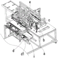
图1是本发明的包装设备的第一视角立体图,图中隐去了机架的部分结构;Fig. 1 is the perspective view of the first viewing angle of the packaging equipment of the present invention, in which part of the structure of the frame is hidden;
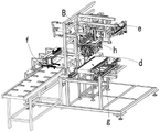
图2是本发明的包装设备的第二视角立体图,图中隐去了机架的部分结构;Fig. 2 is a second perspective perspective view of the packaging equipment of the present invention, in which part of the structure of the frame is hidden;
图3是本发明的开袋机构及PE袋供应机构的局部仰视图(图中隐去了给料机);Fig. 3 is a partial bottom view of the bag opening mechanism and the PE bag supply mechanism of the present invention (the feeder is hidden in the figure);
图4是本发明的开袋机构及PE袋供应机构的立体图;Fig. 4 is the perspective view of bag opening mechanism and PE bag supply mechanism of the present invention;
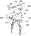
图5是本发明的翻袋机构的立体图;Fig. 5 is a perspective view of the bag turning mechanism of the present invention;
图6是本发明的翻袋机构的主视图;Fig. 6 is the front view of the bag turning mechanism of the present invention;
图7是图5中A区域的放大图;Figure 7 is an enlarged view of area A in Figure 5;
图8是本发明的翻袋机构的侧视图;Fig. 8 is a side view of the bag turning mechanism of the present invention;
图9是本发明的包装设备的主视图;Fig. 9 is the front view of packaging equipment of the present invention;
图10是本发明的袋口处理机构的立体图;Fig. 10 is a perspective view of the pocket processing mechanism of the present invention;
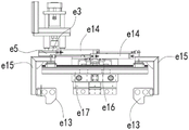
图11是本发明的袋口处理机构的侧视图;Fig. 11 is a side view of the pocket processing mechanism of the present invention;
图12是图2中B区域的放大图;Figure 12 is an enlarged view of area B in Figure 2;
图13是本发明的袋口塑封机构的第一视角的立体图(图中隐去了框架的部分结构);Fig. 13 is a perspective view of the first angle of view of the bag opening plastic sealing mechanism of the present invention (partial structure of the frame is hidden in the figure);
图14是本发明的袋口塑封机构的第二视角的立体图(图中隐去了框架的部分结构);Fig. 14 is a perspective view of a second angle of view of the bag opening plastic sealing mechanism of the present invention (partial structure of the frame is hidden in the figure);
图15是本发明的袋口塑封机构具有袋口夹持组件和抽真空组件的第一视角的立体图;Fig. 15 is a perspective view of the bag opening plastic sealing mechanism of the present invention with a first viewing angle of the bag opening clamping assembly and the vacuum pumping assembly;
图16是本发明的袋口塑封机构具有袋口夹持组件和抽真空组件的第二视角的立体图。Fig. 16 is a perspective view of the bag opening plastic sealing mechanism with a bag opening clamping assembly and a vacuuming assembly from a second perspective of the present invention.
具体实施方式detailed description
本发明的目的、优点和特点,将通过下面优选实施例的非限制性说明进行图示和解释。这些实施例仅是应用本发明技术方案的典型范例,凡采取等同替换或者等效变换而形成的技术方案,均落在本发明要求保护的范围之内。Objects, advantages and features of the present invention will be illustrated and explained by the following non-limiting description of preferred embodiments. These embodiments are only typical examples of applying the technical solutions of the present invention, and all technical solutions formed by adopting equivalent replacements or equivalent transformations fall within the protection scope of the present invention.
在方案的描述中,需要说明的是,术语“中心”、“上”、“下”、“左”、“右”、“前”、“后”、“竖直”、“水平”、“内”、“外”等指示的方位或位置关系为基于附图所示的方位或位置关系,仅是为了便于描述和简化描述,而不是指示或暗示所指的装置或元件必须具有特定的方位、以特定的方位构造和操作,因此不能理解为对本发明的限制。此外,术语“第一”、“第二”、“第三”仅用于描述目的,而不能理解为指示或暗示相对重要性。并且,在方案的描述中,以操作人员为参照,靠近操作者的方向为近端,远离操作者的方向为远端。In the description of the scheme, it should be noted that the terms "center", "upper", "lower", "left", "right", "front", "rear", "vertical", "horizontal", " The orientation or positional relationship indicated by "inner", "outer", etc. is based on the orientation or positional relationship shown in the drawings, and is only for the convenience of description and simplification of description, rather than indicating or implying that the device or element referred to must have a specific orientation , constructed and operated in a particular orientation and therefore should not be construed as limiting the invention. In addition, the terms "first", "second", and "third" are used for descriptive purposes only, and should not be construed as indicating or implying relative importance. Moreover, in the description of the solution, with the operator as a reference, the direction close to the operator is the proximal end, and the direction away from the operator is the distal end.
下面结合附图对本发明揭示的包装设备进行阐述,如附图1、附图2所示,其包括机架a,所述机架a上设置:The packaging equipment disclosed by the present invention is set forth below in conjunction with the accompanying drawings, as shown in accompanying drawing 1 and accompanying drawing 2, it comprises frame a, is set on described frame a:
开袋机构b,其用于将平铺在平板上的PE袋打开;Bag opening mechanism b, which is used to open the PE bag laid flat on the flat plate;
翻袋机构c,其用于将所述开袋机构b打开的PE袋由袋口朝向侧方的状态转动至袋口朝上的状态;Bag turning mechanism c, which is used to turn the PE bag opened by the bag opening mechanism b from the state where the mouth of the bag is facing sideways to the state where the mouth of the bag is facing upward;
第一输送机d,其设置于所述翻袋机构c旁,其在第一高度和第二高度之间移动,在第一高度处,其输送面不高于所述翻袋机构c;在第二高度处,其输送面与袋口朝上的PE袋的底部贴合或贴近;The first conveyor d, which is arranged beside the bag turning mechanism c, moves between the first height and the second height, and at the first height, its conveying surface is not higher than the bag turning mechanism c; At the second height, its conveying surface fits or is close to the bottom of the PE bag with the mouth facing up;
袋口处理机构e,其设置在所述第一输送机d上方,用于使所述第一A pocket processing mechanism e, which is arranged above the first conveyor d, is used to make the first
输送机d上的PE袋的袋口保持打开状态。The mouth of the PE bag on the conveyor d remains open.
如附图1所示,所述开袋机构b设置在所述机架a的底架的右侧,如附图3、附图4所示,所述开袋机构包括用于铺放PE袋的平板1及位于平板1上、下两侧的上吸附组件3和下吸附组件2,所述平板1上开设有供下吸附组件2的下吸盘2a穿过的穿孔。As shown in the accompanying drawing 1, the bag opening mechanism b is arranged on the right side of the underframe of the frame a, as shown in the accompanying drawings 3 and 4, the bag opening mechanism includes a The
如附图1所示,所述平板1水平设置在所述底架的矩形框上,如附图3所示,所述下吸附组件2的下吸盘2a为四个且呈矩形分布在第一连接架2b上,所述第一连接架2b设置在第一气缸2c上,所述第一气缸2c通过固定架2d连接在所述平板1的底部,所述第一气缸驱动所述下吸盘2a沿垂直于所述平板1的方向移动,如附图4所示,所述平板1上开设有与每个所述下吸盘2a匹配的穿孔1a。当然,所述第一气缸2c不是必须的,所述下吸盘2a可以直接设置在所述平板1的底部。As shown in the accompanying drawing 1, the
如附图1所示,所述上吸附组件3设置在所述底架上方的上立架上且位于所述平板1上方,如附图4所示,其包括第二气缸3a,所述第二气缸3a连接吸盘架3b,所述吸盘架3b上设置有四个上吸盘3c,所述上吸盘3c与所述下吸盘2a位置一一对应。当需要开袋时,所述第二气缸3a的气缸轴伸出使所述上吸盘3c与平板1上的PE袋的顶面抵接,所述上吸盘3c吸附PE袋的顶面,所述下吸盘2a吸附PE袋的底面,然后,所述第二气缸3a的气缸轴缩回,从而上吸盘3c与下吸盘2a配合将PE袋打开,此时,PE袋的袋口朝向所述第一输送机,因此需要将PE袋翻转至开口朝上的状态才能方便地进行装料。As shown in Figure 1, the upper adsorption assembly 3 is arranged on the upper stand above the underframe and above the
在开袋之前,需要先把未打开的PE袋以平铺的状态放置于所述平板1上且位于所述上、下吸附组件之间,此时,上吸盘3c和下吸盘2a吸附所述PE袋上靠近开口的区域。Before opening the bag, it is necessary to place the unopened PE bag on the
在一种实施例中,可以由人工逐一将PE袋放置到上述位置,当然也可以通过自动化设备来实现。In one embodiment, the PE bags can be placed in the above positions one by one manually, and of course it can also be realized by automatic equipment.
本实施例中,如附图2所示,通过设置PE袋供应机构f来实现PE袋的供应,所述PE袋供应机构f设置于开袋机构旁,具体是位于所述开袋机构的右侧。In this embodiment, as shown in accompanying drawing 2, the supply of PE bag is realized by setting PE bag supply mechanism f, and described PE bag supply mechanism f is arranged on the side of bag opening mechanism, specifically is positioned at the right side of described bag opening mechanism. side.
如附图3、附图4所示,所述PE袋供应机构f包括移载机10、给料机30、第一推动机构50及第二推动机构70。As shown in accompanying drawings 3 and 4 , the PE bag supply mechanism f includes a
如附图4所示,所述移载机10包括一组轴线沿纵向延伸的真空吸头11,所述真空吸头11设置在一升降架12上,所述升降架12连接驱动其升降的升降气缸13,所述升降气缸13设置在一平移驱动装置14上,所述平移驱动装置14固定在机架a上,所述平移驱动装置14可以是滑台气缸、直线伺服模组等,其驱动所述升降气缸13沿平行于所述第一输送机的输送方向在第一位置及第二位置间移动,在第一位置处,所述真空吸头11可由所述给料机30处吸附PE袋;在第二位置处,所述真空吸头11可使其吸附的PE袋移动到所述平板1上且处于第一推动机构50的第一推杆的移动路径上。As shown in Figure 4, the
如附图4所示,所述给料机30可以是一个皮带输送机,其输送带上设置有与未打开的PE袋匹配的PE袋限制槽31,所述PE袋限制槽31是所述皮带输送机的输送带上设置的一组呈矩形分布的挡块32围合而成,未打开的PE袋以平铺的状态限位在所述限制槽PE袋限制槽31处并向所述移载机10进行输送。当然,在其他实施例中,所述给料机30也可以和现有技术一样,使PE袋以平铺的状态堆叠在一料槽中,所述料槽连接驱动其升降的抬升机构,所述给料机30位于第一位置的一组真空吸头11的正下方,当所述移载机10从堆叠的PE袋上方移走一个或多个时,所述抬升机构使所述料槽抬升一定高度,从而使所述移载机10能够继续吸取所述料槽中的PE袋。As shown in accompanying drawing 4, described
如附图3、附图4所示,所述第一推动机构50包括一组第一推杆51,所述第一推杆51所述平板1垂直,当然,所述第一推杆51也可以是位于所述平板上方的推块等,所述第一推杆51连接驱动其平移的第一推送驱动机构52,所述第一推杆51的移动方向平行于所述升降气缸13的平移方向,所述第一推送驱动机构52可以是气缸或直线伺服模组等,所述第一推送驱动机构可以设置在所述平板1的底部,也可以设置在所述平板1的上方,当所述第一推送驱动机构设置在所述平板1的底部时,所述平板1上开设有供所述第一推杆51移动的第一长条孔53,所述第一长条孔53的延伸方向与所述第一输送机的输送方向平行,所述第一推动机构50将位于所述第一推杆51左侧的PE袋推送到所述第二推动机构70的第二推杆的移动路径上。As shown in accompanying drawings 3 and 4, the first pushing
如附图3、附图4所示,所述第二推动机构70的结构与所述第一推动机构50的结构相同,其包括一组第二推杆71及驱动所述第二推杆71的第二推送驱动机构72,所述第二推杆71的移动方向与所述第一推杆51的移动方向垂直所述第二推杆71将由第一推动机构50推送到其工作区域处的所述PE袋推送到所述上吸附组件3和下吸附组件2之间进行开袋。所述第二推送驱动机构72可以是气缸或直线伺服模组等,当所述第二推送驱动机构设置在所述平板1的底部时,所述平板1上开设有供所述第二推杆71移动的第二长条孔75,所述第二长条孔75的延伸方向与所述第一长条孔的延伸方向垂直。As shown in accompanying drawing 3, accompanying drawing 4, the structure of described second pushing
如附图4所示,所述平板1上还设置有两个防止所述PE袋在被第一推动机构50驱动过程中出现位置偏移的导引挡边54,所述平板1上还设置有用于限制所述PE袋移动到位置的限位挡边73,所述限位挡边73与所述导引挡边54的延伸方向垂直,靠近所述开袋机构b的导引挡边54的端部设置有导引块74,所述导引块74与所述限位挡边73之间的间距与所述PE袋的宽度相当。As shown in Figure 4, two
供应PE袋时,所述给料机30将PE袋逐一输送到其输出端并停止,所述移载机10驱动其上的真空吸头11将所述给料机30末端的PE袋吸附,随后移动到所述第一推杆51的前方,所述第一推送驱动机构52驱动所述第一推杆51向所述第二推动机构70方向移动并将所述PE袋推送到所述第二推杆71的前方,所述第二推送驱动机构72驱动所述第二推杆71向所述开袋机构b方向移动至PE袋被阻挡器90挡住,此时,PE袋覆盖全部所述穿孔,所述上吸附组件和下吸附组件可以进行吸附开袋。When supplying PE bags, the
如附图1所示,所述翻袋机构c设置在所述上吸附组件3旁,所述翻袋机构c包括设置在所述上吸附组件左侧的轴座200,如附图5所示,所述轴座200的左侧可自转地设置有水平轴400、设置在所述水平轴400侧部的PE袋抓取夹爪600及驱动所述水平轴400自转的轴驱动组件800,所述翻袋机构c是通过PE袋抓取夹爪600抓取打开的PE袋,然后通过所述轴驱动组件800驱动所述水平轴400自转90°,从而使开口朝向侧方的PE袋转动至开口朝上。As shown in Figure 1, the bag turning mechanism c is arranged beside the upper adsorption assembly 3, and the bag turning mechanism c includes a
如附图5所示,所述轴座200包括固定在机架的上立架侧部的立板201,所述立板201朝向所述第一输送机的一侧设置有两个带座轴承202,所述水平轴400可自转地设置在两个带座轴承202上。As shown in the accompanying drawing 5, the
如附图6所示,所述PE袋抓取夹爪600包括两个枢接在所述水平轴400侧部的安装臂601,两个所述安装臂601转动时所绕的轴602与所述水平轴400垂直,每个所述安装臂601的远端连接一支撑板603,所述支撑板位于所述安装臂朝向所述上吸附组件3的侧部,两个所述安装臂601还分别连接一开闭气缸604,所述开闭气缸604驱动两个所述安装臂601同步反向转动。当然所述开闭气缸604也可以是伺服直线模组、液压缸等可行装置,两个所述开闭气缸位于两个所述安装臂601之间,且它们的一端铰接在水平轴400的侧部,它们的另一端分别铰接在一所述安装臂601的内侧(两个安装臂相对的一侧)。在所述两个支撑板603伸入到所述PE袋中时,两个所述开闭气缸的气缸轴伸出,两个所述支撑板603打开可以与PE袋的两个短侧膜抵接并使PE袋的袋口保持打开状态;当两个所述开闭气缸的气缸轴缩回时,两个所述支撑板603闭合,这时可以方便地将两个支撑板603伸入到PE袋内以及从PE袋内取出。当然,两个所述开闭气缸也可以设置在两个安装臂的外侧。As shown in FIG. 6 , the PE
如附图6所示,为了避免在转动过程中,所述PE袋从两个所述支撑板603上脱落,所述安装臂601的外侧还设置有夹持组件605,所述夹持组件605与所述支撑板603配合进行PE袋的夹持。As shown in Figure 6, in order to prevent the PE bag from falling off from the two
如附图6所示,所述夹持组件605包括枢接在所述安装臂601上的转动臂606,所述转动臂606连接夹紧杆608及夹持气缸607,所述转动臂606近似为L形,其上端连接一夹持气缸607,其中部连接在所述安装臂601外侧的铰接座上,其下端连接所述夹紧杆608。所述夹持气缸607的上端铰接在所述安装臂601的外侧面,其下端与所述转动臂606的上端枢接,所述夹持气缸607驱动所述转动臂606转动以使所述夹紧杆608由于所述支撑板603保持间距的位置移动至与支撑板603的外侧面紧贴;当两个所述夹持气缸607的气缸轴缩回时,所述夹紧杆608与支撑板603保持间距,此时,PE袋的两个较短的侧壁可以进入到所述夹紧杆608和支撑板之间;所述夹紧杆608与所述支撑板603贴合并将位于它们之间的PE袋夹持;当两个所述夹持气缸607的气缸轴伸出时,所述夹紧杆608与所述支撑板603贴合并将位于它们之间的PE袋夹持。当然,所述夹持气缸607也可以是液压缸或电动推杆等。As shown in Figure 6, the clamping
如附图7所示,为了保证夹持的稳定性,所述支撑板603的外侧面形成有弧形凹槽609,所述弧形凹槽609的延伸方向与所述安装臂601转动时所绕的轴平行,所述夹紧杆608上套装有圆管610,所述圆管610可以采用橡胶管、硅胶管等,所述圆管610可嵌入到所述弧形凹槽609内,这样在夹持时,夹紧杆608可以使PE袋的局部嵌入到所述弧形凹槽609内,从而保证塑料不会从所述夹紧杆608和支撑板603之间脱落,同时可以对PE袋进行保护,避免其出现明显的压痕。As shown in Figure 7, in order to ensure the stability of the clamping, an arc-shaped
如附图5、附图8所示,所述轴驱动组件800包括L形摆动臂802,所述L形摆动臂802的第一端固定连接所述水平轴400的一端,其第二端位于所述水平轴400的外侧且与所述第一驱动气缸801的气缸轴铰接,所述第一驱动气缸801倾斜设置在所述水平轴400的上方,其与所述L形摆动臂802连接的一端较低,并且所述第一驱动气缸801通过第一杆端关节轴承808连接所述L形摆动臂802。所述第一驱动气缸801的另一端枢接在转架803的中间位置,所述转架803包括主杆809及垂直连接在主杆809同一侧的下杆810和上杆811,所述第一驱动气缸801与主杆809的连接点位于所述下杆810和上杆811之间,所述转架803的下杆810连接平行于所述水平轴400的二级转轴804,所述二级转轴804设在固定座813。所述上杆811连接驱动所述转架803绕所述二级转轴804自转的第二驱动气缸805,所述第二驱动气缸805的一端通过第二杆端关节轴承812连接所述转架803的上杆,所述第二驱动气缸805的另一端铰接在位置固定的安装件814上,所述安装件814固定在机架a上。As shown in accompanying drawing 5, accompanying drawing 8, described
当然,所述第一驱动气缸801和第二驱动气缸也可以用伺服直线模组、液压缸等来代替。Of course, the
实际使用时,所述轴驱动组件800驱动所述PE袋抓取夹爪600在位置一、位置二、位置三、位置四之间移动。In actual use, the
当所述第一驱动气缸801的气缸轴伸出,所述第二驱动气缸的气缸轴缩回时,所述PE袋抓取夹爪600位于位置一处,此时,所述PE袋抓取夹爪600处于所述水平轴400的下方且保持竖直状态,且所述PE袋抓取夹爪600的支撑板603可以伸入到开袋机构处打开的PE袋内。When the cylinder shaft of the
当所述第一驱动气缸801的气缸轴缩回,所述第二驱动气缸的气缸轴缩回时,所述PE袋抓取夹爪600位于位置二处,此时,所述PE袋抓取夹爪600相对位置一处的PE袋抓取夹爪600转动90度并保持水平状态,此时,PE袋抓取夹爪可将其抓取的PE袋转动至开口朝上且间隙位于第一输送机d的上方。When the cylinder shaft of the
当所述第一驱动气缸801的气缸轴伸出,所述第二驱动气缸的气缸轴伸出时,所述PE袋抓取夹爪600位于位置三处,所述位置三位于位置一和位置二之间且靠近位置一,此时,所述PE袋抓取夹爪600的支撑板603位于打开的PE袋的开口前方等待进行PE袋的抓取。When the cylinder shaft of the
当所述第一驱动气缸801的气缸轴缩回,所述第二驱动气缸的气缸轴伸出时,所述PE袋抓取夹爪600位于位置四处,所述位置四位于所述位置二的上方,此时,所述PE袋抓取夹爪600的支撑板603以从开口朝上的PE袋中移出。移出后,所述PE袋被所述第一输送机d承接。When the cylinder shaft of the
如附图9所示,所述第一输送机d可以是已知的皮带输送机或滚筒输送机,优选为皮带输送机,所述皮带输送机连接驱动其在第一高度和第二高度之间移动的顶升机构i,所述顶升机构i包括固定在一托板i1上的直线驱动装置i2,所述直线驱动装置i2可以是气缸、电动推杆或液压缸等,所述直线驱动装置i2连接所述第一输送机d的底部,所述第一输送机d的底部还连接导向轴i3,所述导向轴i3滑动地插接在所述托板i1上设置的轴套i4中,所述托板i1固定在所述机架a上。通过所述第一输送机d的升降能够有效避免对所述PE袋抓取夹爪600的转动的干涉。As shown in Figure 9, the first conveyor d can be a known belt conveyor or roller conveyor, preferably a belt conveyor, and the belt conveyor is connected to drive it between the first height and the second height. The jacking mechanism i that moves between, the jacking mechanism i includes a linear drive device i2 fixed on a pallet i1, the linear drive device i2 can be an air cylinder, an electric push rod or a hydraulic cylinder, etc., the linear drive The device i2 is connected to the bottom of the first conveyor d, and the bottom of the first conveyor d is also connected to the guide shaft i3, and the guide shaft i3 is slidably inserted into the sleeve i4 provided on the pallet i1 , the pallet i1 is fixed on the frame a. The lifting and lowering of the first conveyor d can effectively avoid interference with the rotation of the PE
当开口朝上的所述PE袋位于所述第一输送机d上后,即可进行装料,装料的具体操作可以和现有技术一样,采用装料机器人来实现,其具体结构为已知技术,此处不作赘述。When the PE bag with the opening facing upwards is located on the first conveyor d, it can be loaded. The specific operation of loading can be the same as the prior art, using a loading robot. The specific structure is as follows: Known technology, not repeat them here.
在进行装袋时,所述第一输送机d上的PE袋的袋口容易在重力或外部碰撞等外力作用下出现不能保持打开状态的情况,这会严重影响装袋作业的有效实现。因此通过所述袋口处理机构e以使所述袋口保持张开状态。During bagging, the bag mouth of the PE bag on the first conveyor d is likely to fail to keep open under the action of external force such as gravity or external collision, which will seriously affect the effective realization of the bagging operation. Therefore, the pocket opening is kept open by the pocket handling mechanism e.
如附图1、附图10所示,所述袋口处理机构e包括吊设在机架a上的升降驱动组件e1,所述升降驱动组件e1包括至少固定在机架a上的升降驱动气缸e2,所述升降驱动气缸e2的气缸轴朝向并连接位于其下方的载板e3,所述升降驱动组件还包括连接所述载板e3的导向机构e4,所述载板e3设置在所述第一输送机d的输出端的外侧,所述载板e3上间隙设置有两根由所述第一输送机d的外侧延伸到所述第一输送机d上方的支杆e5,两根所述支杆e5对称分布在所述第一输送机d的输送面的两侧,所述支杆e5的延伸方向与所述第一输送机d的输送方向平行。所述支杆e5上延伸到所述第一输送机d上的部分设置推拉机构e6,所述推拉机构e6连接一扩张板e7并驱动所述扩张板e7往复直线平移,两个所述扩张板e7相对设置且它们的移动方向与第一输送机d的输送方向垂直,两个所述扩张板e7位于所述第一输送机d的输送面的正上方。As shown in accompanying drawing 1 and accompanying drawing 10, the bag opening processing mechanism e includes a lifting drive assembly e1 suspended on the frame a, and the lifting driving assembly e1 includes a lifting driving cylinder fixed at least on the frame a e2, the cylinder shaft of the lifting drive cylinder e2 faces and connects to the carrier plate e3 below it, the lifting drive assembly also includes a guide mechanism e4 connected to the carrier plate e3, and the carrier plate e3 is arranged on the second On the outside of the output end of a conveyor d, two struts e5 extending from the outside of the first conveyor d to the top of the first conveyor d are provided in the gap on the carrier plate e3, and the two struts e5 are symmetrically distributed on both sides of the conveying surface of the first conveyor d, and the extension direction of the struts e5 is parallel to the conveying direction of the first conveyor d. The part of the pole e5 extending to the first conveyor d is provided with a push-pull mechanism e6. The push-pull mechanism e6 is connected to an expansion plate e7 and drives the expansion plate e7 to reciprocate and linearly translate. The two expansion plates e7 are arranged oppositely and their moving direction is perpendicular to the conveying direction of the first conveyor d, and the two expansion plates e7 are located directly above the conveying surface of the first conveyor d.
如附图10所示,所述推拉机构e6包括推拉气缸e8,所述推拉气缸e8设置在所述支杆e5底部的竖板e9上,所述推拉气缸e8的气缸轴通过转接架e10连接所述扩张板e7,所述转接架e10连接水平导杆,所述水平导杆滑动设置在所述竖板e9上设置的导套中,所述推拉气缸e8的气缸轴伸出时,所述扩张板e7靠近所述第一输送机d的宽度中心线d1(所述宽度中心线d1到所述第一输送机d的输送带的两侧的距离相同),这样能够有效地保证所述扩张板e7伸入到所述PE袋中。同时,两个所述扩张板e7为一折弯板,并且两个所述扩张板e7的上折弯部e11构成上端宽、下端窄的八字口,这样可以对放料动作进行导向,两个所述推拉气缸的气缸轴伸出时,两个所述扩张板移动到或接近所述宽度中心线d1,从而两个所述扩张板贴合或贴近。As shown in Figure 10, the push-pull mechanism e6 includes a push-pull cylinder e8, the push-pull cylinder e8 is arranged on the vertical plate e9 at the bottom of the pole e5, and the cylinder shaft of the push-pull cylinder e8 is connected through an adapter frame e10 The expansion plate e7 and the adapter frame e10 are connected to a horizontal guide rod, and the horizontal guide rod is slidably arranged in the guide sleeve provided on the vertical plate e9. When the cylinder shaft of the push-pull cylinder e8 is stretched out, the The expansion plate e7 is close to the width centerline d1 of the first conveyor d (the distance from the width centerline d1 to both sides of the conveyor belt of the first conveyor d is the same), which can effectively ensure that the Expansion plate e7 protrudes into said PE bag. At the same time, the two expansion plates e7 are a bent plate, and the upper bending parts e11 of the two expansion plates e7 form a splayed mouth with a wide upper end and a narrow lower end, so that the discharging action can be guided, and the two When the cylinder shaft of the push-pull cylinder is stretched out, the two expansion plates move to or approach the width center line d1, so that the two expansion plates are attached or close to each other.
如附图10、附图11所示,左侧的所述支杆e5上还设置有折叠机构e12,所述折叠机构e12用于使所述PE袋的两个短侧膜的靠近袋口的区域向内弯折呈V形。所述折叠机构e12包括两个压板e13,两个压板e13位于两个所述支杆e5之间的中间位置,所述压板e13到所述第一输送机的两侧的距离相同且其与所述扩张板e7的移动方向垂直,两个所述压板e13驱动它们同步移动的折叠驱动组件,所述折叠驱动组件包括两个笔形气缸e14,两个所述笔形气缸e14固定在所述竖板e9外侧面的第二连接架e17上且分别连接一滑动架e15,所述滑动架e15滑动设置在所述第二连接架e17上的导轨e16上,每个所述滑动架e15连接一所述压板e13,所述压板e13的底部低于所述扩张板e7的底部。两个所述笔形气缸e14的气缸轴伸出时,两个所述压板e13位于所述第一输送机d的两端外侧,此时不会对装料作为产生影响。所述转接架e10的底部设置有推送块,所述推送块与所述扩张板e7的竖直部之间保持间距,当所述推拉气缸e8的气缸轴伸出时,所述推送块e18位于所述第一输送机上的PE袋的外侧。As shown in accompanying drawing 10 and accompanying drawing 11, folding mechanism e12 is also provided on the said pole e5 on the left side, and described folding mechanism e12 is used for making the two short side films of described PE bag close to the bag opening The area bends inwards in a V shape. The folding mechanism e12 includes two pressing plates e13, and the two pressing plates e13 are located in the middle position between the two poles e5. The moving direction of the expansion plate e7 is vertical, and the two pressing plates e13 drive their synchronously moving folding drive assembly, which includes two pen-shaped air cylinders e14, and the two pen-shaped air cylinders e14 are fixed on the vertical plate e9 The second connecting frame e17 on the outer surface is connected to a sliding frame e15 respectively, and the sliding frame e15 is slidably arranged on the guide rail e16 on the second connecting frame e17, and each of the sliding frames e15 is connected to a pressing plate e13, the bottom of the pressing plate e13 is lower than the bottom of the expanding plate e7. When the cylinder shafts of the two pen-shaped cylinders e14 are stretched out, the two pressing plates e13 are located outside the two ends of the first conveyor d, which will not affect the charging operation at this time. The bottom of the adapter frame e10 is provided with a push block, and a distance is kept between the push block and the vertical part of the expansion plate e7. When the cylinder shaft of the push-pull cylinder e8 is stretched out, the push block e18 Located on the outside of the PE bag on the first conveyor.
在装袋完成后,两个所述笔形气缸e14的气缸轴缩回,此时,两个所述压板e13对所述PE袋的两个短侧膜的外侧接触后并推动两个侧壁膜的靠近开口的区域向内弯折呈V形,两个所述推拉气缸e8的气缸轴伸出使推送块推送所述PE袋的两个长侧膜的靠近顶部开口的区域向内弯折,从而所述PE袋靠近开口的区域被折弯呈M形袋口。After bagging is completed, the cylinder shafts of the two pen-shaped cylinders e14 are retracted. At this time, the two pressing plates e13 are in contact with the outsides of the two short side films of the PE bag and push the two side wall films. The area close to the opening is bent inward to form a V shape, and the cylinder shafts of the two push-pull cylinders e8 are stretched out so that the pushing block pushes the area near the top opening of the two long side films of the PE bag to bend inwardly, Therefore, the area near the opening of the PE bag is bent to form an M-shaped mouth.
所述包装设备还包括控制装置,所述控制装置可以根据预定的程序并结合设定位置设置的传感器来控制各机构工作进行自动包装,所述控制装置的控制原理为已知技术,此处不作赘述。The packaging equipment also includes a control device. The control device can control the work of each mechanism to perform automatic packaging according to a predetermined program and in combination with the sensors set at the set positions. The control principle of the control device is a known technology and will not be described here. repeat.
实施例2Example 2
在装料完成并对袋口进行处理后,需要对袋口进行封口。After the filling is completed and the bag mouth is processed, the bag mouth needs to be sealed.
因此,如附图2所示,本实施例在上述实施例1的基础上,在所述机架a上还设置有:Therefore, as shown in accompanying drawing 2, present embodiment is also provided with on the described frame a on the basis of above-mentioned embodiment 1:
第二输送机g,所述第二输送机g的输送面与处于第二高度的第一输送机d的输送面衔接;The second conveyor g, the conveying surface of the second conveyor g is connected with the conveying surface of the first conveyor d at the second height;
袋口塑封机构h,其设置在所述第二输送机g的上方设置且位于所述袋口处理机构e的下游,其用于将所述第二输送机g上的PE袋的袋口塑封。A bag mouth plastic sealing mechanism h, which is arranged above the second conveyor g and located downstream of the bag mouth processing mechanism e, and is used for plastic sealing the bag mouth of the PE bag on the second conveyor g .
所述第二输送机g同样可以是已知的滚筒输送机或皮带输送机,优选为皮带输送机。所述第二输送机g的输送方向与所述第一输送机d的输送方向相同,完成装袋及袋口处理的PE袋在所述第一输送机d的输送下输送到所述第二输送机g,所述第二输送机g将所述PE袋输送到所述袋口塑封机构h处进行封口。The second conveyor g can likewise be a known roller conveyor or a belt conveyor, preferably a belt conveyor. The conveying direction of the second conveyor g is the same as the conveying direction of the first conveyor d, and the PE bags that have completed bagging and bag opening processing are conveyed to the second conveyor d under the conveyance of the first conveyor d. Conveyor g, the second conveyor g transports the PE bag to the bag mouth plastic sealing mechanism h for sealing.
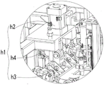
如附图12、附图13所示,所述袋口塑封机构h可以采用已知的塑封机来实现,所述袋口塑封机构h包括设置在机架a上的调高组件h1,所述调高组件h1的下方连接框架100并驱动框架100升降,所述框架100上设置有第一驱动组件300连接并驱动两个热熔组件实现闭第二输送机g上的PE袋的袋口塑封。As shown in accompanying drawing 12, accompanying drawing 13, described bag opening plastic sealing mechanism h can adopt known plastic sealing machine to realize, and described bag mouth plastic sealing mechanism h comprises height adjustment assembly h1 that is arranged on frame a, described The bottom of the height adjustment component h1 is connected to the
如附图12所示,所述调高组件h1包括设置在所述机架a的上立架上的调高气缸h2,所述调高气缸h2的气缸轴朝向且通过杆端关节轴承连接一滑动架h3,所述滑动架h3滑动设置在所述立架上设置的纵轨h4上,所述滑动架h3的底部连接所述框架100。As shown in Figure 12, the height adjustment assembly h1 includes a height adjustment cylinder h2 arranged on the upper stand of the frame a, the cylinder axis of the height adjustment cylinder h2 faces and is connected to a The sliding frame h3 is slidably arranged on the vertical rail h4 provided on the stand, and the bottom of the sliding frame h3 is connected to the
如附图13所示,所述框架100包括两根平行的主梁101以及垂直连接在两根主梁101之间的两根连梁102,两根所述主梁101的延伸方向与所述第二输送机g的输送方向平行且它们的两端分别通过端板103连接。As shown in Figure 13, the
所述第一驱动组件300可以是分别与一个热熔组件连接的直线移动机构,两个直线移动机构驱动两个所述热熔组件沿垂直于所述第二输送机g的输送方向平移实现开闭。The
如附图13所示,所述第一驱动组件300包括两根平行且可自转地设置于框架100的两个端板之间的主轴301,两根所述主轴301通过轴承可自转且等高地安装在两个所述端板103的中间位置,两根所述主轴301之间的间距可以根据需要进行设置,此处不作赘述,它们位于两个所述主梁101的下方。每根所述主轴301连接一位于其下方的热熔组件500,所述主轴301连接驱动其转动的自转驱动组件300,所述自转驱动组件驱动两个所述主轴同步反向转动时带动两个所述热熔组件500同步摆动实现开闭。As shown in FIG. 13 , the
在一种实施例中,所述主轴可以由电机、齿轮减速机构构成的自转驱动组件驱动进行自转。In one embodiment, the main shaft can be driven to rotate by an autorotation drive assembly composed of a motor and a gear reduction mechanism.
本实施例中,如附图13所示,所述自转驱动组件包括上位气缸302,所述上位气缸302通过第一联动组件303连接两根所述主轴并驱动两根所述主轴自转。In this embodiment, as shown in FIG. 13 , the autorotation driving assembly includes an
如附图13、附图14所示,所述上位气缸302的数量可以仅有一个,优选所述上位气缸302为两个,它们倾斜且可自转地设置在一所述主梁101的顶部,两个上位气缸302的气缸轴朝下且头部位于两根主梁101之间,每个上位气缸302的缸体可自转地设置在主梁101上的铰接座304上,且连接缸体和铰接座304的旋转轴与所述主轴301平行。每个上位气缸302的气缸轴连接一第一联动组件303,两个所述第一联动组件303连接在两根主轴301的两端,这样能够有效保证驱动的稳定性和可靠性 。As shown in accompanying
如附图13、附图14所示,所述第一联动组件303包括第一摆臂305,所述第一摆臂305大致为L形,当然也可以是其他可行的形状,如T形等,所述第一摆臂305内侧的上端308枢接所述上位气缸302的气缸轴,更优的,所述上位气缸302的气缸轴通过第三杆端关节轴承309与所述第一摆臂305枢接;所述第一摆臂305的中部连接一所述主轴301,具体是套装并卡接在所述主轴301上;所述第一摆臂305内侧的下端310与联动臂306的一端枢接,所述联动臂306靠近所述上位气缸302的一端高于其相对的另一端,所述联动臂306的另一端与第二摆臂307的内端枢接,所述第二摆臂307连接另一所述主轴301,具体是套装并卡接在另一所述主轴301上。连接所述联动臂306与第二摆臂307的第三连接轴311位于连接所述第一摆臂305与上位气缸302的第一连接轴312及连接所述第一摆臂305与联动臂306的第二连接轴313之间。As shown in accompanying
当所述上位气缸的气缸轴伸出、缩回时,所述第一摆臂305带动与其连接的转轴自转,所述主轴301带动所述联动臂306进而带动所述第二摆臂307使另一所述主轴301自转,两根所述主轴301同步反向转动从而使连接在它们上的两个热熔组件500开闭。When the cylinder shaft of the upper cylinder is extended and retracted, the
如附图14所示,每个所述主轴301可以通过两根靠近其两端的摆动臂连接位于其下方的热熔组件500,每个所述摆动臂314的下端可转动地连接有一T形件315,两个第一联动组件的两个所述T形件315之间连接所述热熔组件500,所述T形件315还与一微调臂316的下端枢接,所述微调臂316的上端枢接所述框架100上的连接座317,所述微调臂316的延伸方向与所述摆动臂314的延伸方向平行且位于所述摆动臂314的外侧。当所述主轴301带动所述摆动臂314转动时,所述T形件315跟随所述摆动臂314转动的同时,所述微调臂316可以驱动所述T形件315相对所述摆动臂314转动,从而使两个热熔组件500闭合状态时,它们的两个热熔头的相对面平行且为竖直状态,这样能够保证热熔头与塑封袋充分接触及避免塑封袋弯折变形,从而实现有效地塑封。As shown in Figure 14, each of the
如附图14所示,所述微调臂316的两端通过两个第四杆端关节轴承318连接所述T形件315和连接座317,这样可以使微调臂316具有更大的移动自有度,从而使热熔头能够与PE袋更好的贴合。As shown in accompanying drawing 14, the two ends of described fine-
在两个热熔组件闭合前,需要先将PE袋的袋口闭合以使所述热熔组件稳定的实现热塑封。因此,如附图15所示,所述框架上还设置有袋口夹持组件700,所述袋口夹持组件700包括设置在所述框架100上的第二驱动组件702,所述第二驱动组件702连接并驱动两个夹持件701实现第二输送机g上的PE袋的袋口的闭合。所述第二驱动组件可以采用两个气缸驱动两个所述夹持件沿垂直于所述第二输送机g的输送方向平移实现开闭。Before the two hot-melt components are closed, the mouth of the PE bag needs to be closed first so that the hot-melt components can be stably heat-molded. Therefore, as shown in FIG. 15 , the frame is also provided with a
如附图15、附图16所示,所述第二驱动组件702包括下位气缸703及第二联动组件704,所述下位气缸703设置在所述框架100上且连接第二联动组件704,所述第二联动组件704连接两个所述主轴301及两个所述夹持件701,所述第二联动组件704在所述下位气缸703的驱动下带动两个所述夹持件701开闭。所述上位气缸和下位气缸也可以是电动推杆、直线电机、液压缸等。As shown in Figure 15 and Figure 16, the
如附图15、附图16所示,每个所述夹持件701为一长方体块体,并且每个所述夹持件701上开设有供所述热熔组件500穿过的避让孔705,当然,所述夹持件701也可以整体位于所述热熔组件500的下方或上方。同时,两个所述夹持件701朝向所述第一输送机d的一端分别设置有导引板706,两个导引板706呈八字型分布或楔形分布,且两个导引板706远离所述夹持件701的远端的距离大于它们近端的距离,从而便于使PE袋能够顺利进入到两个所述夹持件701之间。As shown in Figure 15 and Figure 16, each of the clamping
如附图16所示,所述下位气缸703的数量可以仅有一个,优选为两个气缸,两个下位气缸703倾斜设置,其较高的一端枢接所述主梁101侧部的安装座707上,且下位气缸703与所述安装座707连接的轴平行于所述主轴301,所述下位气缸703的较低的一端枢接一第二联动组件704,两个所述第二联动组件704连接在两根主轴301的两端且位于两个端板的外侧,这样能够有效保证驱动的稳定性。As shown in Figure 16, the number of the
如附图16所示,所述第二联动组件704包括第一摆动臂708、第二摆动臂709及中间摆动臂710,所述第一摆动臂708通过轴承可自转地设置在一所述主轴301的端部且其下端连接一夹持件701,所述第二摆动臂709通过轴承可自转地设置在另一所述主轴301的端部且其下端连接另一夹持件701,所述第一摆动臂708和第二摆动臂709通过它们之间的中间摆动臂710连接,所述中间摆动臂710枢接在所述第一摆动臂708内侧的第一连接部721和第二摆动臂709内侧的第二连接部722,其所述中间摆动臂710与所述第一连接部721的连接点高于所述中间摆动臂与所述第二连接部722的连接点,所述第一摆动臂708或第二摆动臂709的内侧中部的连接块719与所述下位气缸703枢接,较优的,所述下位气缸703通过第五杆端关节轴承711连接所述第一摆动臂708,所述下位气缸703驱动所述第一摆动臂708和第二摆动臂709同步绕各自连接的主轴301转动且所述第一摆动臂708或第二摆动臂709的转动方向相反。As shown in Figure 16, the
如附图16所示,所述第一摆动臂708下端可自转地连接第一转动件712,所述第一转动件712近似为L形,所述第一转动件712的中部连接在所述第一摆动臂708下端,所述第一转动件712的下端连接一位于其内侧的夹持件701,所述第一转动件712的上端连接一位于其外侧的第一调节杆713,所述第一调节杆713的延伸方向与所述第一摆动臂708的第一主干714的长度方向平行,且其上端枢接在所述框架100上,具体是枢接在框架的端板外侧。As shown in Figure 16, the lower end of the
如附图16所示,所述第二摆动臂709的下端可自转地连接第二转动件716,所述第二转动件716连接另一位于其内侧的夹持件701及一位于其外侧的第二调节杆717,所述第二调节杆717的延伸方向与所述第二摆动臂709的第二主干718的长度方向平行,且其上端枢接在所述框架100上,具体是枢接在框架的端板外侧。As shown in Figure 16, the lower end of the
如附图16所示,所述第一调节杆713的两端通过第六杆端关节轴承723连接所述端板及第一摆动臂708,所述第二调节杆717的两端分别通过第七杆端关节轴承724连接所述端板及第二转动件716。As shown in Figure 16, both ends of the
如附图16所示,在封口前,常需要对PE袋进行抽真空,对应的,所述框架100上还是设置有抽真空组件900,所述抽真空组件900包括抽真空吸管901及驱动所述抽真空吸管901上下移动的吸头驱动装置902,所述抽真空吸管901位于两个处于打开状态的夹持件之间且可移动所述热熔组件的下方,所述抽真空吸管901具有扁平段903以及位于所述扁平段903上方的圆管段904,所述圆管段904通过一转接块905连接所述吸头驱动装置902,所述吸头驱动装置902设置在所述主梁101顶部的顶板104上,所述吸头驱动装置902是能够产生直线移动的装置,例如是气缸、液压缸、直线电机等,较优的,所述吸头驱动装置902为气缸,其垂直设置在所述顶板104上方的立架906上,所述转接块905滑动设置在所述立架906上设置的导向轨907上。As shown in Figure 16, before sealing, it is often necessary to vacuumize the PE bag. Correspondingly, the
如附图16所示,为了保证所述抽真空组件900的抽真空吸管901抽真空吸管901能够有效地伸入到PE袋中,每个所述夹持件701上还设置有位于所述热熔组件500上方的真空吸盘715,当所述开袋驱动机构702驱动两个所述夹持件701闭合时,两个所述夹持件701上的真空吸盘715与PE袋的相对的两侧外壁贴合,所述真空吸盘715与PE袋的贴合位置靠近PE袋的袋口。此时,两组真空吸盘715抽真空,接着,所述开袋驱动机构702驱动两个所述夹持件701打开,从而真空吸盘715可以带动PE袋的袋口打开到一定程度,打开后,所述抽真空组件900的抽真空吸管901抽真空吸管901可以伸入到所述PE袋内,抽真空吸管901抽真空吸管901伸入后,所述开袋驱动机构702再次驱动两个所述夹持件701关闭,此时,PE袋的袋口关闭,接着可以通过抽真空吸管901抽真空吸管901将PE袋内抽真空,抽真空后将所述抽真空吸管901抽真空吸管901从PE袋内抽出,然后,所述第一驱动组件300驱动两个所述热熔组件500闭合进行塑封。As shown in Figure 16, in order to ensure that the vacuum suction pipe 901 of the
实施例3Example 3
本实施例揭示了一种包装方法,其特征在于:至少包括如下步骤:This embodiment discloses a packaging method, which is characterized in that it includes at least the following steps:
S1,提供如上实施例的包装设备;S1, providing the packaging equipment of the above embodiment;
S2,将一平铺的PE袋置于开袋机构b处,在确定开袋机构b处有一PE袋时,所述开袋机构b的上吸附组件3的上吸盘3c下移并吸附在平板1上的一PE袋的顶面,下吸盘2a将PE袋的底面吸附,接着所述第二气缸3a驱动所述上吸盘3c上移从而将所述PE袋打开。PE袋置于开袋机构处可由上述的PE袋供应机构来实现。S2, place a flat PE bag at the bag opening mechanism b, and when it is determined that there is a PE bag at the bag opening mechanism b, the upper suction cup 3c of the upper adsorption component 3 of the bag opening mechanism b moves down and is adsorbed on the
S3,翻袋机构c启动抓取打开的PE袋并在所述第一输送机d处于第一高度时,使PE袋转动90°呈袋口朝上的状态。S3, the bag turning mechanism c starts to grab the opened PE bag, and when the first conveyor d is at the first height, rotates the PE bag by 90° so that the mouth of the bag faces upward.
具体的,在所述开袋机构b开袋时,所述PE袋抓取夹爪600由保持在位置三处且两个开闭气缸的气缸轴缩回使两个支撑板保持闭合状态。所述PE袋打开后,轴驱动组件800驱动水平轴400自转使所述PE袋抓取夹爪600转动到位置一处,所述支撑板移动到所述PE袋内,接着,所述开闭气缸的气缸轴伸出,所述支撑板支撑在PE袋的两个短侧膜的内侧,同时所述夹持组件的夹持气缸的气缸轴伸出使夹持杆与支撑板夹持所述PE袋的两个短侧膜。接着,所述轴驱动组件800驱动所述水平轴400自转90°从而使第一位置的PE袋抓取夹爪600转动至第二位置,此时,被所述PE袋抓取夹爪抓取的所述PE袋转动90°至开口朝上的状态。Specifically, when the bag opening mechanism b opens the bag, the PE
S4,所述第一输送机d移动到第二高度,所述翻袋机构c松开所述PE袋使PE袋置于所述第一输送机d上。S4, the first conveyor d moves to a second height, and the bag turning mechanism c releases the PE bag so that the PE bag is placed on the first conveyor d.
具体的,所述顶升机构i驱动所述第一输送机d由第一高度移动到第二高度,此时,所述第一输送机d支撑所述PE袋,所述PE袋抓取夹爪600及夹持组件反向动作松开所述PE袋(即夹持杆打开,支撑板闭合),接着,所述轴驱动组件800驱动所述水平轴400转动使所述PE袋抓取夹爪600由位置二处转动至位置四处,所述PE袋抓取夹爪600的支撑板从所述PE袋中退出。Specifically, the lifting mechanism i drives the first conveyor d to move from the first height to the second height. At this time, the first conveyor d supports the PE bag, and the PE bag grabbing clip The
在所述PE袋位于所述第一输送机上后,所述第一输送机可以降低到第一高度,同时,所述翻袋机构c的PE袋抓取夹爪600转动至位置三等待抓取PE袋。After the PE bag is located on the first conveyor, the first conveyor can be lowered to the first height, and at the same time, the PE
S5, 袋口处理机构e启动使所述第一输送机d上的PE袋的袋口保持打开状态以进行装料。具体的,升降驱动组件e1驱动所述载板e3下移,并使两个所述扩张板e7移动到所述PE袋内,接着,所述推拉机构e6的推拉气缸e8的气缸轴缩回,使两根扩张板e7反向移动,从而两个扩张板e7使所述PE袋的袋口保持张口状态。S5, the pocket opening processing mechanism e is activated to keep the pocket opening of the PE bag on the first conveyor d open for loading. Specifically, the lifting drive assembly e1 drives the carrier plate e3 to move down, and moves the two expansion plates e7 into the PE bag, and then, the cylinder shaft of the push-pull cylinder e8 of the push-pull mechanism e6 retracts, The two expansion plates e7 are moved in opposite directions, so that the two expansion plates e7 keep the mouth of the PE bag open.
此时,可以通过人工或自动化设备将物料装入到所述PE袋中。At this point, the material can be loaded into the PE bag by manual or automatic equipment.
在完成装料后,所述袋口处理机构e启动对所述PE袋的袋口进行折叠。After the filling is completed, the pocket opening processing mechanism e starts to fold the pocket pocket of the PE bag.
具体的,完成装料后,所述推拉气缸e8的气缸轴伸出,使两根扩张板e7相向移动,然后,所述升降驱动组件e1驱动所述载板e3上升使两个所述扩张板e7移动到所述PE袋外,随后,两个所述推拉气缸e8的气缸轴缩回,所述扩张板e7移动到所述PE袋的两个长侧膜的外侧,接着,所述升降驱动组件e1驱动所述载板e3下降,再然后两个所述笔形气缸e14的气缸轴缩回,从而两个所述压板e13由所述PE袋的外侧向PE袋的两个短侧膜方向移动并驱动PE袋的两个短侧膜的靠近袋口的区域向内弯折成V形,接着,两个所述推拉气缸的气缸轴伸出使两个所述扩张板e7将所述PE袋的两个长侧膜的靠近袋口的区域压合,从而所述PE袋的袋口呈M形。Specifically, after the loading is completed, the cylinder shaft of the push-pull cylinder e8 is stretched out, so that the two expansion plates e7 move toward each other, and then, the lifting drive assembly e1 drives the carrier plate e3 to rise to make the two expansion plates e7 moves to the outside of the PE bag, subsequently, the cylinder shafts of the two push-pull cylinders e8 retract, the expansion plate e7 moves to the outside of the two long side films of the PE bag, and then the lifting drive The component e1 drives the carrier plate e3 to descend, and then the cylinder shafts of the two pen-shaped cylinders e14 retract, so that the two pressing plates e13 move from the outside of the PE bag to the two short side films of the PE bag And drive the two short side membranes of the PE bag to bend inwardly into a V-shape near the bag mouth, and then, the cylinder shafts of the two push-pull cylinders stretch out to make the two expansion plates e7 push the PE bag The regions near the mouth of the two long side films of the PE bag are pressed together, so that the mouth of the PE bag is M-shaped.
完成袋口折叠后,所述第一输送机d将其上的PE袋输送到第二输送机g上,所述第二输送机g将输入到其上的PE袋输送到所述袋口塑封机构h的两个夹持件之间。接着,两个所述下位气缸的气缸轴伸出,两个夹持件使所述第二输送机g上的PE袋的袋口夹持闭合。随后两个上位气缸的气缸轴伸出,使两个所述热熔组件闭合,接着,所述热熔组件加热使夹持件夹持的区域塑封实现封口。After the pocket opening is folded, the first conveyor d transports the PE bag on it to the second conveyor g, and the second conveyor g transports the PE bag imported thereon to the pocket mouth for plastic sealing. Between the two clamps of mechanism h. Then, the cylinder shafts of the two lower air cylinders stretch out, and the two clamping parts clamp and close the bag mouth of the PE bag on the second conveyor g. Then the cylinder shafts of the two upper cylinders are stretched out to close the two hot-melt assemblies, and then the hot-melt assemblies are heated to make the area clamped by the clamping parts plastic-sealed to achieve sealing.
进一步,当所述袋口塑封机构具有抽真空组件时,当所述PE袋输送到两个夹持件之间时,两个所述夹持件先闭合至两组真空吸盘与PE袋的两个长侧膜的外侧面紧贴,然后所述真空吸盘抽真空吸附PE袋的两个长侧膜的外侧面,接着两个所述夹持件打开,从而两组真空吸盘将PE袋的袋口打开一定范围,随后抽真空组件的真空吸头11伸入到所述PE袋内,接着两个所述夹持件闭合,此时,两个所述热熔组件也闭合,所述真空吸头11抽真空,抽真空完成后,所述真空吸头11从所述PE袋中抽出,所述热熔组件加热进行热塑封。Further, when the bag opening plastic sealing mechanism has a vacuum assembly, when the PE bag is transported between the two clamping parts, the two clamping parts are first closed to the two sets of vacuum suction cups and the two sides of the PE bag. The outer surfaces of the two long side films are close to each other, and then the vacuum suction cups vacuum the outer surfaces of the two long side films of the PE bag, and then the two clamps are opened, so that the two sets of vacuum suction cups will hold the PE bag The opening is opened to a certain range, and then the
本发明尚有多种实施方式,凡采用等同变换或者等效变换而形成的所有技术方案,均落在本发明的保护范围之内。There are still many implementations in the present invention, and all technical solutions formed by equivalent transformation or equivalent transformation fall within the protection scope of the present invention.
Claims (10)
Priority Applications (1)
| Application Number | Priority Date | Filing Date | Title |
|---|---|---|---|
| CN202211294795.2A CN115557014A (en) | 2022-10-21 | 2022-10-21 | Packaging equipment and packaging methods |
Applications Claiming Priority (1)
| Application Number | Priority Date | Filing Date | Title |
|---|---|---|---|
| CN202211294795.2A CN115557014A (en) | 2022-10-21 | 2022-10-21 | Packaging equipment and packaging methods |
Publications (1)
| Publication Number | Publication Date |
|---|---|
| CN115557014A true CN115557014A (en) | 2023-01-03 |
Family
ID=84747023
Family Applications (1)
| Application Number | Title | Priority Date | Filing Date |
|---|---|---|---|
| CN202211294795.2A Pending CN115557014A (en) | 2022-10-21 | 2022-10-21 | Packaging equipment and packaging methods |
Country Status (1)
| Country | Link |
|---|---|
| CN (1) | CN115557014A (en) |
Citations (5)
| Publication number | Priority date | Publication date | Assignee | Title |
|---|---|---|---|---|
| CN102633014A (en) * | 2012-03-29 | 2012-08-15 | 哈尔滨博实自动化股份有限公司 | Secondary bagging method and device |
| CN112407372A (en) * | 2019-08-21 | 2021-02-26 | 哈尔滨博实自动化股份有限公司 | Vertical secondary bagging method and device for polycrystalline silicon bulk material |
| CN114789824A (en) * | 2022-04-25 | 2022-07-26 | 中山市炜麟包装机械有限公司 | A sewing bag packaging machine |
| CN217575737U (en) * | 2022-05-05 | 2022-10-14 | 哈尔滨博实自动化股份有限公司 | Air-extracting heat-sealing mechanism for M-shaped square pocket |
| CN218594689U (en) * | 2022-10-21 | 2023-03-10 | 苏州鸿博斯特超净科技股份有限公司 | Packaging equipment |
-
2022
- 2022-10-21 CN CN202211294795.2A patent/CN115557014A/en active Pending
Patent Citations (5)
| Publication number | Priority date | Publication date | Assignee | Title |
|---|---|---|---|---|
| CN102633014A (en) * | 2012-03-29 | 2012-08-15 | 哈尔滨博实自动化股份有限公司 | Secondary bagging method and device |
| CN112407372A (en) * | 2019-08-21 | 2021-02-26 | 哈尔滨博实自动化股份有限公司 | Vertical secondary bagging method and device for polycrystalline silicon bulk material |
| CN114789824A (en) * | 2022-04-25 | 2022-07-26 | 中山市炜麟包装机械有限公司 | A sewing bag packaging machine |
| CN217575737U (en) * | 2022-05-05 | 2022-10-14 | 哈尔滨博实自动化股份有限公司 | Air-extracting heat-sealing mechanism for M-shaped square pocket |
| CN218594689U (en) * | 2022-10-21 | 2023-03-10 | 苏州鸿博斯特超净科技股份有限公司 | Packaging equipment |
Similar Documents
| Publication | Publication Date | Title |
|---|---|---|
| CN111268220B (en) | Automatic secondary bagging device and working method thereof | |
| CN111731579B (en) | Automatic packaging equipment for one-to-two material bags and working method thereof | |
| KR102158643B1 (en) | System for Inverting a Packaging Box | |
| JP5581223B2 (en) | Method and apparatus for placing bags in cardboard boxes | |
| US7290382B2 (en) | Container packaging apparatus | |
| CN114955104B (en) | Packaging machine | |
| WO2016019771A1 (en) | Plastic bag packing machine | |
| JP5034338B2 (en) | Container packaging equipment | |
| CN212829386U (en) | Automatic packaging machine for double-side bag making | |
| CN218662649U (en) | Single-film bag feeding packaging machine | |
| CN211969970U (en) | An automatic secondary bagging device | |
| CN113734544A (en) | Kit packaging equipment | |
| CN110040295A (en) | Sack-filling device | |
| CN220865733U (en) | Reel bagging mechanism | |
| CN116750297B (en) | Automatic packing equipment and method for organ type packing bag | |
| CN110844199A (en) | Full-automatic unpacking and packing integrated machine | |
| CN114906402A (en) | Bagging device and boxing equipment | |
| CN110040292A (en) | Charging apparatus | |
| CN218594689U (en) | Packaging equipment | |
| JPH09249201A (en) | Carton lid closing device | |
| CN114572493A (en) | Packaging machine | |
| CN210047693U (en) | Bagging device | |
| CN213057735U (en) | Automatic packaging equipment for one-to-two material bags | |
| CN117184551B (en) | Blood product packaging equipment | |
| CN210653847U (en) | Automatic change box equipment and carton is got material and is opened box structure thereof |
Legal Events
| Date | Code | Title | Description |
|---|---|---|---|
| PB01 | Publication | ||
| PB01 | Publication | ||
| SE01 | Entry into force of request for substantive examination | ||
| SE01 | Entry into force of request for substantive examination |