CN115520594A - A cooling fan assembly line - Google Patents
A cooling fan assembly line Download PDFInfo
- Publication number
- CN115520594A CN115520594A CN202211199281.9A CN202211199281A CN115520594A CN 115520594 A CN115520594 A CN 115520594A CN 202211199281 A CN202211199281 A CN 202211199281A CN 115520594 A CN115520594 A CN 115520594A
- Authority
- CN
- China
- Prior art keywords
- assembly
- stator
- bearing
- wear
- pressing
- Prior art date
- Legal status (The legal status is an assumption and is not a legal conclusion. Google has not performed a legal analysis and makes no representation as to the accuracy of the status listed.)
- Granted
Links
Images


Classifications
-
- B—PERFORMING OPERATIONS; TRANSPORTING
- B65—CONVEYING; PACKING; STORING; HANDLING THIN OR FILAMENTARY MATERIAL
- B65G—TRANSPORT OR STORAGE DEVICES, e.g. CONVEYORS FOR LOADING OR TIPPING, SHOP CONVEYOR SYSTEMS OR PNEUMATIC TUBE CONVEYORS
- B65G37/00—Combinations of mechanical conveyors of the same kind, or of different kinds, of interest apart from their application in particular machines or use in particular manufacturing processes
-
- B—PERFORMING OPERATIONS; TRANSPORTING
- B23—MACHINE TOOLS; METAL-WORKING NOT OTHERWISE PROVIDED FOR
- B23P—METAL-WORKING NOT OTHERWISE PROVIDED FOR; COMBINED OPERATIONS; UNIVERSAL MACHINE TOOLS
- B23P19/00—Machines for simply fitting together or separating metal parts or objects, or metal and non-metal parts, whether or not involving some deformation; Tools or devices therefor so far as not provided for in other classes
- B23P19/001—Article feeders for assembling machines
-
- B—PERFORMING OPERATIONS; TRANSPORTING
- B23—MACHINE TOOLS; METAL-WORKING NOT OTHERWISE PROVIDED FOR
- B23P—METAL-WORKING NOT OTHERWISE PROVIDED FOR; COMBINED OPERATIONS; UNIVERSAL MACHINE TOOLS
- B23P19/00—Machines for simply fitting together or separating metal parts or objects, or metal and non-metal parts, whether or not involving some deformation; Tools or devices therefor so far as not provided for in other classes
- B23P19/02—Machines for simply fitting together or separating metal parts or objects, or metal and non-metal parts, whether or not involving some deformation; Tools or devices therefor so far as not provided for in other classes for connecting objects by press fit or for detaching same
-
- B—PERFORMING OPERATIONS; TRANSPORTING
- B65—CONVEYING; PACKING; STORING; HANDLING THIN OR FILAMENTARY MATERIAL
- B65C—LABELLING OR TAGGING MACHINES, APPARATUS, OR PROCESSES
- B65C9/00—Details of labelling machines or apparatus
- B65C9/08—Label feeding
- B65C9/18—Label feeding from strips, e.g. from rolls
- B65C9/1865—Label feeding from strips, e.g. from rolls the labels adhering on a backing strip
-
- B—PERFORMING OPERATIONS; TRANSPORTING
- B65—CONVEYING; PACKING; STORING; HANDLING THIN OR FILAMENTARY MATERIAL
- B65C—LABELLING OR TAGGING MACHINES, APPARATUS, OR PROCESSES
- B65C9/00—Details of labelling machines or apparatus
- B65C9/26—Devices for applying labels
-
- B—PERFORMING OPERATIONS; TRANSPORTING
- B65—CONVEYING; PACKING; STORING; HANDLING THIN OR FILAMENTARY MATERIAL
- B65G—TRANSPORT OR STORAGE DEVICES, e.g. CONVEYORS FOR LOADING OR TIPPING, SHOP CONVEYOR SYSTEMS OR PNEUMATIC TUBE CONVEYORS
- B65G15/00—Conveyors having endless load-conveying surfaces, i.e. belts and like continuous members, to which tractive effort is transmitted by means other than endless driving elements of similar configuration
- B65G15/30—Belts or like endless load-carriers
-
- B—PERFORMING OPERATIONS; TRANSPORTING
- B65—CONVEYING; PACKING; STORING; HANDLING THIN OR FILAMENTARY MATERIAL
- B65G—TRANSPORT OR STORAGE DEVICES, e.g. CONVEYORS FOR LOADING OR TIPPING, SHOP CONVEYOR SYSTEMS OR PNEUMATIC TUBE CONVEYORS
- B65G43/00—Control devices, e.g. for safety, warning or fault-correcting
- B65G43/08—Control devices operated by article or material being fed, conveyed or discharged
-
- B—PERFORMING OPERATIONS; TRANSPORTING
- B65—CONVEYING; PACKING; STORING; HANDLING THIN OR FILAMENTARY MATERIAL
- B65G—TRANSPORT OR STORAGE DEVICES, e.g. CONVEYORS FOR LOADING OR TIPPING, SHOP CONVEYOR SYSTEMS OR PNEUMATIC TUBE CONVEYORS
- B65G47/00—Article or material-handling devices associated with conveyors; Methods employing such devices
- B65G47/74—Feeding, transfer, or discharging devices of particular kinds or types
- B65G47/90—Devices for picking-up and depositing articles or materials
- B65G47/91—Devices for picking-up and depositing articles or materials incorporating pneumatic, e.g. suction, grippers
- B65G47/914—Devices for picking-up and depositing articles or materials incorporating pneumatic, e.g. suction, grippers provided with drive systems incorporating rotary and rectilinear movements
Landscapes
- Engineering & Computer Science (AREA)
- Mechanical Engineering (AREA)
- Automatic Assembly (AREA)
Abstract
本发明涉及散热风扇组装领域,具体涉及一种一种散热风扇组装流水线,包括依次沿运输装置运输方向排布的上料装置、垫圈及耐磨片组装装置、轴承组装装置、铜管组装装置、定子组装装置;上料装置包括料盘上料组件、第一检测组件;垫圈及耐磨片组装装置包括垫圈及耐磨片上料组件、垫圈及耐磨片组装组件;轴承组装装置包括轴承装料组件、轴承压合组件;铜管组装装置包括铜管上料组件、预压合组件、铜管压合组件和第二检测组件;定子组装装置包括定子转运组件、第三检测组件、定子压合组件和第四检测组件。本发明实现散热风扇的全自动化流水线组装,减少人力成本,同时散热风扇组装精度高,不合格产品产出量少,散热风扇的质量一致性好。
The invention relates to the field of cooling fan assembly, in particular to a cooling fan assembly line, which includes a feeding device, a gasket and wear-resistant plate assembly device, a bearing assembly device, a copper tube assembly device, The stator assembly device; the feeding device includes a tray feeding assembly and the first detection assembly; the gasket and wear-resistant sheet assembly device includes a gasket and wear-resistant sheet feeding assembly, and the gasket and wear-resistant sheet assembly assembly; the bearing assembly device includes bearing loading assembly, bearing pressing assembly; copper tube assembly device includes copper tube feeding assembly, pre-pressing assembly, copper tube pressing assembly and second detection assembly; stator assembly device includes stator transfer assembly, third detection assembly, stator pressing assembly components and a fourth detection component. The invention realizes the fully automatic assembly line assembly of the cooling fan, reduces labor costs, and at the same time has high assembly precision of the cooling fan, less output of unqualified products, and good quality consistency of the cooling fan.
Description
技术领域technical field
本发明涉及散热风扇组装领域,具体涉及一种散热风扇组装流水线。The invention relates to the field of cooling fan assembly, in particular to a cooling fan assembly line.
背景技术Background technique
散热风扇广泛运用于计算机、通讯产品、光电产品、消费电子产品、汽车电子设备、交换器,医疗设备,加热器,冷气机、变频器、柜员机、汽车冷柜、焊接机、电磁炉、音响设备、环保设备、制冷设备等传统或现代仪器设备上,用于维持电子产品的效能及寿命,散热风扇实为不可或缺的重要角色。Cooling fans are widely used in computers, communication products, optoelectronic products, consumer electronics, automotive electronic equipment, switches, medical equipment, heaters, air conditioners, frequency converters, teller machines, car freezers, welding machines, induction cookers, audio equipment, environmental protection Cooling fans play an indispensable role in maintaining the performance and lifespan of electronic products in traditional or modern equipment such as equipment and refrigeration equipment.
散热风扇的整个生产流程是多个组装线的集合体,多个集合体之间的再组装形成一个完成的整体,在散热风扇的整个组装线的集合体中,散热风扇底座的运输和检测是一个不可少的组装线,散热风扇底座质量的好坏直接影响着整个散热风扇的质量,从而间接影响了电子产品的运行效率和电子产品的寿命;在轴芯的尾端通常会设置耐磨片与轴芯相接触,起到制成轴芯的作用;垫圈安装在风扇叶片的底部,用于调整风扇叶片间隙,并可以起到一定的减振以及防滑的作用;轴承的主要功能是支撑机械旋转体,降底风扇运动过程中的摩擦系数并保证其回转精度,保证风扇的正常运转;铜管将垫圈覆盖后用于保护和固定锁紧垫圈,提高垫圈的使用寿命;定子作为散热风扇的重要组成部分,定子由机座、定子铁芯、线圈以及固定这些部分的其他结构件组成。机座是用来固定铁芯的,对于悬式发电机,机座用来承受转动部分的全部重量;铁芯是发电机磁路的一部分;线圈则形成发电机的电路。The entire production process of cooling fans is a collection of multiple assembly lines, and the reassembly between multiple assemblies forms a complete whole. In the collection of the entire assembly line of cooling fans, the transportation and testing of cooling fan bases are An indispensable assembly line, the quality of the cooling fan base directly affects the quality of the entire cooling fan, which indirectly affects the operating efficiency and life of electronic products; wear-resistant sheets are usually installed at the end of the shaft core It is in contact with the shaft core and plays the role of making the shaft core; the washer is installed at the bottom of the fan blades to adjust the gap between the fan blades, and can play a certain role in vibration reduction and anti-skid; the main function of the bearing is to support the machine The rotating body reduces the friction coefficient during the movement of the bottom fan and ensures its rotation accuracy to ensure the normal operation of the fan; the copper tube covers the washer and is used to protect and fix the locking washer to improve the service life of the washer; the stator is used as the cooling fan An important part, the stator is composed of a machine base, a stator core, a coil and other structural parts that fix these parts. The frame is used to fix the iron core. For the suspended generator, the frame is used to bear the full weight of the rotating part; the iron core is a part of the magnetic circuit of the generator; the coil forms the circuit of the generator.
现有技术中的散热风扇组装通常采用流水线的方式,人工或使用机械设备将对风扇底座的各个零部件进行组装,目前人工对轴承的加工效率较低,而使用流水线加工,风扇底座零部件的安装精确度不高,造成产品质量不一致,影响散热风扇的最终质量,产生的不合格的产品数量较多,且不能自动对不合格产品进行检测和回收,故上述问题需要进行解决。The assembly of cooling fans in the prior art usually adopts an assembly line, and the various parts of the fan base are assembled manually or using mechanical equipment. The installation accuracy is not high, resulting in inconsistent product quality, affecting the final quality of cooling fans, resulting in a large number of unqualified products, and the unqualified products cannot be automatically detected and recycled, so the above problems need to be solved.
发明内容Contents of the invention
为了解决上述背景技术中的技术问题,本发明提供一种散热风扇组装流水线,实现散热风扇的全自动化流水线组装,减少人力成本,同时散热风扇组装精度高,不合格产品产出量少,散热风扇的质量一致性好。In order to solve the technical problems in the above-mentioned background technology, the present invention provides a cooling fan assembly line, which realizes the fully automatic assembly line of cooling fans, reduces labor costs, and at the same time has high assembly precision of cooling fans and less output of unqualified products. The quality consistency is good.
本发明的技术方案如下:Technical scheme of the present invention is as follows:
一种散热风扇组装流水线,包括机架、用于风扇底座流水线加工的运输装置,还包括依次沿运输装置运输方向排布的上料装置、垫圈及耐磨片组装装置、轴承组装装置、铜管组装装置、定子组装装置;A heat dissipation fan assembly line, including a frame, a transport device for fan base assembly line processing, and a feeding device, a gasket and a wear-resistant plate assembly device, a bearing assembly device, and a copper tube that are sequentially arranged along the transport direction of the transport device Assembly device, stator assembly device;
上料装置包括料盘上料组件、用于自料盘上料组件搬运风扇底座至运输装置的底座转运组件、朝向运输装置用于对风扇底座进行质检的第一检测组件;The feeding device includes a tray loading assembly, a base transfer assembly for transferring the fan base from the tray loading assembly to the transport device, and a first detection assembly for quality inspection of the fan base facing the transport device;
垫圈及耐磨片组装装置包括垫圈及耐磨片上料组件、移动于垫圈及耐磨片上料组件和运输装置之间的垫圈及耐磨片组装组件;The washer and wear-resistant sheet assembly device includes a washer and wear-resistant sheet feeding assembly, a washer and wear-resistant sheet assembly assembly that moves between the washer and wear-resistant sheet feeding assembly and the transportation device;
轴承组装装置包括轴承装料组件、移动于轴承装料组件和运输装置之间用于搬运和压合轴承的轴承压合组件,轴承压合组件包括用于轴承压合导向的导向部;The bearing assembly device includes a bearing loading assembly, a bearing pressing assembly that moves between the bearing loading assembly and the transport device for handling and pressing the bearing, and the bearing pressing assembly includes a guide for bearing pressing and guiding;
铜管组装装置包括沿运输装置依次分布的铜管上料组件、与铜管上料组件配合对铜管合风扇底座进行预压合的预压合组件、铜管压合组件和用于检测铜管压合高度的第二检测组件;The copper tube assembly device includes a copper tube feeding assembly distributed along the transport device, a pre-pressing assembly that cooperates with the copper tube feeding assembly to pre-press the copper tube and the fan base, a copper tube pressing The second detection component of the pipe pressing height;
定子组装装置包括定子转运组件、朝向定子转运组件用于检测定子安装位置和角度的第三检测组件、沿运输装置运输方向架设在运输装置上方的定子压合组件和用于检测定子压合高度的第四检测组件。The stator assembly device includes a stator transfer assembly, a third detection assembly facing the stator transfer assembly for detecting the stator installation position and angle, a stator pressing assembly erected above the transportation device along the transportation direction of the transportation device, and a stator pressing assembly for detecting the stator pressing height. The fourth detection component.
进一步的,料盘上料组件包括升降于机架内部和机架顶部之间的料盘上料部、料盘回流部,底座转运组件包括设于机架上方的第一吸附部、设于机架顶部并驱动第一吸附部调整位置和高度的第一驱动件,第一吸附部移动于料盘上料部和运输装置之间。Further, the tray loading assembly includes a tray loading part and a tray return part that are lifted between the inside of the frame and the top of the frame, and the base transfer assembly includes a first adsorption part arranged above the frame, a The top of the rack and drives the first driving member to adjust the position and height of the first adsorption part, and the first adsorption part moves between the tray loading part and the transportation device.
进一步的,垫圈及耐磨片上料组件包括耐磨片及垫圈装料部、朝向耐磨片及垫圈装料部的若干第二上料相机;垫圈及耐磨片组装组件包括耐磨片吸附部、垫圈吸附部和调整耐磨片吸附部和垫圈吸附部位置和高度的第二驱动件和朝向运输装置的第一定位相机,耐磨片吸附部和垫圈吸附部移动于耐磨片及垫圈装料部和运输装置之间,第一定位相机和第二上料相机与第二驱动件通讯连接。Further, the washer and wear-resistant sheet feeding assembly includes a wear-resistant sheet and washer loading part, a number of second feeding cameras facing the wear-resistant sheet and washer loading part; the washer and wear-resistant sheet assembly assembly includes a wear-resistant sheet adsorption part , the washer adsorption part and the second driving part to adjust the position and height of the wear-resistant sheet adsorption part and the washer adsorption part and the first positioning camera facing the transport device, the wear-resistant sheet adsorption part and the washer adsorption part move on the wear-resistant sheet and the washer Between the material section and the transport device, the first positioning camera and the second loading camera are connected in communication with the second driving member.
进一步的,轴承组装装置还包括第一加工位、移动于第一加工位和运输装置之间的第一转运组件,轴承压合组件包括轴承夹持部、轴承压合部和调整轴承夹持部及轴承压合部位置和高度的第三驱动件;导向部包括导向丝杆模组、与导向丝杆模组滑动连接的导向滑台模组、升降于导向滑台模组的轴承限位板和安装在轴承限位板底部的导向柱;第一加工位上开设有导向孔,导向柱升降在导向孔内,轴承限位板上开设有第一通孔;轴承夹持部移动于轴承装料组件和第一加工位之间,轴承压合部与第一通孔同轴。Further, the bearing assembly device also includes a first processing station, a first transfer assembly moving between the first processing station and the transportation device, and the bearing pressing assembly includes a bearing clamping part, a bearing pressing part and an adjustment bearing clamping part and the third driving member for the position and height of the bearing pressing part; the guide part includes a guide screw module, a guide slide module slidingly connected with the guide screw module, and a bearing limit plate that lifts up and down on the guide slide module And the guide column installed at the bottom of the bearing limit plate; the first processing position is provided with a guide hole, the guide column rises and falls in the guide hole, and the bearing limit plate is provided with a first through hole; the bearing clamping part moves on the bearing assembly Between the material assembly and the first processing station, the bearing pressing part is coaxial with the first through hole.
进一步的,铜管上料组件包括铜管夹持部和调整铜管夹持部高度和位置的第三驱动件;运输装置包括转台组件,转台组件包括若干第二加工位、放置在第二加工位上的载板和开设在第二加工位上的第二通孔;预压合组件包括位于通孔下方的升降轴,升降轴、载板和铜管夹持部同轴。Further, the copper tube feeding assembly includes a copper tube clamping part and a third driver for adjusting the height and position of the copper tube clamping part; the transport device includes a turntable assembly, and the turntable assembly includes several second processing positions, placed The carrier plate on the position and the second through hole opened on the second processing position; the pre-pressing assembly includes a lifting shaft located below the through hole, and the lifting shaft, the carrier plate and the copper pipe clamping part are coaxial.
进一步的,第二检测组件包括竖直移动的高度检测滑台模组和与高度检测滑台模组滑动连接的量仪,量仪的接触式传感器朝向第二加工位。Further, the second detection component includes a height detection slide module that moves vertically and a gauge that is slidably connected with the height detection slide module, and the touch sensor of the gauge faces the second processing position.
进一步的,定子组装装置还包括定子上料组件和定子夹持组件,定子夹持组件包括定子夹持部和调整定子夹持部高度和位置自定子上料组件向定子转运组件上料的第四驱动件;定子转运组件包括用于调整定子安装位置电动平移台、安装在电动平移台上用于调整定子安装角度的电动旋转台、用于将定子向定子压合组件转运的定子转运模组,电动平移台与定子转运组件滑动连接。Further, the stator assembly device also includes a stator feeding assembly and a stator clamping assembly, the stator clamping assembly includes a stator clamping part and a first step for adjusting the height and position of the stator clamping part from the stator feeding assembly to the stator transfer assembly. Four driving parts; the stator transfer assembly includes an electric translation platform for adjusting the installation position of the stator, an electric rotary table installed on the electric translation platform for adjusting the installation angle of the stator, and a stator transfer module for transferring the stator to the stator pressing assembly , the electric translation platform is slidingly connected with the stator transfer assembly.
进一步的,还包括沿运输装置设置并排布在定子组装装置后的贴标装置,贴标装置包括取标组件、移动于运输装置和取标组件之间的转运贴标组件、朝向取标组件用于检测标签角度的第五检测组件,转运贴标组件包括标签吸取部以及与标签吸取部旋转连接的旋转电机,第五检测组件与旋转电机通讯连接。Further, it also includes a labeling device arranged along the transportation device and arranged behind the stator assembly device, the labeling device includes a labeling assembly, a transshipment labeling assembly moving between the transportation device and the labeling assembly, and a labeling assembly for facing the labeling assembly. For the fifth detection component for detecting the angle of the label, the transfer labeling component includes a label suction part and a rotating motor connected in rotation with the label suction part, and the fifth detection component is communicatively connected with the rotation motor.
进一步的,转运贴标组件还包括标签转运丝杆模组、与标签转运丝杆模组滑动连接的标签转运滑台模组、与标签转运滑台模组升降连接的旋转气缸、L型固定板,L型固定板的侧端与旋转气缸旋转连接,旋转电机与L型固定板的底端固定连接。Further, the transfer labeling component also includes a label transfer screw module, a label transfer slide module slidingly connected with the label transfer screw module, a rotary cylinder connected with the label transfer slide module, and an L-shaped fixed plate , the side end of the L-shaped fixed plate is rotatably connected with the rotary cylinder, and the rotary motor is fixedly connected with the bottom end of the L-shaped fixed plate.
进一步的,第一检测组件、第三检测组件、第四检测组件和第五检测组件均为CCD相机。Further, the first detection component, the third detection component, the fourth detection component and the fifth detection component are all CCD cameras.
相对于现有技术,本发明的有益效果在于:Compared with the prior art, the beneficial effects of the present invention are:
(1)本发明的一种散热风扇组装流水线,风扇底座自上料装置上料至运输装置上,风扇底座依次运输到垫圈及耐磨片组装装置、轴承组装装置、铜管组装装置、定子组装装置和贴标装置上进行相应的加工,从而实现散热风扇的全自动化流水线组装,减少人力成本,提高了加工效率;(1) A cooling fan assembly line of the present invention, the fan base is loaded from the feeding device to the transport device, and the fan base is sequentially transported to the gasket and wear plate assembly device, the bearing assembly device, the copper tube assembly device, and the stator assembly Corresponding processing is carried out on the device and labeling device, so as to realize the fully automatic assembly line assembly of the cooling fan, reduce labor costs and improve processing efficiency;
(2)本发明的一种散热风扇组装流水线,第一检测组件对风扇底座上料进行质检及不合格产品回收、第二检测组件对铜管组装后的铜管压合高度进行检测及对不合格的风扇底座进行回收,第四检测组件对风扇底座上定子组装后的定子压合高度进行检测及对不合格的风扇底座进行回收,从而减小了废品量产出,提高了风扇底座的总加工质量;(2) In the cooling fan assembly line of the present invention, the first detection component performs quality inspection on the feeding of the fan base and the recovery of unqualified products, and the second detection component detects the pressing height of the copper tubes after the copper tubes are assembled and checks them. Unqualified fan bases are recycled, and the fourth detection component detects the stator pressing height after the stator is assembled on the fan base and recycles unqualified fan bases, thereby reducing the amount of waste products and improving the fan base. total processing quality;
(3)轴承压合组件的导向部在轴承压合时提供轴承压合导向,使轴承沿着导向部压合至风扇底座、预压合组件通过对铜管进行预压合,防止铜管倾斜安装或安装不实、第三检测组件检测定子的角度并通讯定子转运组件对定子的安装位置和角度进行调整,保证定子每次的安装位置和角度相同,提高散热风扇底座加工的一致性,提高了散热风扇组的零部件组装精度。(3) The guide part of the bearing pressing assembly provides the bearing pressing guide during the bearing pressing, so that the bearing is pressed to the fan base along the guiding part, and the pre-pressing assembly pre-presses the copper tube to prevent the copper tube from tilting Installation or installation is not true, the third detection component detects the angle of the stator and communicates with the stator transfer component to adjust the installation position and angle of the stator to ensure that the installation position and angle of the stator are the same every time, improve the consistency of the processing of the cooling fan base, and improve The assembly accuracy of the components of the cooling fan group is improved.
附图说明Description of drawings
为了更清楚的说明本发明实施例或现有技术中的技术方案,下面将对实施例或现有技术描述中所需要使用的附图作简单的介绍,显而易见的,下面描述中的附图仅仅是本发明的一些实施例,对于本领域普通技术人员来讲,在不付出创造性劳动的前提下,还可以根据这些附图获得其它附图。In order to more clearly illustrate the technical solutions in the embodiments of the present invention or the prior art, the accompanying drawings that need to be used in the description of the embodiments or the prior art will be briefly introduced below. Obviously, the accompanying drawings in the following description are only These are some embodiments of the present invention. Those skilled in the art can also obtain other drawings based on these drawings without creative work.
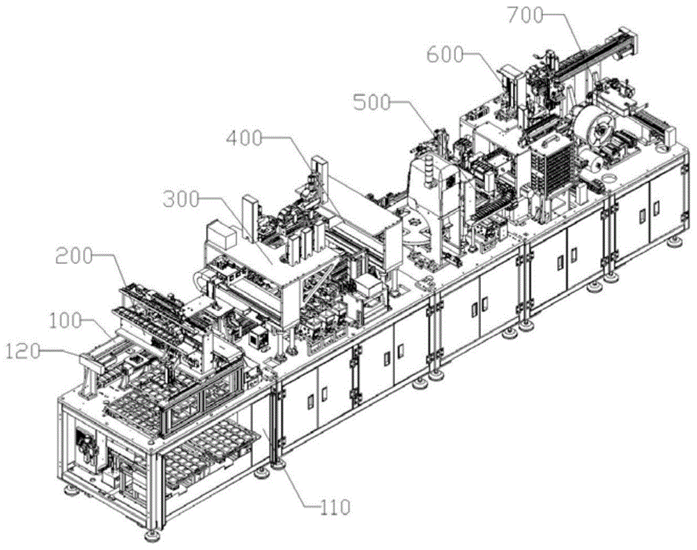
图1为本发明一种散热风扇组装流水线的总构成图;Fig. 1 is the general structure drawing of a kind of cooling fan assembly line of the present invention;
图2为本发明一种散热风扇组装流水线的上料装置的结构示意图(一);Fig. 2 is a schematic structural view (1) of a feeding device of a cooling fan assembly line of the present invention;
图3为本发明一种散热风扇组装流水线的上料装置的结构示意图(二);Fig. 3 is a structural schematic diagram (2) of a feeding device of a cooling fan assembly line of the present invention;
图4为本发明一种散热风扇组装流水线的垫圈及耐磨片组装装置的结构示意图(一);Fig. 4 is a structural schematic diagram (1) of a washer and a wear-resistant plate assembly device of a heat dissipation fan assembly line of the present invention;
图5为本发明一种散热风扇组装流水线的垫圈及耐磨片组装装置的结构示意图(二);Fig. 5 is a structural schematic diagram (2) of a washer and a wear-resistant plate assembly device of a heat dissipation fan assembly line of the present invention;
图6为本发明一种散热风扇组装流水线的轴承组装装置的结构示意图(一);Fig. 6 is a structural schematic diagram (1) of a bearing assembly device of a cooling fan assembly line according to the present invention;
图7为本发明一种散热风扇组装流水线的轴承组装装置的结构示意图(二);Fig. 7 is a structural schematic diagram (2) of a bearing assembly device of a cooling fan assembly line according to the present invention;
图8为本发明一种散热风扇组装流水线的铜管组装装置的结构示意图(一);8 is a structural schematic view (1) of a copper tube assembly device of a heat dissipation fan assembly line of the present invention;
图9为本发明一种散热风扇组装流水线的铜管组装装置的结构示意图(二);Fig. 9 is a structural schematic diagram (2) of a copper tube assembly device of a cooling fan assembly line according to the present invention;
图10为本发明一种散热风扇组装流水线的定子组装装置的结构示意图(一);Fig. 10 is a structural schematic diagram (1) of a stator assembly device of a cooling fan assembly line according to the present invention;
图11为本发明一种散热风扇组装流水线的定子组装装置的结构示意图(二);Fig. 11 is a structural schematic diagram (2) of a stator assembly device of a cooling fan assembly line according to the present invention;
图12为本发明一种散热风扇组装流水线的贴标装置的结构示意图(一);Fig. 12 is a structural schematic diagram (1) of a labeling device of a cooling fan assembly line according to the present invention;
图13为本发明一种散热风扇组装流水线的贴标装置的结构示意图(二);Fig. 13 is a structural schematic diagram (2) of a labeling device of a cooling fan assembly line according to the present invention;
其中,100、运输装置;110、机架;120、运输丝杆模组;121、第一运输丝杆模组;122、第二运输丝杆模组;123、第三运输丝杆模组;124、第四运输丝杆模组;125、第五运输丝杆模组;126、第六运输丝杆模组;131、清洁组件;132、上料回收部;133、第一点油组件;134、第一搬运部;135、第二搬运部;136、第二点油组件;137、点油检测组件;138、第二回收部;139、第三搬运部;1310、第三回收部;1311、底座吸取部;140、转台组件;141、第二加工位;142、载板;143、第二通孔;Among them, 100, transportation device; 110, frame; 120, transportation screw module; 121, first transportation screw module; 122, second transportation screw module; 123, third transportation screw module; 124. The fourth transportation screw module; 125. The fifth transportation screw module; 126. The sixth transportation screw module; 131. Cleaning components; 134. The first transport unit; 135. The second transport unit; 136. The second oil spot assembly; 137. The oil spot detection unit; 138. The second recovery unit; 139. The third transport unit; 1310. The third recovery unit; 1311, the suction part of the base; 140, the turntable assembly; 141, the second processing position; 142, the carrier plate; 143, the second through hole;
200、上料装置;210、料盘上料组件;211、料盘上料部;2111、第一支撑架;2112、伸缩气缸;2113、第一传送带;2114、转接板;212、料盘回流部;220、底座转运组件;221、第一吸附部;222、上料驱动件;2221、第二支撑架;2222、X轴上料丝杆模组;2223、X轴上料导轨;2224、Y轴上料丝杆模组;2225、Z轴上料滑台模组;2226、料盘吸附部;223、Y轴相机模组;224、第一上料相机;230、第一检测组件;240、第一料盘升降部;250、第二料盘升降部;200, feeding device; 210, tray feeding assembly; 211, tray loading part; 2111, first support frame; 2112, telescopic cylinder; 2113, first conveyor belt; 2114, adapter plate; 212,
300、垫圈及耐磨片组装装置;310、垫圈及耐磨片上料组件;311、耐磨片及垫圈装料部;3111、耐磨片震动盘;3112、垫圈震动盘;3113、缓存料盒;3114、直震;3115、离子风棒;3116、耐磨片料盒;3117、垫圈料盒;3118、备用料盒;312、第二上料相机;320、垫圈及耐磨片组装组件;321、耐磨片吸附部;322、垫圈吸附部;323、第一驱动件;3231、第三支撑架;3232、第一Y轴丝杆模组;3233、第一X轴丝杆模组;3234、第一固定座;3235、耐磨片滑台模组;3236、垫片滑台模组;3237、备用滑台模组;324、第一定位相机;325、耐磨片及垫圈加工位;326、备用吸附部;300. Washer and wear-resistant sheet assembly device; 310. Washer and wear-resistant sheet feeding assembly; 311. Wear-resistant sheet and gasket loading part; 3111. Wear-resistant sheet vibration plate; 3112. Washer vibration plate; 3113. Buffer material box ; 3114, direct shock; 3115, ion wind rod; 3116, wear-resistant sheet material box; 3117, gasket material box; 3118, spare material box; 312, second feeding camera; 321, wear-resistant sheet adsorption part; 322, washer adsorption part; 323, first driving member; 3231, third support frame; 3232, first Y-axis screw module; 3233, first X-axis screw module; 3234, the first fixed seat; 3235, the wear-resistant sheet sliding table module; 3236, the gasket sliding table module; 3237, the spare sliding table module; 324, the first positioning camera; 325, the wear-resistant sheet and the gasket processing position ; 326, spare adsorption part;
400、轴承组装装置;410、轴承装料组件;420、轴承压合组件;421、导向部;4211、导向丝杆模组;4212、导向滑台模组;4213、轴承限位板;4214、导向柱;422、轴承夹持部;423、轴承压合部;424、第二驱动件;4241、第四支撑架;4242、第二Y轴丝杆模组;4243、第二X轴丝杆模组;4244、第二Z轴滑台模组;4245、第二固定座;430、第一加工位;431、导向孔;440、第一转运组件;400. Bearing assembly device; 410. Bearing loading assembly; 420. Bearing pressing assembly; 421. Guide part; 4211. Guide screw module; 4212. Guide slide module; 4213. Bearing limit plate; 4214. Guide column; 422, bearing clamping part; 423, bearing pressing part; 424, second driving part; 4241, fourth support frame; 4242, second Y-axis screw module; 4243, second X-axis screw Module; 4244, second Z-axis slide module; 4245, second fixing seat; 430, first processing position; 431, guide hole; 440, first transfer assembly;
500、铜管组装装置;510、铜管上料组件;511、铜管夹持部;512、第三驱动件;5121、第五支撑架;5122、第三X轴丝杆模组;5123、第二X轴导轨;5124、第三Y轴丝杆模组;5125、第三Z轴滑台模组;513、第二定位相机;520、预压合组件;521、预压合轴;522、凸轮轴承随动器;523、斜面滑块;524、水平气缸;530、铜管压合组件;531、压合部;532、压床;533、压头;540、第二检测组件;541、高度检测滑台模组;542、量仪;500. Copper tube assembly device; 510. Copper tube feeding assembly; 511. Copper tube clamping part; 512. The third driving member; 5121. The fifth support frame; 5122. The third X-axis screw module; 5123. The second X-axis guide rail; 5124, the third Y-axis screw module; 5125, the third Z-axis slide module; 513, the second positioning camera; 520, the pre-press assembly; 521, the pre-press shaft; 522 , Cam bearing follower; 523, Inclined slider; 524, Horizontal cylinder; 530, Copper pipe pressing assembly; 531, Pressing part; , height detection sliding table module; 542, measuring instrument;
600、定子组装装置;610、定子转运组件;611、电动平移台;612、电动旋转台;613、定子转运模组;620、第三检测组件;630、定子压合组件;631、第三加工位;632、定子压合部;633、电缸;640、第四检测组件;650、定子上料组件;660、定子夹持组件;661、定子夹持部;662、第四驱动件;6621、第六支撑架;6622、第四Y轴丝杆模组;6623、第四X轴丝杆模组;6624、第四Z轴滑台模组;600. Stator assembly device; 610. Stator transfer assembly; 611. Electric translation table; 612. Electric rotation table; 613. Stator transfer module; 620. Third detection component; 630. Stator pressing assembly; 631. Third processing position; 632, stator pressing part; 633, electric cylinder; 640, fourth detection component; 650, stator feeding component; 660, stator clamping component; 661, stator clamping part; 662, fourth driving part; 6621 , the sixth support frame; 6622, the fourth Y-axis screw module; 6623, the fourth X-axis screw module; 6624, the fourth Z-axis slide module;
700、贴标装置;710、取标组件;711、标签飞达;712、标签剥离位;720、转运贴标组件;721、标签吸取部;722、旋转电机;723、标签转运丝杆模组;724、标签转运滑台模组;725、旋转气缸;726、L型固定板;730、第五检测组件。700. Labeling device; 710. Label taking component; 711. Label feeder; 712. Label peeling position; 720. Transfer labeling component; 721. Label suction part; 722. Rotating motor; 723. Label transfer screw module ; 724, the label transfer slide module; 725, the rotary cylinder; 726, the L-shaped fixed plate; 730, the fifth detection component.
具体实施方式detailed description
下面将结合本发明中的附图,对本发明实施例中的技术方案进行清楚、完整的描述,显然,所描述的实施例仅仅是本发明一部分实施例,而不是全部的实施例。基于本发明中的实施例,本领域普通的技术人员在没有做出创造性劳动的前提下所获得的所有其它实施例,都属于本发明的保护范围。The technical solutions in the embodiments of the present invention will be clearly and completely described below in conjunction with the drawings in the present invention. Apparently, the described embodiments are only some of the embodiments of the present invention, not all of them. Based on the embodiments of the present invention, all other embodiments obtained by persons of ordinary skill in the art without making creative efforts belong to the protection scope of the present invention.
结合附图1至附图13及具体实施例详细论述本发明;为方便理解,设运输装置100运输方向为X轴方向,垂直运输装置100运输方向为Y轴方向,竖直方向为Z轴方向:The present invention is discussed in detail in conjunction with accompanying drawing 1 to accompanying drawing 13 and specific embodiment; For convenience of understanding, suppose the transporting direction of transporting
如图1至图13所示的一种散热风扇组装流水线,包括机架110、用于风扇底座流水线加工的运输装置100,还包括依次沿运输装置100运输方向排布的上料装置200、垫圈及耐磨片组装装置300、轴承组装装置400、铜管组装装置500、定子组装装置600;上料装置200包括用于将风扇底座转运至运输装置100的料盘上料组件210、用于自料盘上料组件210搬运风扇底座至运输装置100的底座转运组件220、朝向运输装置100用于对风扇底座进行质检的第一检测组件230;垫圈及耐磨片组装装置300包括垫圈及耐磨片上料组件310、移动于垫圈及耐磨片上料组件310和运输装置100之间的垫圈及耐磨片组装组件320;轴承组装装置400包括轴承装料组件410、移动于轴承装料组件410和运输装置100之间用于搬运和压合轴承的轴承压合组件420;铜管组装装置500包括沿运输装置100依次分布的铜管上料组件510、与铜管上料组件510配合对铜管合风扇底座进行预压合的预压合组件520、铜管压合组件530和用于检测铜管压合高度的第二检测组件540;定子组装装置600包括定子转运组件610、朝向定子转运组件610用于检测定子安装位置和角度的第三检测组件620、沿运输装置100运输方向架设在运输装置100上方的定子压合组件630和用于检测定子压合高度的第四检测组件640;其中,风扇底座自上料装置200上料至运输装置100上,风扇底座依次运输到垫圈及耐磨片组装装置300、轴承组装装置400、铜管组装装置500、定子组装装置600和贴标装置700上进行相应的加工,从而实现散热风扇的全自动化流水线组装,减少人力成本,提高了加工效率;同时第一检测组件230对风扇底座上料进行质检及不合格产品回收、第二检测组件540对铜管组装后的铜管压合高度进行检测及对不合格的风扇底座进行回收,第四检测组件640对风扇底座上定子组装后的定子压合高度进行检测及对不合格的风扇底座进行回收,从而减小了废品量产出,提高了风扇底座的总加工质量;轴承压合组件420的导向部421在轴承压合时提供轴承压合导向,使轴承沿着导向部421压合至风扇底座,预压合组件520通过对铜管进行预压合,防止铜管倾斜安装或安装不实、第三检测组件620检测定子的角度并通讯定子转运组件610对定子的安装位置和角度进行调整,保证定子每次的安装位置和角度相同,提高散热风扇底座加工的一致性,提高了散热风扇组的零部件组装精度。A heat dissipation fan assembly line as shown in Figures 1 to 13 includes a
具体的,如图2、图3所示,料盘上料组件210包括升降于机架110内部和机架110顶部之间的料盘上料部211、料盘回流部212,底座转运组件220包括设于机架110上方的第一吸附部221、设于机架110顶部并驱动第一吸附部221调整位置和高度的上料驱动件222,第一吸附部221移动于料盘上料部211和运输装置100之间;其中,料盘上料组件210用于将载有风扇底座的料盘转运至机架顶部以及将空的料盘转运回收至上料装置200外,料盘上料部211和料盘回流部212均包括安装在机架110底板上的第一支撑架2111、安装在第一支撑架2111上的伸缩气缸2112、安装在第一支撑架2111顶部第一传送带2113和与第一传送带2113同水平面的转接板2114,料盘上料组件210还包括第一料盘升降部240和第二料盘升降部250,第一料盘升降部240和第二料盘升降部250分别带动料盘上料部211和料盘回流部212升降;第一传送带2113水平放置,第一传送带2113与转接板2114位于同一高度,伸缩气缸2112的伸缩端与转接板2114底部铰接;其中,转接板2114为料盘放置和回收的载体,料盘回流部212的第一传送带2113和料盘上料部211的第一传送带2113运动方向相反;当向装置输送料盘时,外部AVG机器人将料盘放置在转接板2114后,料盘在转接板2114的后端与第一传送带2113接触,因第一传送带2113和料盘底部的接触,第一传送带2113带动料盘向第一料盘升降部240方向运动;当装置向外部输送空的料盘时,第二料盘升降部250将机架110顶部的空的料盘运输到料盘回流部212上,料盘与料盘回流部212的第一传送带2113接触后,第一传送带2113带动料盘向料盘回流部212的转接板2114运输,当料盘运输至转接板2114时,对应的伸缩气缸2112收缩,将转接板2114向外翻转,料盘沿着转接板2114向外滑落到机架110外设置的料盘回收位上;通过料盘上料部211和料盘回流部212实现料盘的自动化上下料,减少人力成本。Specifically, as shown in FIG. 2 and FIG. 3 , the
具体的,其中上料驱动件222包括第二支撑架2221、X轴上料丝杆模组2222以及X轴上料导轨2223、第二支撑架2221架设在X轴上料丝杆模组2222和X轴上料导轨2223之间并与X轴上料丝杆模组2222和X轴上料导轨2223滑动连接的Y轴上料丝杆模组2224、滑动连接在Y轴上料丝杆模组2224的Z轴上料滑台模组2225,第一吸附部221与Z轴上料滑台模组2225升降连接,第二支撑架2221底部还设有移动于第一料盘升降部240和第二料盘升降部250的料盘吸附部2226,第二支撑架2221顶部还设有Y轴相机模组223和滑动连接在Y轴相机模组223的第一上料相机224,第一上料相机224竖直朝向第一料盘升降部240方向;运输装置100包括运输丝杆模组120,其中,运输丝杆模组120包括设置在上料装置200一侧的第一运输丝杆模组121,第一吸附部221在上料驱动件222的驱动下,将第一料盘升降部240的风扇底座上料至第一运输丝杆模组121上进行转运;当料盘中的风扇底座均转运完毕后,料盘吸附部2226将第一料盘升降部240上的空料盘吸取,X轴上料丝杆模组2222向第二料盘升降部250运动,料盘吸附部2226释放料盘至第二料盘升降部250,第二料盘升降部250将空的料盘转运至料盘回流部212进行料盘下料。Specifically, wherein the
其中,第一上料相机224用于对料盘中的风扇底座进行定位,根据风扇底座的位置,控制X轴上料丝杆模组2222、Y轴上料丝杆模组2224和Z轴上料滑台模组2225运转,从而引导第一吸附部221移动至风扇底座的位置进行吸取;从而实现风扇底座转运过程中的精准定位,提高了上料的精度。Wherein, the
具体的,第一运输丝杆模组121沿运输方向依次排布有清洁组件131、第一检测组件230、上料回收部132;清洁组件131用于对风扇底座上的污渍进行除尘和清理;第一检测组件230用于检测第一运输丝杆模组121上的风扇底座是否符合质量标准和清洁标准,当第一检测组件230检测风扇底座不符合标准时,第一检测组件230通讯至上料回收部132对不合格的风扇底座进行转运,从而对不合格的风扇底座进行回收,实现自动对不合格的风扇底座的转运处理,使风扇底座的质量一致性好,节省了人工成本。Specifically, the first
具体的,如图4、图5所示,垫圈及耐磨片上料组件310包括耐磨片及垫圈装料部311、朝向耐磨片及垫圈装料部311的若干第二上料相机312;垫圈及耐磨片组装组件320包括耐磨片吸附部321、垫圈吸附部322和调整耐磨片吸附部321以及垫圈吸附部322位置和高度的第一驱动件323和朝向运输装置100的第一定位相机324,耐磨片吸附部321和垫圈吸附部322移动于耐磨片及垫圈装料部311和运输装置100之间,第一定位相机324和第二上料相机312与第一驱动件323通讯连接。Specifically, as shown in Fig. 4 and Fig. 5, the washer and wear-resistant
其中,运输丝杆模组120还包括设置在耐磨片及垫圈组装装置一侧的第二运输丝杆模组122以及第一点油组件133,第一点油组件133位于耐磨片及垫圈加工位325的前段,用于对风扇底座进行点油,减小耐磨片安装后的运转摩擦力;耐磨片及垫圈装料部311包括耐磨片震动盘3111、垫圈震动盘3112、若干与耐磨片震动盘3111、垫圈震动盘3112对应设置的缓存料盒3113、若干与耐磨片震动盘3111、垫圈震动盘3112对应传动连接的直震3114和安装在缓存料盒3113上的离子风棒3115,缓存料盒3113的出料口朝向耐磨片震动盘3111或垫圈震动盘3112,缓存料盒3113安装在直震3114上;缓存料盒3113包括耐磨片料盒3116、垫圈料盒3117和备用料盒3118,还包括与备用料盒3118对应设置的备用震动盘,备用料盒3118用于承装备用的垫圈,人工将耐磨片、垫圈分别放入缓存料盒3113,通过直震3114将耐磨片和垫圈分别放入耐磨片震动盘3111和垫圈震动盘3112,然后耐磨片震动盘3111和垫圈震动盘3112分别将耐磨片和垫圈震散;第二上料相机312与第一驱动件323通讯连接;第二上料相机312用于检测震散后的耐磨片和垫圈的位置,通过第二上料相机312对耐磨片震动盘3111、垫圈震动盘3112和备用震动盘进行拍照,确定耐磨片、垫圈的排布,获取耐磨片和垫圈的平面坐标并将平面坐标通讯至第一驱动件323,第一驱动件323根据平面坐标驱动耐磨片吸附部321和垫圈吸附部322向待取耐磨片和垫圈的上方运动,并驱动耐磨片吸附部321和垫圈吸附部322下降分别吸取耐磨片和垫圈,从而实现耐磨片和垫圈的精确上料,提高了耐磨片和垫圈的夹取效率;离子风棒3115安装在耐磨片震动盘3111、垫圈震动盘3112和备用震动盘的上方,离子风棒3115的出风口可以度调整,离子风棒3115用于消除震动过程中产生的静电。Wherein, the
具体的,垫圈及耐磨片组装组件320还包括位于第二运输丝杆模组122一侧的耐磨片及垫圈加工位325,运输丝杆模组120还包括移动于耐磨片及垫圈加工位325和第二运输丝杆模组122之间的第一搬运部134,第一搬运部134用于将第二运输丝杆模组122未加工的风扇底座搬运至耐磨片及垫圈加工位325以及将耐磨片及垫圈加工位325加工后的风扇底座搬运至第二运输丝杆模组122;第一驱动件323包括第三支撑架3231、安装在第三支撑架3231上的第一Y轴丝杆模组3232、与第一Y轴丝杆模组3232滑动连接的第一X轴丝杆模组3233、与第一X轴丝杆模组3233滑动连接的第一固定座3234、竖直安装在第一固定座3234上的耐磨片滑台模组3235和垫片滑台模组3236,耐磨片吸附部321和垫圈吸附部322分别与耐磨片滑台模组3235和垫片滑台模组3236升降连接;还包括备用吸附部326,备用吸附部326用于在垫圈吸附部322无法运作时替代垫圈吸附部322使用,备用滑台模组安装在第一固定座3234上,备用吸附部326安装在备用滑台模组上,备用吸附部326在备用滑台模组上升降,备用吸附部326与垫圈吸附部322结构相同,在此不再赘述;当需要吸取耐磨片和垫圈时,第一Y轴丝杆模组3232驱动第一X轴丝杆模组3233移动至耐磨片及垫圈装料部311上方,第一X轴丝杆模组3233上的耐磨片滑台模组3235和垫片滑台模组3236随着对第一固定座3234的移动在沿X轴方向移动,耐磨片吸附部321和垫圈吸附部322下降并分别吸附耐磨片和垫圈;在耐磨片和垫圈吸附后,耐磨片吸附部321和垫圈吸附部322上升,第一Y轴丝杆模组3232驱动第一X轴丝杆模组3233移动至耐磨片及垫圈加工位325上方,耐磨片吸附部321和垫圈吸附部322依次将耐磨片和垫圈安装在风扇底座上。Specifically, the washer and wear-resistant
具体的,第一定位相机324安装在第三支撑架3231顶部并朝向耐磨片及垫圈加工位325,第一定位相机324用于检测风扇底座上耐磨片和垫圈需要安装的位置,并将位置信息通讯至第一驱动件323,第一驱动件323分别驱动耐磨片吸附部321和垫圈吸附部322将耐磨片和垫圈精确安装在风扇底座的对应位置,从而实现将耐磨片和垫圈精确安装在风扇底座的对应位置,提高了产品的一致性,便于后续程序对产品的进一步加工。Specifically, the
具体的,如图6、图7所示轴承组装装置400还包括第一加工位430、移动于第一加工位430和运输装置100之间的第一转运组件440,轴承压合组件420包括导向部421、轴承夹持部422、轴承压合部423和调整轴承夹持部422及轴承压合部423位置和高度的第二驱动件424;导向部421包括导向丝杆模组4211、与导向丝杆模组4211滑动连接的导向滑台模组4212、升降于导向滑台模组4212的轴承限位板4213和安装在轴承限位板4213底部的导向柱4214;第一加工位430上开设有导向孔431,导向柱4214升降在导向孔431内,轴承限位板4213上开设有第一通孔;轴承夹持部422移动于轴承装料组件410和第一加工位430之间,轴承压合部423与第一通孔同轴。Specifically, as shown in Figures 6 and 7, the bearing
其中,运输丝杆模组120包括设置在轴承组装装置400一侧的第三运输丝杆模组123,第一转运组件440用于将未加工的风扇底座自第三运输丝杆模组123搬运至第一加工位430以及将加工后的风扇底座自第一加工位430搬运至第三运输丝杆模组123;第二驱动件424包括第四支撑架4241、安装在第四支撑架4241上的第二Y轴丝杆模组4242、与第二Y轴丝杆模组4242滑动连接的第二X轴丝杆模组4243、滑动连接在第二X轴丝杆模组4243的第二Z轴滑台模组4244、升降在第二Z轴滑台模组4244上的第二固定座4245,轴承夹持部422和轴承压合部423安装在第二固定座4245底部;第一转运组件440将未加工的风扇底座转运至第一加工位430,当需要夹持和转运轴承时,第二Y轴丝杆模组4242驱动第二X轴丝杆模组4243向轴承装料组件410方向移动,第二X轴丝杆模组4243移动,第二固定座4245下的轴承夹持部422将夹取间隙的轴承进行夹取,轴承夹取后Y轴电机驱动第二X轴丝杆模组4243向轴承压合部423移动,轴承夹持部422将轴承转运至第一加工位430的风扇底座对应的轴承压合位置的正上方,并将轴承安装至导向部421;导向滑台模组4212驱动导向滑台模组4212向第一加工位430方向移动,当导向块的第一导向柱4214位于第一加工位430的导向孔431正上方时,轴承限位板4213和安装在轴承限位板4213底部的导向柱4214下降,导向柱4214插入导向孔431中,第一通孔套接在风扇底座的垫圈上;轴承夹持部422将轴承放置在轴承限位件上,轴承、第一通孔和风扇底座的垫圈同轴,此时轴承压合部423下降,将轴承压合至垫圈内,而后第一转运组件440将加工后的风扇底座搬运至第三运输丝杆模组123;导向部421在压合过程中起到导向作用,从而提高轴承压合的精确性,提高产品的一致性。Wherein, the transport screw module 120 includes a third transport screw module 123 arranged on one side of the bearing assembly device 400, and the first transfer assembly 440 is used to transport the unprocessed fan base from the third transport screw module 123 To the first processing position 430 and transport the processed fan base from the first processing position 430 to the third transport screw module 123; the second driving member 424 includes a fourth support frame 4241, installed on the fourth support frame 4241 The second Y-axis screw module 4242, the second X-axis screw module 4243 that is slidably connected to the second Y-axis screw module 4242, the second Z that is slidably connected to the second X-axis screw module 4243 The shaft slide module 4244, the second fixed seat 4245 that is lifted and lowered on the second Z-axis slide module 4244, the bearing clamping part 422 and the bearing pressing part 423 are installed at the bottom of the second fixed seat 4245; the first transfer assembly 440 transfers the unprocessed fan base to the first processing position 430, when the bearing needs to be clamped and transferred, the second Y-axis screw module 4242 drives the second X-axis screw module 4243 to the direction of the bearing loading assembly 410 Move, the second X-axis screw module 4243 moves, the bearing clamping part 422 under the second fixed seat 4245 clamps the bearing in the clamping gap, and after the bearing is clamped, the Y-axis motor drives the second X-axis screw module The group 4243 moves to the bearing pressing part 423, and the bearing clamping part 422 transfers the bearing to the position directly above the bearing pressing position corresponding to the fan base of the first processing position 430, and installs the bearing to the guide part 421; The group 4212 drives the guide slide module 4212 to move towards the first processing position 430. When the
具体的,如图8、图9所示铜管上料组件510包括铜管夹持部511和调整铜管夹持部511高度和位置的第三驱动件512;运输装置100包括转台组件140,转台组件140包括若干第二加工位141、放置在第二加工位141上的载板142和开设在第二加工位141上的第二通孔143;预压合组件520包括位于通孔下方的升降轴,升降轴、载板142和铜管夹持部511同轴;其中,运输丝杆模组120包括设置在铜管组装装置500的一侧的第四运输丝杆模组124以及移动于第四运输丝杆模组124和转台组件140之间的第二搬运部135;优选的,第二加工位141设置为四个,四个第二加工位141分别对应第二搬运部135、铜管上料组件510、铜管压合组件530和第二检测组件540。Specifically, as shown in FIG. 8 and FIG. 9, the copper
其中,第三驱动件512包括第三X轴丝杆模组5122和第二X轴导轨5123、架设在第二X轴导轨5123和第三X轴丝杆模组5122之间并与第二X轴导轨5123和第三X轴丝杆模组5122滑动连接的第五支撑架5121、安装在第五支撑架5121上垂直于第二X轴导轨5123设置的第三Y轴丝杆模组5124、与第三Y轴丝杆模组5124滑动连接的第三Z轴滑台模组5125,铜管夹持部511与第三Z轴滑台模组5125在竖直方向上滑动连接;第五支撑架5121移动于铜管上料组件510和第二加工位141之间,第三Z轴滑台模组5125用于带动铜管夹持部511升降,实现铜管夹持部511位置高度可调;铜管夹持部511自铜管上料组件510夹取铜管后沿着第三Z轴滑台模组5125上升,而后铜管夹持部511通过位置调整至第二加工位141上方,第三Z轴滑台模组5125驱动铜管夹持部511下降,铜管夹持部511将铜管安放至风扇底座的对应位置,从而实现铜管的安放;优选的,铜管取料组件上方还安装有第二定位相机513,第二定位相机513与第三X轴丝杆模组5122和第三Y轴丝杆模组5124通讯连接。Wherein, the
预压合组件520包括可升降的预压合轴521,预压合轴521位于第二加工位141下方,第二加工位141中心位置设有第二通孔143,预压合轴521与第二通孔143同轴,第二通孔143上放置有用于承载风扇底板的载板142,预压合轴521穿过第二通孔143与铜管夹持部511同轴;预压合组件520还包括设置在预压合轴521底部的凸轮轴承随动器522、与凸轮轴承随动器522滚动连接的斜面滑块523、与斜面滑块523伸缩连接的水平气缸524;当铜管夹持部511将铜管夹取至铜管加工位上方后,水平气缸524伸展,凸轮轴承随动器522沿斜面滑块523向上滚动,带动预压合轴521上升,预压合轴521上升穿过第二通孔143将载板142顶起,载板142离开原位置上升,同时铜管夹持部511将铜管套接在风扇底座的轴承上,铜管夹持部511向下对风扇底座提供一个下压的力,预压合轴521对风扇底座提供一个向上的力,两个相对的力对风扇底座和铜管进行预压合处理,使铜管和风扇底座的轴承之间贴合,当风扇底座和铜管预压合不到位时,微调铜管夹持部511至风扇底座和铜管成功预压合,保证铜管竖直安装在风扇底座的铜管安装位上,避免出现铜管斜向安装等安装不到位的情况,提高后续压合操作的铜管压合效果,以及提高铜管的组装精度;优选的,铜管压合组件530包括用于压合轴承的压床532和位于第二加工位141底部的可升降的压合部531,其中压合部531和预压合组件520结构相同,在此不再赘述,压床532驱动压床532的压头533下压,压合部531上升将载板142顶起并与压头533配合将铜管压合进风扇底座中,压合部531保证压合时受力不在转台组件140上,保证转台转台旋转时的稳定性。The pre-pressing assembly 520 includes a liftable
具体的,第二检测组件540包括竖直移动的高度检测滑台模组541和与高度检测滑台模组541滑动连接的量仪542,量仪542的接触式传感器朝向第二加工位141;第二检测组件540用于检测铜管压合后的高度,其中量仪542的接触式传感器数量为两个,接触式传感器垂直于铜管的直径,其中一只接触式传感器测量风扇底座所处载板142的高度,另一只接触式传感器测量铜管顶部的高度,从而得出铜管与风扇底座底面之间的相对高度;运输装置100还包括架设在第四运输丝杆模组124位于转台组件140后端依次设置的第二点油组件136、点油检测组件137、第二回收部138,第二回收部138和第二检测组件540和点油检测组件137通讯连接,第二回收部138用于对铜管压合高度不合格及点油不合格的产品进行转运回收处理。Specifically, the
具体的,如图10、图11所示定子组装装置600还包括定子上料组件650和定子夹持组件660,定子夹持组件660包括定子夹持部661和调整定子夹持部661高度和位置自定子上料组件650向定子转运组件610上料的第四驱动件662;定子转运组件610包括用于调整定子安装位置电动平移台611、安装在电动平移台611上用于调整定子安装角度的电动旋转台612、用于将定子向定子压合组件630转运的定子转运模组613,电动平移台611与定子转运组件610滑动连接。Specifically, as shown in Fig. 10 and Fig. 11 , the
其中,定子压合组件630包括第三加工位631,运输丝杆模组120包括设置在定子组装装置600一侧的第五运输丝杆模组125、移动于第三加工位631和第五运输丝杆模组125的第三搬运部139;第四驱动件662包括第六支撑架6621、第四X轴丝杆模组6623、与第四X轴丝杆模组6623滑动连接的第四Y轴丝杆模组6622、与第四Y轴丝杆模组6622滑动连接的第四Z轴滑台模组6624,定子夹持部661与第四Z轴滑台模组6624升降连接;第四X轴丝杆模组6623和第四Y轴丝杆模组6622用于调整定子夹持部661的在X、Y轴平面上的位置,定子夹持部661自定子上料组件650上夹取定子,在夹取定子后,第四Y轴丝杆模组6622带动第四Z轴滑台模组6624上的定子夹持部661向定子输送部转运,从而完成定子取料程序;定子夹取部将定子释放至电动旋转台612上,定子转运模组613驱动电动平移台611和电动旋转台612向定子压合组件630转运,第三检测组件620对定子的安装位置和角度进行检测,并通讯至电动位移台和电动旋转台612将定子调整到适合的位置和角度,当角度调整完毕后,定子转运模组613继续向压合组件输送定子;优选的,定子压合组件630包括定子压合部632和驱动定子压合部632升降的电缸633,第三搬运部139将第五运输丝杆模组125上未加工的风扇底座转运至第三加工位631,定子压合部632对定子夹取,同时定子转运模组613远离第三加工位631为定子压合部632压合提供升降空间,定子压合部632下降并将定子压合至风扇底座中;第四检测组件640用于检测定子的压合高度,运输装置100包括设置在第五运输丝杆模组125一侧的第三回收部1310,第三回收部1310位于第三搬运部139的后段,当第四检测组件640检测到定子压合高度不符合质量标准后,第四检测组件640通讯至第三搬运部139对不合格的风扇底座进行转运回收处理。Wherein, the
具体的,如图12、图13所示贴标装置700包括取标组件710、移动于运输装置100和取标组件710之间的转运贴标组件720、朝向取标组件710用于检测标签角度的第五检测组件730,转运贴标组件720包括标签吸取部721以及与标签吸取部721旋转连接的旋转电机722,第五检测组件730与旋转电机722通讯连接。Specifically, as shown in Figure 12 and Figure 13, the
具体的,转运贴标组件720还包括标签转运丝杆模组723、与标签转运丝杆模组723滑动连接的标签转运滑台模组724、与标签转运滑台模组724升降连接的旋转气缸725、L型固定板726,L型固定板726的侧端与旋转气缸725旋转连接,旋转电机722与L型固定板726的底端固定连接。Specifically, the
其中,运输丝杆模组120包括设置在贴标装置700一侧的第六运输丝杆模组126和滑动连接在第六运输丝杆模组126的底座吸取部1311,底座吸取部1311自第五运输丝杆模组125上吸取风扇底座并向转运贴标组件720转运,第六运输丝杆模组126沿X轴设置;取标组件710包括标签飞达、位于标签飞达底部的标签剥离位,第五检测组件730朝向标签剥离位对标签进行定位和角度记录,并根据设定的标签角度与第五检测组件730记录的角度计算角度偏移量,第五检测组件730将角度偏移量通讯至旋转电机722,旋转电机722根据角度偏移量进行旋转,从而保证标签贴在风扇的角度具有一致性;标签转运滑台模组724用于调整标签吸取部721在Z轴上的位置,标签转运丝杆模组723用于将标签吸取部721向底座吸取部1311转运,标签转运丝杆模组723沿Y轴设置;当标签吸取部721吸取标签后,标签转运模组驱动标签吸取部721向底座吸取部1311转运,同时旋转气缸725带动L型固定板726沿X轴旋转180度,使标签的粘贴部和风扇底座的底部相对,旋转电机722调整标签吸取部721的角度,当标签吸取部721将标签转运至底座吸取部1311下方后,标签吸取部721下降,将风扇底座的底部和标签贴合,完成贴标程序,底座吸取部1311继续沿运输装置100的运输方向输送至下一加工位进行加工。Wherein, the
具体的,第一检测组件230、第三检测组件620、第四检测组件640和第五检测组件730均为CCD相机。Specifically, the
以上借助具体实施例对本发明做了进一步描述,但是应该理解的是,这里具体的描述,不应理解为对本发明的实质和范围的限定,本领域内的普通技术人员在阅读本说明书后对上述实施例做出的各种修改,都属于本发明所保护的范围。The present invention has been further described above with the help of specific embodiments, but it should be understood that the specific description herein should not be construed as limiting the spirit and scope of the present invention. Various modifications made in the embodiments all belong to the protection scope of the present invention.
Claims (10)
Priority Applications (1)
| Application Number | Priority Date | Filing Date | Title |
|---|---|---|---|
| CN202211199281.9A CN115520594B (en) | 2022-09-29 | 2022-09-29 | Radiator fan assembly line |
Applications Claiming Priority (1)
| Application Number | Priority Date | Filing Date | Title |
|---|---|---|---|
| CN202211199281.9A CN115520594B (en) | 2022-09-29 | 2022-09-29 | Radiator fan assembly line |
Publications (2)
| Publication Number | Publication Date |
|---|---|
| CN115520594A true CN115520594A (en) | 2022-12-27 |
| CN115520594B CN115520594B (en) | 2025-12-19 |
Family
ID=84700477
Family Applications (1)
| Application Number | Title | Priority Date | Filing Date |
|---|---|---|---|
| CN202211199281.9A Active CN115520594B (en) | 2022-09-29 | 2022-09-29 | Radiator fan assembly line |
Country Status (1)
| Country | Link |
|---|---|
| CN (1) | CN115520594B (en) |
Cited By (8)
| Publication number | Priority date | Publication date | Assignee | Title |
|---|---|---|---|---|
| CN116748828A (en) * | 2023-06-21 | 2023-09-15 | 浙江汽车仪表有限公司 | Suspension type new energy automobile instrument panel assembly and assembly device thereof |
| CN117300568A (en) * | 2023-11-13 | 2023-12-29 | 格力电器(石家庄)有限公司 | Assembly equipment |
| CN118357717A (en) * | 2024-05-06 | 2024-07-19 | 安徽澳扬自动化设备有限公司 | Axial flow fan automatic assembly line |
| CN118372019A (en) * | 2024-05-11 | 2024-07-23 | 广东奇创智能科技有限公司 | A bearing assembly line |
| CN119389701A (en) * | 2024-12-04 | 2025-02-07 | 东莞市雄创自动化机械有限公司 | Fan body assembly labeling machine |
| CN119820298A (en) * | 2024-12-27 | 2025-04-15 | 东莞市星亮科技有限公司 | Rotary assembling mechanism and assembling method for radiating fan |
| CN120190589A (en) * | 2025-05-23 | 2025-06-24 | 昆山可腾电子有限公司 | A server cooling fan module assembly device |
| CN120516405A (en) * | 2025-07-24 | 2025-08-22 | 苏州元脑智能科技有限公司 | Fan automatic assembly line |
Citations (8)
| Publication number | Priority date | Publication date | Assignee | Title |
|---|---|---|---|---|
| US20150275906A1 (en) * | 2014-03-31 | 2015-10-01 | Delta Electronics, Inc. | Thin fan, electronic system and manufacturing method of thin fan |
| CN105729110A (en) * | 2016-04-07 | 2016-07-06 | 肇庆晟辉电子科技有限公司 | Full-automatic robot intelligent production line and manufacturing method for cooling fan |
| CN109128813A (en) * | 2018-10-09 | 2019-01-04 | 留丹翠 | A kind of process units of the flabellum mounting device produced for chip cooling fan and radiator fan |
| CN112682362A (en) * | 2020-06-20 | 2021-04-20 | 东莞市诺辉自动化机械有限公司 | Automatic assembling machine for cooling fan |
| CN214080099U (en) * | 2020-12-28 | 2021-08-31 | 东莞百舜机器人技术有限公司 | Hydraulic fan equipment automation equipment |
| CN214610183U (en) * | 2020-09-07 | 2021-11-05 | 格力电器(武汉)有限公司 | Copper pipe clamping device with rotating function |
| CN216959575U (en) * | 2022-03-02 | 2022-07-12 | 东莞市顶睿科技有限公司 | Micro motor framework and fan |
| CN219296429U (en) * | 2022-09-29 | 2023-07-04 | 东莞市鼎力自动化科技有限公司 | Radiator fan assembly line |
-
2022
- 2022-09-29 CN CN202211199281.9A patent/CN115520594B/en active Active
Patent Citations (8)
| Publication number | Priority date | Publication date | Assignee | Title |
|---|---|---|---|---|
| US20150275906A1 (en) * | 2014-03-31 | 2015-10-01 | Delta Electronics, Inc. | Thin fan, electronic system and manufacturing method of thin fan |
| CN105729110A (en) * | 2016-04-07 | 2016-07-06 | 肇庆晟辉电子科技有限公司 | Full-automatic robot intelligent production line and manufacturing method for cooling fan |
| CN109128813A (en) * | 2018-10-09 | 2019-01-04 | 留丹翠 | A kind of process units of the flabellum mounting device produced for chip cooling fan and radiator fan |
| CN112682362A (en) * | 2020-06-20 | 2021-04-20 | 东莞市诺辉自动化机械有限公司 | Automatic assembling machine for cooling fan |
| CN214610183U (en) * | 2020-09-07 | 2021-11-05 | 格力电器(武汉)有限公司 | Copper pipe clamping device with rotating function |
| CN214080099U (en) * | 2020-12-28 | 2021-08-31 | 东莞百舜机器人技术有限公司 | Hydraulic fan equipment automation equipment |
| CN216959575U (en) * | 2022-03-02 | 2022-07-12 | 东莞市顶睿科技有限公司 | Micro motor framework and fan |
| CN219296429U (en) * | 2022-09-29 | 2023-07-04 | 东莞市鼎力自动化科技有限公司 | Radiator fan assembly line |
Cited By (10)
| Publication number | Priority date | Publication date | Assignee | Title |
|---|---|---|---|---|
| CN116748828A (en) * | 2023-06-21 | 2023-09-15 | 浙江汽车仪表有限公司 | Suspension type new energy automobile instrument panel assembly and assembly device thereof |
| CN116748828B (en) * | 2023-06-21 | 2024-04-12 | 绍兴浙玮汽车电子有限公司 | A suspended new energy vehicle instrument panel assembly and assembly device thereof |
| CN117300568A (en) * | 2023-11-13 | 2023-12-29 | 格力电器(石家庄)有限公司 | Assembly equipment |
| CN118357717A (en) * | 2024-05-06 | 2024-07-19 | 安徽澳扬自动化设备有限公司 | Axial flow fan automatic assembly line |
| CN118372019A (en) * | 2024-05-11 | 2024-07-23 | 广东奇创智能科技有限公司 | A bearing assembly line |
| CN119389701A (en) * | 2024-12-04 | 2025-02-07 | 东莞市雄创自动化机械有限公司 | Fan body assembly labeling machine |
| CN119820298A (en) * | 2024-12-27 | 2025-04-15 | 东莞市星亮科技有限公司 | Rotary assembling mechanism and assembling method for radiating fan |
| CN120190589A (en) * | 2025-05-23 | 2025-06-24 | 昆山可腾电子有限公司 | A server cooling fan module assembly device |
| CN120190589B (en) * | 2025-05-23 | 2025-08-01 | 昆山可腾电子有限公司 | Server radiator fan module equipment |
| CN120516405A (en) * | 2025-07-24 | 2025-08-22 | 苏州元脑智能科技有限公司 | Fan automatic assembly line |
Also Published As
| Publication number | Publication date |
|---|---|
| CN115520594B (en) | 2025-12-19 |
Similar Documents
| Publication | Publication Date | Title |
|---|---|---|
| CN115520594B (en) | Radiator fan assembly line | |
| TWI607940B (en) | Electroplating equipment automatic plate feeder | |
| CN107791022A (en) | An inductor assembly welding and dispensing machine | |
| CN209411201U (en) | A kind of cell piece efficiency detection device | |
| CN107553107A (en) | A kind of continuous automatic assembling of otic placode shell fragment | |
| CN211277258U (en) | A photovoltaic module junction box cover automatic installation equipment | |
| CN212433003U (en) | Automatic detection device for appearance defects of mobile phone iron frame | |
| CN219616140U (en) | Carousel formula AOI check out test set | |
| CN219296429U (en) | Radiator fan assembly line | |
| CN218872930U (en) | Motor shell visual detection equipment | |
| CN210943867U (en) | Loading and unloading machine and production line | |
| CN111359895B (en) | Hub bearing inner wheel demagnetizing, cleaning, measuring and flaw detecting integrated machine | |
| CN218874321U (en) | Fan bearing assembly device | |
| CN211100245U (en) | Magnet transverse device with automatic feeding and discharging functions | |
| CN116460433A (en) | A new energy vehicle fan assembly, welding and testing all-in-one machine | |
| CN116422594A (en) | Turntable AOI testing equipment | |
| CN215542830U (en) | Flexible screen double-sided 3D detection equipment | |
| CN118284025B (en) | Component feeding device and process for assembling PCB | |
| CN210117000U (en) | Automatic carrying and testing device for notebook battery production | |
| CN218533430U (en) | Fan copper pipe compression fittings | |
| CN117340475B (en) | Explosion-proof piece welding machine and working method thereof | |
| CN221464571U (en) | Automatic tester for warpage of PCB (printed circuit board) | |
| CN220063867U (en) | Combined detection carrier and side detection system | |
| CN119187026A (en) | An electronic component quality detection and screening device | |
| CN219553440U (en) | Capacitor processing assembly line |
Legal Events
| Date | Code | Title | Description |
|---|---|---|---|
| PB01 | Publication | ||
| PB01 | Publication | ||
| SE01 | Entry into force of request for substantive examination | ||
| SE01 | Entry into force of request for substantive examination | ||
| GR01 | Patent grant | ||
| GR01 | Patent grant |