CN115502245A - Steel material verticality correcting frame for steel structure building - Google Patents
Steel material verticality correcting frame for steel structure building Download PDFInfo
- Publication number
- CN115502245A CN115502245A CN202211179640.4A CN202211179640A CN115502245A CN 115502245 A CN115502245 A CN 115502245A CN 202211179640 A CN202211179640 A CN 202211179640A CN 115502245 A CN115502245 A CN 115502245A
- Authority
- CN
- China
- Prior art keywords
- steel
- fixedly connected
- plate
- support
- fixed
- Prior art date
- Legal status (The legal status is an assumption and is not a legal conclusion. Google has not performed a legal analysis and makes no representation as to the accuracy of the status listed.)
- Withdrawn
Links
Images


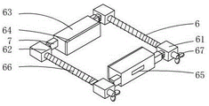

Classifications
-
- B—PERFORMING OPERATIONS; TRANSPORTING
- B21—MECHANICAL METAL-WORKING WITHOUT ESSENTIALLY REMOVING MATERIAL; PUNCHING METAL
- B21D—WORKING OR PROCESSING OF SHEET METAL OR METAL TUBES, RODS OR PROFILES WITHOUT ESSENTIALLY REMOVING MATERIAL; PUNCHING METAL
- B21D3/00—Straightening or restoring form of metal rods, metal tubes, metal profiles, or specific articles made therefrom, whether or not in combination with sheet metal parts
- B21D3/10—Straightening or restoring form of metal rods, metal tubes, metal profiles, or specific articles made therefrom, whether or not in combination with sheet metal parts between rams and anvils or abutments
-
- B—PERFORMING OPERATIONS; TRANSPORTING
- B21—MECHANICAL METAL-WORKING WITHOUT ESSENTIALLY REMOVING MATERIAL; PUNCHING METAL
- B21C—MANUFACTURE OF METAL SHEETS, WIRE, RODS, TUBES, PROFILES OR LIKE SEMI-MANUFACTURED PRODUCTS OTHERWISE THAN BY ROLLING; AUXILIARY OPERATIONS USED IN CONNECTION WITH METAL-WORKING WITHOUT ESSENTIALLY REMOVING MATERIAL
- B21C51/00—Measuring, gauging, indicating, counting, or marking devices specially adapted for use in the production or manipulation of material in accordance with subclasses B21B - B21F
-
- B—PERFORMING OPERATIONS; TRANSPORTING
- B21—MECHANICAL METAL-WORKING WITHOUT ESSENTIALLY REMOVING MATERIAL; PUNCHING METAL
- B21D—WORKING OR PROCESSING OF SHEET METAL OR METAL TUBES, RODS OR PROFILES WITHOUT ESSENTIALLY REMOVING MATERIAL; PUNCHING METAL
- B21D3/00—Straightening or restoring form of metal rods, metal tubes, metal profiles, or specific articles made therefrom, whether or not in combination with sheet metal parts
- B21D3/16—Straightening or restoring form of metal rods, metal tubes, metal profiles, or specific articles made therefrom, whether or not in combination with sheet metal parts of specific articles made from metal rods, tubes, or profiles, e.g. crankshafts, by specially adapted methods or means
-
- B—PERFORMING OPERATIONS; TRANSPORTING
- B21—MECHANICAL METAL-WORKING WITHOUT ESSENTIALLY REMOVING MATERIAL; PUNCHING METAL
- B21D—WORKING OR PROCESSING OF SHEET METAL OR METAL TUBES, RODS OR PROFILES WITHOUT ESSENTIALLY REMOVING MATERIAL; PUNCHING METAL
- B21D43/00—Feeding, positioning or storing devices combined with, or arranged in, or specially adapted for use in connection with, apparatus for working or processing sheet metal, metal tubes or metal profiles; Associations therewith of cutting devices
- B21D43/003—Positioning devices
Landscapes
- Engineering & Computer Science (AREA)
- Mechanical Engineering (AREA)
- Conveying And Assembling Of Building Elements In Situ (AREA)
Abstract
The invention discloses a steel verticality correction frame for steel structure buildings, which comprises a base, wherein support legs are fixedly connected to the bottom of the base, inverted-U-shaped support frames are fixedly connected to two sides of the top of the base, support plates are fixedly connected to the support frames, fixed plates are arranged below the support plates in parallel, a hydraulic cylinder is arranged at the top of the support frame and is connected to a storage battery box through a wire, the side surface of the storage battery box is fixedly connected to the side wall of the support frame, a hydraulic rod is fixedly connected to the bottom of the hydraulic cylinder, and the stability of a steel column during correction can be improved through a limiting assembly, so that the steel column is prevented from being displaced in the correction process, the steel column is conveniently and rapidly positioned, the convenience and the accuracy of operation of a correction device are effectively improved, the positions of two fixed blocks are adjusted by utilizing an adjusting assembly and a fastening assembly to adapt to steel columns of different sizes, the adjustment is convenient, the connection is fastened, and a horizontal bar is embedded to be favorable for judging the verticality of the steel column and facilitating subsequent correction.
Description
Technical Field
The invention relates to the technical field of correction equipment, in particular to a steel verticality correction frame for a steel structure building.
Background
In the building construction industry in recent years, steel structure buildings are developed vigorously in China, the comprehensive benefits of steel structures in the aspect of buildings are reflected, the steel structures are developed to high-rise and super high-rise structures from common steel structures, large-span space steel structures such as net shells, net racks, trusses, suspension cables and the like, tension membrane structures and steel structure engineering quality is good, the steel structures are qualified in materials and high in manufacturing precision, and a reasonable installation process is required to be relied on to ensure the stability of the structures, wherein the verticality of steel columns in the steel structures is an important part;
chinese patent invention with an authority bulletin No. CN106088628A discloses a perpendicularity correction device for steel columns of steel structure buildings, belonging to the technical field of building construction auxiliary devices, the perpendicularity correction device is used for correcting the perpendicularity of steel columns installed in cup openings, and the perpendicularity correction device comprises: leveling rod, thick threaded rod and support dish, the support dish sets up fixed setting at rim of a cup top and steel column side, the leveling rod both ends are the internal thread end, the internal thread end and the thick threaded rod threaded connection at leveling rod both ends, thick threaded rod and support dish swing joint. The technical scheme is as follows: the method has the advantages of saving manpower, saving time, being safe and reliable, stable quality, replacing the traditional alignment method with extremely poor fault tolerance rate, the verticality can be calibrated for many times, concrete pouring is carried out after calibration is completed, the quality is stable and reliable, the practicability is good, the existing support steel column for the building is mostly of an H-shaped structure, the H-shaped steel column is welded together by using a plurality of steel plates, after the H-shaped steel column is welded, slight deformation can occur to part of the H-shaped steel column, in order to improve the quality of the H-shaped steel column, the steel column needs to be corrected by using a correction device, the existing steel column welding deformation correction device is used, the limiting of the steel column is simpler, the structure for limiting the horizontal direction of the steel column is lacked, the steel column can generate displacement in the correction process, the steel column generates displacement and can influence the convenience and the accuracy of the correction operation of the correction device, and the steel structure building steel material verticality correction frame is provided for solving the problems.
Disclosure of Invention
The invention aims to provide a steel verticality correcting frame for a steel structure building, which aims to solve the problems in the background technology.
In order to achieve the purpose, the invention provides the following technical scheme: a steel verticality correction frame for steel structure construction comprises a base, wherein support legs are fixedly connected to the bottom of the base, inverted U-shaped support frames are fixedly connected to two sides of the top of the base, support plates are fixedly connected to the support frames, and fixing plates are arranged in parallel below the support plates;
a hydraulic cylinder is placed at the top of the support frame and is connected to a storage battery box through a wire, the side face of the storage battery box is fixedly connected to the side wall of the support frame, a hydraulic rod is fixedly connected to the bottom of the hydraulic cylinder, a punching plate is connected to the bottom of the hydraulic rod after penetrating through the support plate, a pair of sliding grooves are formed in the support plate, movable rods are fixedly connected to two sides of the top of the punching plate, and the movable rods are slidably connected in the sliding grooves;
fixed plate bottom fixedly connected with spacing subassembly contains the mounting panel in the spacing subassembly, mounting panel top fixed connection is in the fixed plate bottom, and the mounting panel is provided with two sets ofly, the equal fixedly connected with U template of lateral wall of the relative one side of mounting panel, fixedly connected with fixed axle between the relative lateral wall of U template, the outer movable sleeve of fixed axle is equipped with the guide pulley, the symmetrical cover of fixed epaxial is equipped with two stoppers, the guide pulley sets up between two stoppers.
Preferably, the fixing plate is provided with a through hole in the top, the fixing plate is fixedly connected with a cushion pad in the top, and the bottom of the stamping plate abuts against the horizontal edge of the steel column.
Preferably, a groove is formed in the base and fixedly connected with a fastening assembly, the fastening assembly comprises a first threaded sleeve, a second threaded sleeve, a fixing block and a screw, the first threaded sleeve is installed on one side of the screw in a matched mode, the second threaded sleeve is installed on the other side of the screw in a matched mode, threads arranged in the first threaded sleeve and threads arranged in the second threaded sleeve are opposite in direction, the first threaded sleeve and the second threaded sleeve are connected to the inner wall of the base, the top of the screw penetrates through the base and extends outwards, and a rotating handle is fixedly connected to the top end of the screw.
Preferably, the fixed block is provided with two, and the relative one side of fixed block all bonds and has the slipmat, and still inlays in the fixed block and is equipped with the horizontal bar, fixed block both sides fixedly connected with adjusting part.
Preferably, the adjusting part comprises a fixed shell, the adjusting shell is sleeved inside the fixed shell, an adjusting groove is formed in one side of the adjusting shell, a plurality of annular clamping grooves are formed in the inner wall of the fixed shell in an equidistant mode, a plurality of clamping blocks are embedded in the inner wall of the adjusting groove in a movable mode, and the clamping blocks are located at one end, inside the adjusting groove, of the fixed shell and fixedly connected to the side face of the connecting plate.
Preferably, the bottom of the side surface of the connecting plate is fixedly connected with a pressing block on one side opposite to the bottom of the side surface of the connecting plate, the connecting plate is connected with one side opposite to the side surface of the connecting plate through a spring, the pressing block is movably embedded in the corresponding side wall of the adjusting shell, and the pressing block extends to the outside of the adjusting shell.
Preferably, the clamping blocks are provided with a clamping groove at intervals, and the clamping blocks and the clamping grooves are matched components.
Compared with the prior art, the invention has the beneficial effects that: stability in steel column correction can be improved through spacing subassembly to avoid the steel column to produce the displacement at the in-process of correcting, be convenient for carry out quick location to the steel column, the effectual convenience and the degree of accuracy that improves the orthotic devices operation utilize the position of two fixed blocks of adjusting part and fastening components adjustment, with the steel column of adaptation equidimension not, the adjustment is convenient, connect the fastening, and the embedding is installed the horizon bar and is favorable to judging the straightness that hangs down of steel column, the follow-up correction of being convenient for.
Drawings
FIG. 1 is a schematic view of the structure of the present invention;
FIG. 2 is a schematic front view of the apparatus of the present invention;
FIG. 3 is an enlarged structural view of the structure at A in FIG. 2 according to the present invention;
FIG. 4 is a schematic view of a fastener assembly of the present invention;
fig. 5 is a schematic structural diagram of an adjusting assembly according to the present invention.
In the figure: 1. a base; 101. a leg; 2. a support frame; 21. a support plate; 22. a fixing plate; 23. a chute; 24. a cushion pad; 3. a hydraulic cylinder; 31. a hydraulic rod; 32. a movable rod; 33. stamping the plate; 34. a wire; 35. an accumulator case; 4. a steel column; 5. a limiting component; 51. mounting a plate; 52. a U-shaped plate; 53. a fixed shaft; 54. a guide wheel; 55. a limiting block; 6. a fastening assembly; 61. a first threaded sleeve; 62. a second thread insert; 63. a fixed block; 64. a non-slip mat; 65. a horizontal bar; 66. a screw; 67. rotating the handle; 7. an adjustment assembly; 71. a stationary housing; 72. a card slot; 73. adjusting the shell; 74. a connecting plate; 75. an adjustment groove; 76. a clamping block; 77. a spring; 78. and pressing the block.
Detailed Description
The technical solutions in the embodiments of the present invention will be clearly and completely described below with reference to the drawings in the embodiments of the present invention, and it is obvious that the described embodiments are only a part of the embodiments of the present invention, and not all of the embodiments. All other embodiments, which can be obtained by a person skilled in the art without making any creative effort based on the embodiments in the present invention, belong to the protection scope of the present invention.
Referring to fig. 1-5, the present invention provides a technical solution: a steel verticality correcting frame for steel structure construction comprises a base 1, wherein supporting legs 101 are fixedly connected to the bottom of the base 1, inverted U-shaped supporting frames 2 are fixedly connected to two sides of the top of the base 1, supporting plates 21 are fixedly connected to the supporting frames 2, and fixing plates 22 are arranged under the supporting plates 21 in parallel;
it should be noted that, the hydraulic cylinder 3 is placed at the top of the support frame 2, the hydraulic cylinder 3 is connected to the storage battery box 35 through a wire 34, the side surface of the storage battery box 35 is fixedly connected to the side wall of the support frame 2, the bottom of the hydraulic cylinder 3 is fixedly connected with the hydraulic rod 31, the bottom of the hydraulic rod 31 penetrates through the support plate 21 and then is connected with the stamping plate 33, the support plate 21 is provided with a pair of sliding grooves 23, two sides of the top of the stamping plate 33 are fixedly connected with the movable rods 32, and the movable rods 32 are slidably connected in the sliding grooves 23;
referring to fig. 3, the bottom of the fixing plate 22 is fixedly connected with a limiting assembly 5, the limiting assembly 5 includes a mounting plate 51, the top of the mounting plate 51 is fixedly connected to the bottom of the fixing plate 22, two sets of the mounting plates 51 are provided, the side wall of the opposite side of the mounting plate 51 is fixedly connected with a U-shaped plate 52, a fixing shaft 53 is fixedly connected between the opposite side walls of the U-shaped plate 52, a guide wheel 54 is movably sleeved outside the fixing shaft 53, two limiting blocks 55 are symmetrically sleeved on the fixing shaft 53, and the guide wheel 54 is disposed between the two limiting blocks 55.
It should be noted that a through hole is opened in the top of the fixing plate 22, the cushion pad 24 is fixedly connected to the top of the fixing plate 22, and the bottom of the stamping plate 33 abuts against the horizontal edge of the steel column 4.
In the use, place steel column 4 on fixed plate 22, place steel column 4 topside on blotter 24, make the vertical part of steel column 4 be located between two guide pulleys 54 that set up in two spacing subassemblies 5, two guide pulleys 54 can carry out effectual spacing to the horizontal direction of steel column 4, stability when can improving steel column 4 correction, thereby avoid steel column 4 to produce the displacement at the in-process of correction, be convenient for carry out quick location to steel column 4, the effectual convenience and the degree of accuracy that improve the orthotic devices operation.
Referring to fig. 4, a groove is formed in the base 1 to fixedly connect the fastening assembly 6, the fastening assembly 6 includes a first threaded sleeve 61, a second threaded sleeve 62, a fixing block 63 and a screw 66, the first threaded sleeve 61 is installed on one side of the screw 66 in a matching manner, the second threaded sleeve 62 is installed on the other side of the screw 66 in a matching manner, the threads formed in the first threaded sleeve 61 and the second threaded sleeve 62 are in opposite directions, the first threaded sleeve 61 and the second threaded sleeve 62 are both connected to the inner wall of the base 1, the top of the screw 66 penetrates through the base 1 to extend outwards, and a rotating handle 67 is fixedly connected to the top of the screw 66.
It should be noted that two fixing blocks 63 are provided, the anti-slip pads 64 are bonded to the opposite sides of the fixing blocks 63, the horizontal strips 65 are further embedded in the fixing blocks 63, and the adjusting assemblies 7 are fixedly connected to the two sides of the fixing blocks 63.
Referring to fig. 5, the adjusting assembly 7 includes a fixed housing 71, an adjusting housing 73 is sleeved inside the fixed housing 71, an adjusting groove 75 is formed on one side of the adjusting housing 73, a plurality of annular slots 72 are formed on an inner wall of the fixed housing 71 at equal intervals, a plurality of clamping blocks 76 are movably embedded in an inner wall of the adjusting groove 75, and one end of each clamping block 76 located inside the adjusting groove 75 is fixedly connected to a side surface of the connecting plate 74.
It should be noted that, the pressing blocks 78 are fixedly connected to the opposite sides of the bottom of the side surfaces of the connecting plate 74, the opposite sides of the connecting plate 74 are connected by the springs 77, the pressing blocks 78 are movably embedded in the side walls of the corresponding adjusting housings 73, and the pressing blocks 78 extend to the outside of the adjusting housings 73.
When the steel column limiting device is used, the rotating handle 67 is rotated, the corresponding screw rods 66 are rotated, so that the second threaded sleeve 62 and the first threaded sleeve 61 move linearly and approach relatively, the two fixing blocks 63 approach each other at the moment, and the side, provided with the anti-skidding pads 64, of the fixing blocks 63 is attached to the side face of the steel column 4 to limit the bottom of the steel column 4; meanwhile, the connecting plate 74 drives the fixture block 76 to be separated from the clamping groove 72 by pressing the two pressing blocks 78, the adjusting shell 73 is plugged and pulled to a proper position according to the length requirement, the pressing blocks 78 are loosened, the fixture block 76 is clamped and fixed with the corresponding clamping groove 72, the verticality of the steel column 4 is judged by the horizontal bar 65, and finally the hydraulic cylinder 3 drives the punching plate 33 to press and adjust the steel column 4.
It should be noted that the latches 76 are spaced from each other by a slot 72, and the latches 76 and the slots 72 are matching members.
The working principle is as follows: in the using process of the invention, the steel column 4 is placed on the fixing plate 22, the top edge of the steel column 4 is placed on the cushion pad 24, the vertical part of the steel column 4 is positioned between the two guide wheels 54 arranged in the two limiting assemblies 5, the two guide wheels 54 can effectively limit the horizontal direction of the steel column 4, and the stability of the steel column 4 in the correcting process can be improved, so that the steel column 4 is prevented from being displaced in the correcting process, the steel column 4 is conveniently and quickly positioned, and the convenience and the accuracy of the operation of the correcting device are effectively improved;
when the fastening assembly 6 is used, the corresponding screw rods 66 and the corresponding second threaded sleeves 62 and the first threaded sleeves 61 move linearly relatively to approach each other by rotating the rotating handle 67, and the two fixing blocks 63 approach each other until one sides of the fixing blocks 63 provided with the anti-skidding pads 64 are attached to the side surfaces of the steel columns 4 to limit the bottoms of the steel columns 4; meanwhile, the connecting plate 74 drives the fixture block 76 to be separated from the clamping groove 72 by pressing the two pressing blocks 78, the adjusting shell 73 is plugged and pulled to a proper position according to the length requirement, the pressing blocks 78 are loosened, the fixture block 76 is clamped and fixed with the corresponding clamping groove 72, the verticality of the steel column 4 is judged by the horizontal bar 65, and finally the hydraulic cylinder 3 drives the punching plate 33 to press and adjust the steel column 4.
Although embodiments of the present invention have been shown and described, it will be appreciated by those skilled in the art that changes, modifications, substitutions and alterations can be made in these embodiments without departing from the principles and spirit of the invention, the scope of which is defined in the appended claims and their equivalents.
Claims (7)
1. The utility model provides a steel straightness correction of hanging down for steel construction building frame, includes base (1), its characterized in that: the bottom of the base (1) is fixedly connected with support legs (101), two sides of the top of the base (1) are fixedly connected with inverted U-shaped support frames (2), the support frames (2) are fixedly connected with support plates (21), and fixing plates (22) are arranged in parallel under the support plates (21);
the hydraulic cylinder (3) is placed at the top of the support frame (2), the hydraulic cylinder (3) is connected to a storage battery box (35) through a lead (34), the side face of the storage battery box (35) is fixedly connected to the side wall of the support frame (2), a hydraulic rod (31) is fixedly connected to the bottom of the hydraulic cylinder (3), a stamping plate (33) is connected to the bottom of the hydraulic rod (31) after penetrating through a support plate (21), a pair of sliding grooves (23) are formed in the support plate (21), movable rods (32) are fixedly connected to two sides of the top of the stamping plate (33), and the movable rods (32) are slidably connected in the sliding grooves (23);
fixed plate (22) bottom fixedly connected with spacing subassembly (5), contain mounting panel (51) in spacing subassembly (5), mounting panel (51) top fixed connection is in fixed plate (22) bottom, just mounting panel (51) are provided with two sets ofly, the equal fixedly connected with U template (52) of lateral wall of the relative one side of mounting panel (51), fixedly connected with fixed axle (53) between U template (52) the relative lateral wall, the outer movable sleeve of fixed axle (53) is equipped with guide pulley (54), the symmetry cover is equipped with two stopper (55) on fixed axle (53), guide pulley (54) set up between two stopper (55).
2. The steel verticality correction frame for the steel structural building according to claim 1, characterized in that: a through hole is formed in the top of the fixing plate (22), a cushion pad (24) is fixedly connected to the top of the fixing plate (22), and the bottom of the stamping plate (33) is abutted to the horizontal edge of the steel column (4).
3. The steel verticality correction frame for the steel structural building according to claim 1, characterized in that: be provided with recess fixed connection fastening components (6) in base (1), interior first swivel nut (61), second swivel nut (62), fixed block (63) and screw rod (66) of containing of fastening components (6), one side at screw rod (66) is installed in first swivel nut (61) cooperation, second swivel nut (62) are installed in the opposite side cooperation of screw rod (66), the screw thread that sets up in first swivel nut (61) and second swivel nut (62) is opposite direction, just first swivel nut (61) all are connected on base (1) inner wall with second swivel nut (62), base (1) outwards extension is run through at screw rod (66) top, screw rod (66) top fixed connection has the rotation (67).
4. The steel verticality correction frame for steel structure construction according to claim 3, is characterized in that: the two fixing blocks (63) are arranged, anti-skidding pads (64) are bonded on the opposite sides of the fixing blocks (63), horizontal strips (65) are further embedded in the fixing blocks (63), and adjusting components (7) are fixedly connected to the two sides of the fixing blocks (63).
5. The steel verticality correction frame for steel structure construction according to claim 4, is characterized in that: adjusting part (7) are including fixed casing (71), adjusting casing (73) have been cup jointed to fixed casing (71) inside, just adjusting tank (75) have been seted up to adjusting casing (73) one side, a plurality of ring groove (72) have been seted up to the inner wall equidistance of fixed casing (71), a plurality of fixture blocks (76) have been inlayed in adjusting tank (75) inner wall activity, just fixture block (76) are located the inside one end fixed connection of adjusting tank (75) in connecting plate (74) side.
6. The steel verticality correction frame for steel structure construction according to claim 5, is characterized in that: all the opposite side of connecting plate (74) side bottom is rigid coupling has according to briquetting (78), the opposite side of connecting plate (74) is connected through spring (77), according to briquetting (78) activity inlay and establish in corresponding regulation casing (73) lateral wall, just according to briquetting (78) extension to regulation casing (73) outside.
7. The steel verticality correction frame for the steel structural building according to claim 6, characterized in that: the clamping blocks (76) are provided with a clamping groove (72) at intervals, and the clamping blocks (76) and the clamping grooves (72) are matched components.
Priority Applications (1)
| Application Number | Priority Date | Filing Date | Title |
|---|---|---|---|
| CN202211179640.4A CN115502245A (en) | 2022-09-27 | 2022-09-27 | Steel material verticality correcting frame for steel structure building |
Applications Claiming Priority (1)
| Application Number | Priority Date | Filing Date | Title |
|---|---|---|---|
| CN202211179640.4A CN115502245A (en) | 2022-09-27 | 2022-09-27 | Steel material verticality correcting frame for steel structure building |
Publications (1)
| Publication Number | Publication Date |
|---|---|
| CN115502245A true CN115502245A (en) | 2022-12-23 |
Family
ID=84506760
Family Applications (1)
| Application Number | Title | Priority Date | Filing Date |
|---|---|---|---|
| CN202211179640.4A Withdrawn CN115502245A (en) | 2022-09-27 | 2022-09-27 | Steel material verticality correcting frame for steel structure building |
Country Status (1)
| Country | Link |
|---|---|
| CN (1) | CN115502245A (en) |
Cited By (1)
| Publication number | Priority date | Publication date | Assignee | Title |
|---|---|---|---|---|
| CN118327323A (en) * | 2024-05-16 | 2024-07-12 | 浙江大东吴杭萧绿建科技有限公司 | Steel column installation orthotic devices convenient to control |
-
2022
- 2022-09-27 CN CN202211179640.4A patent/CN115502245A/en not_active Withdrawn
Cited By (2)
| Publication number | Priority date | Publication date | Assignee | Title |
|---|---|---|---|---|
| CN118327323A (en) * | 2024-05-16 | 2024-07-12 | 浙江大东吴杭萧绿建科技有限公司 | Steel column installation orthotic devices convenient to control |
| CN118327323B (en) * | 2024-05-16 | 2024-10-15 | 浙江大东吴杭萧绿建科技有限公司 | Steel column installation orthotic devices convenient to control |
Similar Documents
| Publication | Publication Date | Title |
|---|---|---|
| CN108643567A (en) | The adjustable support construction of building template | |
| CN111075212B (en) | H shaped steel roof beam installation interfacing apparatus of two-way regulation | |
| CN211072505U (en) | Press mounting device for subway train buckle | |
| CN220304994U (en) | Carpenter's word roof beam test device | |
| CN218668616U (en) | Positioning support for embedded part with adjustable size | |
| CN111594234A (en) | Steel frame joint suitable for large-deformation highway tunnel | |
| CN216867959U (en) | High-precision horizontal workbench capable of being quickly leveled | |
| CN211540990U (en) | Floor assembly clamp for vehicle assembly | |
| CN213003483U (en) | Auxiliary installation device for T-shaped parts of cross-shaped steel component | |
| CN210908822U (en) | High pipe clamp equipment of security | |
| CN211369752U (en) | Vertical assembling device for angle steel tower | |
| CN211850834U (en) | Adjustable beam bottom template supporting device | |
| CN212564707U (en) | High-strength base structure of anti-slip anti-seismic comprehensive pipeline support hanger | |
| CN210677867U (en) | Light Rail Train Center Pin Horizontal Machining Fixture | |
| CN220889480U (en) | Civil engineering concrete form | |
| CN208584135U (en) | A kind of sail skeleton group mounted welder | |
| CN202915850U (en) | Measuring tool for measuring the assembly size of special products | |
| CN208514033U (en) | A kind of vertical posture adjustment tooling of leveling ruler | |
| CN221303042U (en) | Bending strength test frame for titanium steel composite board | |
| CN223734420U (en) | Special frock of cast tubular beams processing | |
| CN220480135U (en) | A four-head spin riveting machine for car seat processing | |
| CN223084171U (en) | Single prop sealing surface cladding device | |
| CN220729860U (en) | Building concrete quality detection device | |
| CN207344193U (en) | A kind of fixture for the upper and lower Hough plate for being used to process reach truck | |
| CN215859110U (en) | Anticorrosive lock foot device of road bridge steel form |
Legal Events
| Date | Code | Title | Description |
|---|---|---|---|
| PB01 | Publication | ||
| PB01 | Publication | ||
| SE01 | Entry into force of request for substantive examination | ||
| SE01 | Entry into force of request for substantive examination | ||
| WW01 | Invention patent application withdrawn after publication |
Application publication date: 20221223 |
|
| WW01 | Invention patent application withdrawn after publication |