CN115500268A - A kind of goat milk collection equipment convenient for Baoding sheep - Google Patents
A kind of goat milk collection equipment convenient for Baoding sheep Download PDFInfo
- Publication number
- CN115500268A CN115500268A CN202211325357.8A CN202211325357A CN115500268A CN 115500268 A CN115500268 A CN 115500268A CN 202211325357 A CN202211325357 A CN 202211325357A CN 115500268 A CN115500268 A CN 115500268A
- Authority
- CN
- China
- Prior art keywords
- fixed
- rack
- driving
- wall
- door
- Prior art date
- Legal status (The legal status is an assumption and is not a legal conclusion. Google has not performed a legal analysis and makes no representation as to the accuracy of the status listed.)
- Granted
Links
Images


Classifications
-
- A—HUMAN NECESSITIES
- A01—AGRICULTURE; FORESTRY; ANIMAL HUSBANDRY; HUNTING; TRAPPING; FISHING
- A01K—ANIMAL HUSBANDRY; AVICULTURE; APICULTURE; PISCICULTURE; FISHING; REARING OR BREEDING ANIMALS, NOT OTHERWISE PROVIDED FOR; NEW BREEDS OF ANIMALS
- A01K1/00—Housing animals; Equipment therefor
- A01K1/0094—Animal shelters or barns especially adapted for keeping horses
-
- A—HUMAN NECESSITIES
- A01—AGRICULTURE; FORESTRY; ANIMAL HUSBANDRY; HUNTING; TRAPPING; FISHING
- A01K—ANIMAL HUSBANDRY; AVICULTURE; APICULTURE; PISCICULTURE; FISHING; REARING OR BREEDING ANIMALS, NOT OTHERWISE PROVIDED FOR; NEW BREEDS OF ANIMALS
- A01K1/00—Housing animals; Equipment therefor
- A01K1/01—Removal of dung or urine ; Removal of manure from stables
- A01K1/0128—Removal of dung or urine ; Removal of manure from stables by means of scrapers or the like moving continuously
-
- A—HUMAN NECESSITIES
- A01—AGRICULTURE; FORESTRY; ANIMAL HUSBANDRY; HUNTING; TRAPPING; FISHING
- A01K—ANIMAL HUSBANDRY; AVICULTURE; APICULTURE; PISCICULTURE; FISHING; REARING OR BREEDING ANIMALS, NOT OTHERWISE PROVIDED FOR; NEW BREEDS OF ANIMALS
- A01K1/00—Housing animals; Equipment therefor
- A01K1/10—Feed racks
- A01K1/105—Movable feed barriers
-
- A—HUMAN NECESSITIES
- A01—AGRICULTURE; FORESTRY; ANIMAL HUSBANDRY; HUNTING; TRAPPING; FISHING
- A01K—ANIMAL HUSBANDRY; AVICULTURE; APICULTURE; PISCICULTURE; FISHING; REARING OR BREEDING ANIMALS, NOT OTHERWISE PROVIDED FOR; NEW BREEDS OF ANIMALS
- A01K1/00—Housing animals; Equipment therefor
- A01K1/12—Milking stations
-
- A—HUMAN NECESSITIES
- A01—AGRICULTURE; FORESTRY; ANIMAL HUSBANDRY; HUNTING; TRAPPING; FISHING
- A01K—ANIMAL HUSBANDRY; AVICULTURE; APICULTURE; PISCICULTURE; FISHING; REARING OR BREEDING ANIMALS, NOT OTHERWISE PROVIDED FOR; NEW BREEDS OF ANIMALS
- A01K15/00—Devices for taming animals, e.g. nose-rings or hobbles; Devices for overturning animals in general; Training or exercising equipment; Covering boxes
- A01K15/04—Devices for impeding movement; Devices for impeding passage through fencing, e.g. hobbles or the like; Anti-kicking devices
Landscapes
- Life Sciences & Earth Sciences (AREA)
- Environmental Sciences (AREA)
- Zoology (AREA)
- Animal Husbandry (AREA)
- Biodiversity & Conservation Biology (AREA)
- Animal Behavior & Ethology (AREA)
- Housing For Livestock And Birds (AREA)
Abstract
本发明涉及羊奶采集设备技术领域,尤其是一种便于保定羊的羊奶采集设备,针对现有技术中的羊奶采集设备操作起来耗费时间和不容易清理设备上羊的粪便的问题,现提出如下方案,其包括底座、安装在底座顶部的围栏和安装在围栏顶部的顶板,所述底座的顶部安装采集机构;所述围栏包括安装在底座顶部的底板、固定在底板顶部的固定框和两个分别固定在底座两侧短边上的踏板,所述固定框的一侧短边开设有入口,固定框的另一侧短边开设有出口。本发明,不仅可以方便的在采集羊奶的过程中保持羊的稳定,同时也方便了羊的进出围栏,而且还可以在羊从围栏出去的过程中对围栏内的粪便进行清理。
The invention relates to the technical field of goat milk collection equipment, in particular to a goat milk collection equipment that is convenient for Baoding sheep. Aiming at the problems that the goat milk collection equipment in the prior art is time-consuming to operate and difficult to clean the feces of sheep on the equipment, now The following scheme is proposed, which includes a base, a fence installed on the top of the base, and a top plate installed on the top of the fence, and a collection mechanism is installed on the top of the base; the fence includes a bottom plate installed on the top of the base, a fixed frame fixed on the top of the bottom plate and Two pedals are respectively fixed on the short sides of the two sides of the base, an inlet is opened on one short side of the fixed frame, and an outlet is opened on the other short side of the fixed frame. The invention not only can keep the sheep stable during the process of collecting goat milk, but also facilitates the entry and exit of the sheep from the fence, and can also clean up the feces in the fence when the sheep go out of the fence.
Description
技术领域technical field
本发明涉及羊奶采集设备领域,尤其涉及一种便于保定羊的羊奶采集设备。The invention relates to the field of goat milk collection equipment, in particular to a goat milk collection equipment convenient for Baoding sheep.
背景技术Background technique
科研及生产中常需要采集羊奶。羊奶采集过程中需要保证羊不会乱动,即对羊进行保定。常见的保定方式多为利用绳索将羊束缚住,这种方式虽然方式简单,但是操作起来比较耗费时间,而且也容易在操作的过程中引起羊的应激反应,同时,对于羊在采集奶的过程中排泄的粪便也不方便进行清理,为此,本方案提出了一种便于保定羊的羊奶采集设备。Goat milk is often collected in scientific research and production. During the milk collection process, it is necessary to ensure that the sheep will not move around, that is, the sheep must be secured. The common way of securing is to use ropes to tie the sheep. Although this method is simple, it is time-consuming to operate, and it is easy to cause the stress response of the sheep during the operation. At the same time, for the sheep to collect milk The feces excreted during the process are also inconvenient to clean up. For this reason, this project proposes a goat milk collection equipment that is convenient for Baoding sheep.
发明内容Contents of the invention
本发明提出的一种便于保定羊的羊奶采集设备,解决了现有技术中的羊奶采集设备操作起来耗费时间和不容易清理设备上羊的粪便的问题。The invention proposes a goat milk collection device that is convenient for Baoding sheep, and solves the problems that the goat milk collection device in the prior art is time-consuming to operate and difficult to clean the feces of sheep on the device.
为了实现上述目的,本发明采用了如下技术方案:In order to achieve the above object, the present invention adopts the following technical solutions:
一种便于保定羊的羊奶采集设备,包括底座、安装在底座顶部的围栏和安装在围栏顶部的顶板,所述底座的顶部安装采集机构;A goat milk collection device convenient for Baoding sheep, comprising a base, a fence installed on the top of the base, and a top plate installed on the top of the fence, and a collection mechanism is installed on the top of the base;
所述围栏包括安装在底座顶部的底板、固定在底板顶部的固定框和两个分别固定在底座两侧短边上的踏板,所述固定框的一侧短边开设有入口,固定框的另一侧短边开设有出口,固定框的一侧长边外壁上安装有用于封堵入口的门一和用于封堵出口的门二,且门二内侧壁上安装有料槽,所述固定框的外壁上安装有用于驱动门一和门二开合的驱动机构,所述固定框外壁上安装有传动件、以用于在门一开合的时候驱动顶板升降,所述固定框侧面还安装有用于在门二打开后驱赶羊的驱赶组件,围栏底部安装有用于清理底板上粪便的清理组件;The fence includes a base plate installed on the top of the base, a fixed frame fixed on the top of the base plate and two pedals respectively fixed on the short sides of the base, one side of the fixed frame has an entrance, and the other side of the fixed frame One short side is provided with an outlet, and the outer wall of one long side of the fixed frame is equipped with a
所述固定框的两侧长边外壁上均开设有多个沿且长度方向设置的固定槽,多个固定槽从上到下分布,且最下方的固定槽底部与底板顶面齐平,所述驱赶组件包括安装在固定框长边外壁上的传动轴、固定在传动轴外周的驱逐杆和安装在固定框外壁上用于驱动传动轴转动的驱动件;The outer walls of the long sides on both sides of the fixed frame are provided with a plurality of fixed grooves arranged along the length direction, and the plurality of fixed grooves are distributed from top to bottom, and the bottom of the lowermost fixed groove is flush with the top surface of the bottom plate, so The driving assembly includes a transmission shaft installed on the outer wall of the long side of the fixed frame, an expulsion lever fixed on the outer periphery of the transmission shaft and a drive member installed on the outer wall of the fixed frame for driving the rotation of the transmission shaft;
所述清理组件包括滑接在底板顶面的刮板和用于驱动刮板沿底板宽度方向移动的连接件,所述传动件与传动轴传动连接、以使刮板在传动轴转动的同时移动。The cleaning assembly includes a scraper slidably connected to the top surface of the bottom plate and a connecting piece for driving the scraper to move along the width direction of the bottom plate, and the transmission piece is connected to the drive shaft so that the scraper moves while the drive shaft rotates .
通过上述技术方案,不仅可以方便的在采集羊奶的过程中保持羊的稳定,同时也方便了羊的进出围栏,而且还可以在羊从围栏出去的过程中对围栏内的粪便进行清理。Through the above-mentioned technical scheme, not only can the sheep be kept stable during the process of collecting goat milk, but also facilitate the entry and exit of the sheep from the fence, and the feces in the fence can also be cleaned when the sheep go out of the fence.
作为上述方案的进一步改进,所述固定框的一侧外壁上转动连接有转轴一、固定轴和转轴二,固定轴外周套接有主动齿轮,转轴一的外周套接有与主动齿轮啮合的从动齿轮,所述门一固定在转轴一的外周,门二固定在转轴二的外周,所述驱动机构包括滑接在固定框外壁上的齿条一、固定在齿条一底面的齿条二、滑接在固定框外壁上的齿条三和安装在固定框外壁上用于驱动齿条三移动的伸缩件,所述固定轴的外周套接有与齿条一啮合的固定齿轮,转轴二的外周套接有与齿条三啮合的驱动齿轮,所述齿条一与齿条三之间安装有联动组件。As a further improvement of the above scheme, the outer wall of one side of the fixed frame is rotatably connected with the first rotating shaft, the fixed shaft and the second rotating shaft, the outer circumference of the fixed shaft is sleeved with a driving gear, and the outer circumference of the rotating
通过上述技术方案,可以方便对围栏的入口和出口进行打开或是封堵,从而方便了羊进出围栏。Through the above-mentioned technical scheme, the entrance and exit of the fence can be opened or blocked conveniently, thereby facilitating the entry and exit of sheep from the fence.
作为上述方案的进一步改进,所述联动组件包括转动连接在固定框外壁上的连接轴、套接在连接轴外部的联动齿轮和固定在连接轴另一端的棘轮,所述联动齿轮与齿条二啮合,所述齿条三顶部安装有多个用于在齿条三向远离门一一侧移动时驱动棘轮转动的棘轮齿,所述固定框外壁上安装有用于卡接齿条一的定位组件。As a further improvement of the above solution, the linkage assembly includes a connection shaft rotatably connected to the outer wall of the fixed frame, a linkage gear sleeved on the outside of the connection shaft, and a ratchet fixed at the other end of the connection shaft. meshing, the top of the rack three is equipped with a plurality of ratchet teeth for driving the ratchet to rotate when the rack three moves away from the door one side, and the outer wall of the fixed frame is installed with a positioning component for clamping rack one .
通过上述技术方案,可以在门二关闭的同时自动将门一打开,方便了采集人员的操作,提高了工作的效率。Through the above technical proposal, the first door can be automatically opened when the second door is closed, which facilitates the operation of the collectors and improves the work efficiency.
作为上述方案的进一步改进,所述定位组件包括通过弹性件安装在固定框外壁上的固定块、固定在固定块顶部的限位块和固定在固定块底部的固定环,所述齿条一的底面开设有与限位块吻合的定位孔,所述齿条三的另一端固定有抵接柱,抵接柱远离齿条的一端为直角三角形机构、以用于在与固定环抵接后在齿条三向靠近门一移动的过程中驱动固定环下移。As a further improvement of the above solution, the positioning assembly includes a fixed block mounted on the outer wall of the fixed frame through an elastic member, a limit block fixed on the top of the fixed block, and a fixed ring fixed on the bottom of the fixed block. The bottom surface is provided with a positioning hole that coincides with the limit block. The other end of the rack three is fixed with an abutment column. The rack drives the fixing ring to move down during the three-way movement near the door one.
通过上述技术方案,可以通过定位组件将齿条一固定住,从而避免在采集羊奶的过程中门一打开,而同时配合抵接柱,又可以在门二完全打开时候接触定位组件对齿条一的锁定。Through the above technical solution, the rack one can be fixed by the positioning component, so as to avoid the door one opening during the process of collecting goat milk, and at the same time cooperate with the abutment column, and can contact the positioning component against the rack when the second door is fully opened. A lock.
作为上述方案的进一步改进,所述固定框的顶部四个边角的位置处均固定有立柱,立柱表面开设有竖直设置的移动槽,所述传动件包括固定在固定轴顶部的螺纹柱二和四个分别滑接在四个移动槽内的移动块,其中一个移动块螺纹套接在螺纹柱二外部。As a further improvement of the above scheme, columns are fixed at the four corners of the top of the fixed frame, and a vertical moving groove is provided on the surface of the column, and the transmission part includes two threaded columns fixed on the top of the fixed shaft. and four moving blocks respectively slidingly connected in the four moving slots, wherein one of the moving blocks is screwed on the outside of the second threaded column.
通过上述技术方案,可以方便驱动顶板升降,而顶板的设置,可以避免羊从固定框的顶部逃离。Through the above technical solution, the top plate can be driven up and down conveniently, and the setting of the top plate can prevent sheep from escaping from the top of the fixed frame.
作为上述方案的进一步改进,所述驱动件包括固定在固定框外壁上的固定筒、滑接在固定框外壁上的活动齿条和套接在传动轴外部的连接齿轮,所述固定筒的一侧内壁上固定有弹簧一,活动齿条位于连接齿轮远离固定框外壁的一侧并与连接齿轮啮合,活动齿条的一端延伸至固定筒内与弹簧一的另一端固接,所述齿条三的底面固定有用于推动活动齿条移动的固定板。As a further improvement of the above solution, the driving member includes a fixed cylinder fixed on the outer wall of the fixed frame, a movable rack slid on the outer wall of the fixed frame, and a connecting gear sleeved on the outside of the transmission shaft, one of the fixed cylinders Spring one is fixed on the side inner wall, and the movable rack is located on the side of the connecting gear away from the outer wall of the fixed frame and meshes with the connecting gear. One end of the movable rack extends into the fixed cylinder and is fixedly connected with the other end of spring one. The bottom surface of three is fixed with the fixing plate that is used to promote movable rack to move.
通过上述技术方案,可以在门二完全打开后,再在齿条三向门一移动的过程中驱动传动轴正转,从而利用驱逐杆进入围栏内侧与羊臀部接触,并在转动的过程中将羊从出口赶出来。Through the above technical scheme, after the second door is fully opened, the transmission shaft can be driven to rotate forward during the movement of the rack three-way door one, so that the expulsion rod can enter the inner side of the fence and contact the sheep's buttocks, and during the rotation process, the transmission shaft can be driven to rotate The sheep are driven out from the exit.
作为上述方案的进一步改进,所述连接件包括沿底板宽度方向固定在底板顶面的固定罩、安装在固定罩内的螺纹柱一和螺纹连接在螺纹柱一外部的连接块,所述固定罩的两侧长边外壁上均开设有延其长度方向开设有滑槽,所述刮板的底面开设有与固定罩外周吻合的凹槽,固定罩卡合在凹槽内,所述连接块的两端分别贯穿两个滑槽、并与凹槽的两侧固接,所述螺纹柱一的一端延伸至固定罩外部并固定有从动锥齿轮,固定轴的底部固定有与从动锥齿轮啮合的主动锥齿轮。As a further improvement of the above solution, the connecting piece includes a fixed cover fixed on the top surface of the bottom plate along the width direction of the bottom plate, a threaded column one installed in the fixed cover, and a connecting block threaded on the outside of the threaded column one, the fixed cover The outer walls of both sides of the long side are provided with a chute along its length direction, and the bottom surface of the scraper is provided with a groove that matches the outer circumference of the fixed cover, and the fixed cover is engaged in the groove. The two ends pass through two slide grooves respectively and are fixedly connected to both sides of the groove. One end of the threaded column one extends to the outside of the fixed cover and is fixed with a driven bevel gear. The bottom of the fixed shaft is fixed with a driven bevel gear. Meshing drive bevel gears.
通过上述技术方案,可以方便对落在底板顶面的粪便进行清理。Through the above technical solution, it is possible to conveniently clean up the feces falling on the top surface of the bottom plate.
作为上述方案的进一步改进,所述采集机构包括安装在底座顶部的采集箱和用于在采集箱内制造负压环境的真空泵,所述采集箱上安装有多个采集管,采集管的端部安装有吸嘴,每个采集管上均安装有闸阀。As a further improvement of the above scheme, the collection mechanism includes a collection box installed on the top of the base and a vacuum pump for creating a negative pressure environment in the collection box. A plurality of collection tubes are installed on the collection box, and the ends of the collection tubes Suction nozzles are installed, and gate valves are installed on each collection pipe.
通过上述技术方案,可以利用在采集箱内制造负压来达到采集羊奶的目的。Through the above technical proposal, the purpose of collecting goat milk can be achieved by creating negative pressure in the collection box.
相比现有技术,本发明的有益效果在于:Compared with the prior art, the beneficial effects of the present invention are:
1.通过设置围栏,限制羊的活动范围,使得羊在采集羊奶的过程中不会发生剧烈的移动,而料槽内可以放置饲料,从而进一步稳定羊的情绪,同时配合驱动机构,可以方便的将门一和门二打开和关闭,从而方便了将羊关在围栏里面,也便于在采集后将羊从围栏里放出来1. By setting up a fence to limit the range of activities of the sheep, the sheep will not move violently during the process of collecting milk, and the feed can be placed in the trough to further stabilize the sheep's emotions. At the same time, with the driving mechanism, it can be convenient Open and close the
2.通过驱赶组件和驱动机构之间的配合,可以在门二打开后利用驱逐杆将围栏里面的羊从出口驱赶出去。2. Through the cooperation between the driving component and the driving mechanism, the sheep in the fence can be driven out from the exit by using the driving rod after the
3.通过清理组件的设置,可以在驱赶组件工作的同时对底板顶面的粪便进行清理,从而保持围栏内的卫生。3. Through the setting of the cleaning component, the feces on the top surface of the bottom plate can be cleaned while the driving component is working, so as to keep the sanitation in the fence.
附图说明Description of drawings
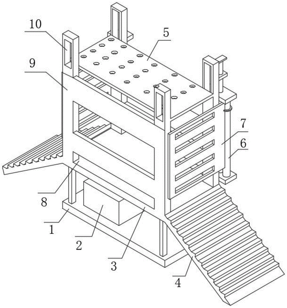
图1为本发明的立体图;Fig. 1 is a perspective view of the present invention;
图2为本发明的围栏的入口关闭、出口打开时的正视图;Fig. 2 is the front view when the entrance of the fence of the present invention is closed and the exit is opened;
图3为图2中A处放大的结构示意图;Fig. 3 is a schematic structural diagram enlarged at place A in Fig. 2;
图4为图2中联动组件的结构示意图;Fig. 4 is a schematic structural diagram of the linkage assembly in Fig. 2;
图5为图2中弹性件的结构示意图;Fig. 5 is a schematic structural view of the elastic member in Fig. 2;
图6为本发明的围栏的入口打开、出口关闭时的正视图;Fig. 6 is the front view when the entrance of the fence of the present invention is opened and the exit is closed;
图7为刮板和螺纹柱一的俯视图。Figure 7 is a top view of the scraper and the threaded column one.
主要符号说明:Description of main symbols:
1、底座;2、采集箱;3、底板;4、踏板;5、顶板;6、转轴一;7、门一;8、固定槽;9、固定框;10、立柱;11、采集管;12、出料管;13、固定罩;14、固定轴;15、刮板;16、螺纹柱一;17、真空泵;18、固定块;19、限位块;20、齿条一;21、齿条二;22、转轴二;23、齿条三;24、棘轮齿;25、棘轮;26、抵接柱;27、活动齿条;28、固定环;29、连接齿轮;30、固定筒;31、传动轴;32、驱逐杆;33、门二;34、螺纹柱二;35、移动块;36、固定齿轮;37、主动齿轮;38、从动齿轮;39、固定板;40、滑套;41、安装槽;42、套杆;43、定位孔;44、连接块;45、滑槽;46、料槽。1. Base; 2. Collection box; 3. Bottom plate; 4. Pedal; 5. Top plate; 6.
具体实施方式detailed description
下面,结合附图以及具体实施方式,对本发明做进一步描述,需要说明的是,在不相冲突的前提下,以下描述的各实施例之间或各技术特征之间可以任意组合形成新的实施例。Below, the present invention will be further described in conjunction with the accompanying drawings and specific implementation methods. It should be noted that, under the premise of not conflicting, the various embodiments described below or the technical features can be combined arbitrarily to form new embodiments. .
实施例1:Example 1:
请结合图1-6,本实施例的一种便于保定羊的羊奶采集设备,包括底座1、安装在底座1顶部的围栏和安装在围栏顶部的顶板5,其特征在于,底座1的顶部安装采集机构,采集机构包括安装在底座1顶部的采集箱2和用于在采集箱2内制造负压环境的真空泵17,真空泵17的吸气管道与采集箱2内部连通,采集箱2上安装有多个采集管11,采集管11的端部安装有吸嘴,采集箱2的一侧底部安装有出料管12,且出料管12上安装有阀门;Please combine Figures 1-6, a kind of goat milk collection equipment that is convenient for Baoding sheep in this embodiment includes a
围栏包括安装在底座1顶部的底板1、固定在底板1顶部的固定框9和两个分别固定在底座1两侧短边上的踏板4,踏板4倾斜设置,且踏板4上表面设置有台阶,踏板的设置方便样进出围栏,固定框9的一侧短边开设有入口,固定框9的另一侧短边开设有出口,固定框9的一侧长边外壁上安装有用于封堵入口的门一7和用于封堵出口的门二33,且门二33内侧壁上安装有料槽46,固定框9的一侧外壁上转动连接有转轴一6、固定轴14和转轴二22,固定轴14外周套接有主动齿轮37,转轴一6的外周套接有与主动齿轮37啮合的从动齿轮38,门一7固定在转轴一6的外周,门二33固定在转轴二22的外周,料槽46的设置可以在里面放置饲料,从而给保证羊在采集的过程中更加的平和,不会有过多的运动。The fence includes a
固定框9的外壁上安装有用于驱动门一7和门二33开合的驱动机构,固定框9外壁上安装有传动件、以用于在门一7开合的时候驱动顶板5升降,驱动机构包括滑接在固定框9外壁上的齿条一20、固定在齿条一20底面的齿条二21、滑接在固定框9外壁上的齿条三23和安装在固定框9外壁上用于驱动齿条三23移动的伸缩件,伸缩件采用电动伸缩杆,固定框9的外壁上安装有PLC控制器,用于控制真空泵17和伸缩件的运行,固定轴14的外周套接有与齿条一20啮合的固定齿轮36,转轴二22的外周套接有与齿条三23啮合的驱动齿轮,齿条一20与齿条三23之间安装有联动组件,通过伸缩件伸长带动齿条三23向靠近门一7的一侧移动,从而逐渐将门二33打开。The outer wall of the fixed
联动组件包括转动连接在固定框9外壁上的连接轴、套接在连接轴外部的联动齿轮和固定在连接轴另一端的棘轮25,联动齿轮与齿条二21啮合,齿条三23顶部安装有多个用于在齿条三23向远离门一7一侧移动时驱动棘轮25转动的棘轮齿24,固定框9外壁上安装有用于卡接齿条一20的定位组件,定位组件包括通过弹性件安装在固定框9外壁上的固定块18、固定在1固定块8顶部的限位块19和固定在固定块18底部的固定环28,固定框9的外壁上开设有竖直设置的安装槽41,弹性件包括沿竖直方向固定在安装槽41内的套杆42、活动套设在套杆42外部的滑套40和活动套设在滑套40外部的弹簧二,弹簧二位于滑套40的底部与安装槽41底部之间,滑套40的一端延伸至安装槽41外部并与固定块18的外壁固接,齿条一20的底面开设有与限位块19吻合的定位孔43,齿条三23的另一端固定有抵接柱26,抵接柱26远离齿条3的一端为直角三角形机构、以用于在与固定环28抵接后在齿条三23向靠近门一7移动的过程中驱动固定环28下移,门二33在打开的过程中,齿条三23向靠近门一7的一侧移动,直到门二33完全打开并固定框9长边一侧外壁平行时,抵接柱26开始与限位环28接触,而同时棘轮齿24也开始与棘轮25接触,从而逐渐将限位框28向下压挤,直到限位块19从定位孔43内部退出来,但此时棘轮25并不会被棘轮齿24拨动,而当门二33关闭的时候,在限位块19未卡合在定位孔43内部的情况下,棘轮齿24跟随齿条三23向远离门一7一侧移动的过程中会驱动棘轮25逆时针转动,进而带动齿条二向远离门二33的一侧移动,齿条一20则是跟随齿条二21同步移动,齿条以20移动后则是可以带动固定齿轮36转动,从而使得固定轴14同步转动,固定轴14转动后则是可以驱动转轴一6转动,从而在齿条一20向靠近门一7移动的过程中可以将门一7逐渐打开,最终达到了逐渐在门二关闭的过程中将门一7打开,直到门一7则完全打开后棘轮齿24与棘轮25脱离接触,之后齿条三23继续向远离门一7的一侧移动,直到门二33完全关闭。The linkage assembly includes a connecting shaft rotatably connected to the outer wall of the fixed
固定框9的顶部四个边角的位置处均固定有立柱10,立柱10表面开设有竖直设置的移动槽,传动件包括固定在固定轴14顶部的螺纹柱二34和四个分别滑接在四个移动槽内的移动块35,其中一个移动块35螺纹套接在螺纹柱二34外部,在固定轴14转动的同时可以带动螺纹柱二34同步转动,当门一打开的同时,螺纹柱二34正转,从而带动移动块35上移,进而将顶板5逐渐抬高,使得羊进入围栏内部后不会被顶板5阻碍到,反之,门一7关闭的时候,则是可以带动螺纹柱34反转,进而之间将顶板5下移,从而给限制羊的活动空间大小。The positions of the top four corners of the fixed
本实施例中的实施原理为:采集羊奶的时候,在门一7打开的情况下,将羊从入口一侧的踏板4上驱赶至围栏内侧,之后再直接用手将门一7关闭即可,而在门一7关闭的同时,齿条一20会向远离门一7的一侧移动,直到门一7完全关闭后,限位块19则与定位孔43对齐,并在弹簧二的作用下卡合在定位孔43内,而转轴一6则是会跟随齿条一20的移动而转动,从而带动固定轴14朝与之相反的方向转动,而这时螺纹柱二34跟随固定轴14同步转动,即螺纹柱二34此时反转,进而在门一7关闭的同时逐渐将压板5下压,从而限制羊的活动空间,避免羊在围栏内部起跳,之后再通过PLC控制器启动真空泵17,然后再将采集管11上的闸阀打开,随之将该采集管11上的吸嘴对准羊的乳房部位进行羊奶采集,而不使用的采集管11上的闸阀则是不打开;The implementation principle in this embodiment is: when collecting goat milk, when the
采集结束后,再通过PLC控制器启动伸缩件伸长,从而带动齿条三23向靠近门一7的一侧移动,进而逐渐将门二33打开,门二完全打开后就可以将围栏内的样从出口处驱赶下去,之后在伸缩件继续的伸长过程中,抵接板26开始与固定环28接触而逐渐进入到固定环28的内圈,固定环28开始顺着抵接板26的斜面下移,此时弹簧二被压缩,直到固定管28的内圈与抵接板26的平面接触后,抵接板26的继续向靠近门一7的一侧移动时才不会压迫固定环28下移,而固定环28在下移的过程中则是带动限位块19退出到定位孔43的外部去,之后在伸缩件收缩的过程中,棘轮齿24则是会先于限位块19卡进定位孔43内部之间带动棘轮25转动,从而使得齿条一20向靠近门一7的一侧移动,从而逐渐将门一7打开,而齿条一20开始移动后,则定位孔43与限位块19之间的相对位置已经发生改变,因此在抵接板26与固定环28脱离接触后,限位块19只会在弹簧二的作用下抵接在齿条一20的底面,直到门一7完全打开后,棘轮齿24开始与棘轮25分离,之后门二33在伸缩件的继续收缩过程汇总继续关闭,直到完全闭合而将出口封堵起来,然后就可以从入口进入。After the acquisition is completed, the extension of the telescopic part is started by the PLC controller, thereby driving the rack three 23 to move to the side close to the door one 7, and then gradually opening the door two 33. After the door two is fully opened, the sample in the enclosure can be moved Drive down from the exit, and then during the continuous elongation of the telescopic element, the
实施例2:Example 2:
结合图2和图6,本实施例在实施例1的基础上,进一步的改进在于:固定框9侧面还安装有用于在门二33打开后驱赶羊的驱赶组件,固定框9的两侧长边外壁上均开设有多个沿且长度方向设置的固定槽8,多个固定槽9从上到下分布,且最下方的固定槽8底部与底板3顶面齐平,驱赶组件包括安装在固定框9长边外壁上的传动轴31、固定在传动轴31外周的驱逐杆32和安装在固定框9外壁上用于驱动传动轴31转动的驱动件,驱逐杆32位于固定框9侧面的一个固定槽8的位置处,从而使得传动轴31转动后,驱逐杆32可以通过固定槽8进入到围栏内侧并对羊群的臀部进行推挤,驱动件包括固定在固定框9外壁上的固定筒30、滑接在固定框9外壁上的活动齿条27和套接在传动轴31外部的连接齿轮29,固定筒30的一侧内壁上固定有弹簧一,活动齿条27位于连接齿轮29远离固定框9外壁的一侧并与连接齿轮29啮合,活动齿条27的一端延伸至固定筒30内与弹簧一的另一端固接,齿条三23的底面固定有用于推动活动齿条27移动的固定板39,在齿条三23向靠近门一7移动的过程中将门二33完全打开的时候,固定板39开始与活动齿条27的一端抵接,从而在齿条三23继续向门一7移动的同时驱动活动齿条27移动。2 and 6, on the basis of
本实施例的实施原理为:在门二33完全打开后之后,固定板39开始与活动齿条27的一端抵接,随着伸缩件的继续伸长,齿条三23继续向靠近门一7的一侧移动,从而带动活动齿条27向靠近门一7的一侧移动,弹簧一随之被压缩,而活动齿条27向靠近门一7的一侧移动的同时会带动传动轴31正转,从而使得驱逐杆32通过固定槽8进入到围栏内侧并对羊群的臀部进行推挤,从而逐渐将羊从出口赶出去。The implementation principle of this embodiment is: after the
实施例3:Example 3:
结合图2、图6和图7本实施例在实施例1和2的基础上,进一步的改进在于:围栏底部安装有用于清理底板3上粪便的清理组件,清理组件包括滑接在底板3顶面的刮板15和用于驱动刮板15沿底板3宽度方向移动的连接件,传动件与传动轴31传动连接、以使刮板15在传动轴31转动的同时移动,刮板15的长度小于底板3的长度,避免刮板15过长而在羊从温岚出口出去的时候踩到刮板15上,连接件包括沿底板3宽度方向固定在底板3顶面的固定罩13、安装在固定罩13内的螺纹柱一16和螺纹连接在螺纹柱一16外部的连接块44,固定罩13的两侧长边外壁上均开设有延其长度方向开设有滑槽45,刮板15的底面开设有与固定罩13外周吻合的凹槽,固定罩13卡合在凹槽内,连接块44的两端分别贯穿两个滑槽45、并与凹槽的两侧固接,螺纹柱一16的一端延伸至固定罩13外部并固定有从动锥齿轮,固定轴14的底部固定有与从动锥齿轮啮合的主动锥齿轮。In conjunction with Fig. 2, Fig. 6 and Fig. 7, on the basis of Embodiments 1 and 2, this embodiment is further improved in that: a cleaning assembly for cleaning feces on the bottom plate 3 is installed at the bottom of the fence, and the cleaning assembly includes a sliding connection on the top of the bottom plate 3 The scraper 15 on the surface and the connecting piece used to drive the scraper 15 to move along the width direction of the bottom plate 3, the transmission piece is connected with the drive shaft 31 so that the scraper 15 moves while the drive shaft 31 rotates, the length of the scraper 15 Less than the length of the base plate 3, to avoid the scraper 15 being too long and stepping on the scraper 15 when the sheep goes out from the Wenlan exit, the connector includes a fixed cover 13 fixed on the top surface of the base plate 3 along the width direction of the base plate 3, installed on the The threaded column one 16 in the fixed cover 13 and the connection block 44 that is threadedly connected outside the threaded column one 16, the both sides long side outer walls of the fixed cover 13 are provided with a chute 45 along its length direction, and the scraper 15 The bottom surface is provided with a groove that coincides with the periphery of the fixed cover 13, the fixed cover 13 is engaged in the groove, the two ends of the connecting block 44 respectively pass through two slide grooves 45, and are affixed to both sides of the groove, and the threaded column one One end of 16 extends to the outside of the fixed cover 13 and is fixed with a driven bevel gear, and the bottom of the fixed shaft 14 is fixed with a driving bevel gear meshed with the driven bevel gear.
本实施例的实施原理为:在传动轴31带动驱逐杆32向围栏内侧转动的过程中,传动轴31也带动螺纹柱一16正转,从而使得连接块44向远离从动锥齿轮的一侧移动,进而带动刮板15向远离从动锥齿轮的一侧移动,从而将底板3顶面的粪便刮下并从底板3的一侧掉落下去,反之,在传动轴41重新往回转的过程中,则是会带动螺纹柱一16反转,直到将刮板15重新移动回底板3边云靠近从动锥齿轮的一侧位置处。The implementation principle of this embodiment is: when the
上述实施方式仅为本发明的优选实施方式,不能以此来限定本发明保护的范围,本领域的技术人员在本发明的基础上所做的任何非实质性的变化及替换均属于本发明所要求保护的范围。The above-mentioned embodiment is only a preferred embodiment of the present invention, and cannot be used to limit the protection scope of the present invention. Any insubstantial changes and substitutions made by those skilled in the art on the basis of the present invention belong to the scope of the present invention. Scope of protection claimed.
Claims (8)
Priority Applications (1)
| Application Number | Priority Date | Filing Date | Title |
|---|---|---|---|
| CN202211325357.8A CN115500268B (en) | 2022-10-27 | 2022-10-27 | A goat milk collection device convenient for protecting goats |
Applications Claiming Priority (1)
| Application Number | Priority Date | Filing Date | Title |
|---|---|---|---|
| CN202211325357.8A CN115500268B (en) | 2022-10-27 | 2022-10-27 | A goat milk collection device convenient for protecting goats |
Publications (2)
| Publication Number | Publication Date |
|---|---|
| CN115500268A true CN115500268A (en) | 2022-12-23 |
| CN115500268B CN115500268B (en) | 2025-04-11 |
Family
ID=84512274
Family Applications (1)
| Application Number | Title | Priority Date | Filing Date |
|---|---|---|---|
| CN202211325357.8A Active CN115500268B (en) | 2022-10-27 | 2022-10-27 | A goat milk collection device convenient for protecting goats |
Country Status (1)
| Country | Link |
|---|---|
| CN (1) | CN115500268B (en) |
Cited By (2)
| Publication number | Priority date | Publication date | Assignee | Title |
|---|---|---|---|---|
| CN118696841A (en) * | 2024-07-25 | 2024-09-27 | 新疆畜牧科学院 | A goat milking parlor |
| CN119969298A (en) * | 2025-02-26 | 2025-05-13 | 安徽农业大学 | Boar hoof trimming equipment |
Citations (3)
| Publication number | Priority date | Publication date | Assignee | Title |
|---|---|---|---|---|
| US20090078206A1 (en) * | 2006-03-16 | 2009-03-26 | Nihon University | Automatic milking apparatus for laboratory animals |
| CN107980645A (en) * | 2017-11-29 | 2018-05-04 | 颍上县国源农场 | A kind of pig house that can be cleaned automatically |
| CN110326538A (en) * | 2019-07-17 | 2019-10-15 | 李久峰 | A kind of the automatic scraping excrement flusher and its operation method of the operation of band pig |
-
2022
- 2022-10-27 CN CN202211325357.8A patent/CN115500268B/en active Active
Patent Citations (3)
| Publication number | Priority date | Publication date | Assignee | Title |
|---|---|---|---|---|
| US20090078206A1 (en) * | 2006-03-16 | 2009-03-26 | Nihon University | Automatic milking apparatus for laboratory animals |
| CN107980645A (en) * | 2017-11-29 | 2018-05-04 | 颍上县国源农场 | A kind of pig house that can be cleaned automatically |
| CN110326538A (en) * | 2019-07-17 | 2019-10-15 | 李久峰 | A kind of the automatic scraping excrement flusher and its operation method of the operation of band pig |
Cited By (2)
| Publication number | Priority date | Publication date | Assignee | Title |
|---|---|---|---|---|
| CN118696841A (en) * | 2024-07-25 | 2024-09-27 | 新疆畜牧科学院 | A goat milking parlor |
| CN119969298A (en) * | 2025-02-26 | 2025-05-13 | 安徽农业大学 | Boar hoof trimming equipment |
Also Published As
| Publication number | Publication date |
|---|---|
| CN115500268B (en) | 2025-04-11 |
Similar Documents
| Publication | Publication Date | Title |
|---|---|---|
| CN216405312U (en) | Trash rack cleaning equipment for hydraulic engineering | |
| CN106912454A (en) | A kind of silkworm cultivates special rearing instrument integrated equipment for wastewater treatment | |
| CN115500268B (en) | A goat milk collection device convenient for protecting goats | |
| CN209773742U (en) | Laser cutting machine | |
| CN207549556U (en) | A kind of Chinese medicine slag squeezer | |
| CN210754575U (en) | Stamping die processing waste material processing apparatus | |
| CN113006025A (en) | Hydraulic engineering is with suspension rubbish cleaning device | |
| CN111287484A (en) | A kind of deep hole planting reinforcement device for reinforced concrete structure | |
| CN209482282U (en) | A kind of collection device of water conservancy river floating refuse | |
| CN210412185U (en) | Hardware stamping die adding and waste absorbing machine | |
| CN221045582U (en) | Medicine residue filtering structure for plaster processing | |
| CN219723789U (en) | Ash removal device for hollow brick processing | |
| CN109106540B (en) | A urinal for automatic disposal of excrement | |
| CN115814483B (en) | Vinasse processing apparatus after white spirit raw materials fermentation | |
| CN215339198U (en) | Concrete compression testing machine convenient to it is clean | |
| CN214654641U (en) | A device for collecting and processing coke water flushing at the tail of a coke blocking vehicle | |
| CN214982189U (en) | Wetting device lays bricks | |
| CN209530311U (en) | A kind of municipal sewage treatment tapping equipment | |
| CN223555587U (en) | Solid-liquid separation type sewage lifter | |
| CN220901343U (en) | Animal doctor laboratory waste treatment equipment | |
| CN222299570U (en) | Daily chemical article sample detection device | |
| CN114439668B (en) | Trash rack for water turbine | |
| CN218486660U (en) | Pseudo-ginseng belt cleaning device | |
| CN220414429U (en) | Water collecting structure for hydraulic and hydroelectric engineering | |
| CN223738573U (en) | Rotary grid trash remover of hydropower station |
Legal Events
| Date | Code | Title | Description |
|---|---|---|---|
| PB01 | Publication | ||
| PB01 | Publication | ||
| SE01 | Entry into force of request for substantive examination | ||
| SE01 | Entry into force of request for substantive examination | ||
| GR01 | Patent grant | ||
| GR01 | Patent grant |