CN115489737A - Agricultural plant protection is with monitoring unmanned aerial vehicle equipment that sprays insecticide - Google Patents
Agricultural plant protection is with monitoring unmanned aerial vehicle equipment that sprays insecticide Download PDFInfo
- Publication number
- CN115489737A CN115489737A CN202211381532.5A CN202211381532A CN115489737A CN 115489737 A CN115489737 A CN 115489737A CN 202211381532 A CN202211381532 A CN 202211381532A CN 115489737 A CN115489737 A CN 115489737A
- Authority
- CN
- China
- Prior art keywords
- pesticide
- unmanned aerial
- aerial vehicle
- fixedly connected
- spraying
- Prior art date
- Legal status (The legal status is an assumption and is not a legal conclusion. Google has not performed a legal analysis and makes no representation as to the accuracy of the status listed.)
- Granted
Links
- 238000012544 monitoring process Methods 0.000 title claims abstract description 43
- 239000007921 spray Substances 0.000 title claims abstract description 37
- 239000002917 insecticide Substances 0.000 title claims description 6
- 239000000575 pesticide Substances 0.000 claims abstract description 138
- 238000005507 spraying Methods 0.000 claims abstract description 67
- 238000007599 discharging Methods 0.000 claims abstract description 35
- 239000003814 drug Substances 0.000 claims description 50
- 230000001105 regulatory effect Effects 0.000 claims description 13
- 229920000742 Cotton Polymers 0.000 claims description 9
- 241000883990 Flabellum Species 0.000 claims description 2
- 230000000694 effects Effects 0.000 abstract description 4
- XLYOFNOQVPJJNP-UHFFFAOYSA-N water Chemical compound O XLYOFNOQVPJJNP-UHFFFAOYSA-N 0.000 description 8
- 238000010586 diagram Methods 0.000 description 7
- 239000007788 liquid Substances 0.000 description 4
- 239000003595 mist Substances 0.000 description 3
- 230000001681 protective effect Effects 0.000 description 3
- 230000033001 locomotion Effects 0.000 description 2
- 238000004519 manufacturing process Methods 0.000 description 2
- 239000000779 smoke Substances 0.000 description 2
- 206010017533 Fungal infection Diseases 0.000 description 1
- 208000031888 Mycoses Diseases 0.000 description 1
- 241000607479 Yersinia pestis Species 0.000 description 1
- 238000010521 absorption reaction Methods 0.000 description 1
- 238000000889 atomisation Methods 0.000 description 1
- 230000009286 beneficial effect Effects 0.000 description 1
- 238000003384 imaging method Methods 0.000 description 1
- 230000002262 irrigation Effects 0.000 description 1
- 238000003973 irrigation Methods 0.000 description 1
- 239000000203 mixture Substances 0.000 description 1
- 239000010914 pesticide waste Substances 0.000 description 1
- 239000002689 soil Substances 0.000 description 1
- 238000001429 visible spectrum Methods 0.000 description 1
- 239000002699 waste material Substances 0.000 description 1
Images




Classifications
-
- B—PERFORMING OPERATIONS; TRANSPORTING
- B64—AIRCRAFT; AVIATION; COSMONAUTICS
- B64D—EQUIPMENT FOR FITTING IN OR TO AIRCRAFT; FLIGHT SUITS; PARACHUTES; ARRANGEMENT OR MOUNTING OF POWER PLANTS OR PROPULSION TRANSMISSIONS IN AIRCRAFT
- B64D1/00—Dropping, ejecting, releasing or receiving articles, liquids, or the like, in flight
- B64D1/16—Dropping or releasing powdered, liquid, or gaseous matter, e.g. for fire-fighting
- B64D1/18—Dropping or releasing powdered, liquid, or gaseous matter, e.g. for fire-fighting by spraying, e.g. insecticides
-
- A—HUMAN NECESSITIES
- A01—AGRICULTURE; FORESTRY; ANIMAL HUSBANDRY; HUNTING; TRAPPING; FISHING
- A01M—CATCHING, TRAPPING OR SCARING OF ANIMALS; APPARATUS FOR THE DESTRUCTION OF NOXIOUS ANIMALS OR NOXIOUS PLANTS
- A01M7/00—Special adaptations or arrangements of liquid-spraying apparatus for purposes covered by this subclass
- A01M7/005—Special arrangements or adaptations of the spraying or distributing parts, e.g. adaptations or mounting of the spray booms, mounting of the nozzles, protection shields
- A01M7/0064—Protection shields
- A01M7/0067—Protection shields with recovering of liquids
-
- A—HUMAN NECESSITIES
- A01—AGRICULTURE; FORESTRY; ANIMAL HUSBANDRY; HUNTING; TRAPPING; FISHING
- A01M—CATCHING, TRAPPING OR SCARING OF ANIMALS; APPARATUS FOR THE DESTRUCTION OF NOXIOUS ANIMALS OR NOXIOUS PLANTS
- A01M7/00—Special adaptations or arrangements of liquid-spraying apparatus for purposes covered by this subclass
- A01M7/0089—Regulating or controlling systems
- A01M7/0096—Testing of spray-patterns
-
- B—PERFORMING OPERATIONS; TRANSPORTING
- B64—AIRCRAFT; AVIATION; COSMONAUTICS
- B64C—AEROPLANES; HELICOPTERS
- B64C27/00—Rotorcraft; Rotors peculiar thereto
- B64C27/04—Helicopters
- B64C27/08—Helicopters with two or more rotors
-
- B—PERFORMING OPERATIONS; TRANSPORTING
- B64—AIRCRAFT; AVIATION; COSMONAUTICS
- B64C—AEROPLANES; HELICOPTERS
- B64C39/00—Aircraft not otherwise provided for
- B64C39/02—Aircraft not otherwise provided for characterised by special use
- B64C39/024—Aircraft not otherwise provided for characterised by special use of the remote controlled vehicle type, i.e. RPV
Landscapes
- Life Sciences & Earth Sciences (AREA)
- Engineering & Computer Science (AREA)
- Pest Control & Pesticides (AREA)
- Insects & Arthropods (AREA)
- Wood Science & Technology (AREA)
- Zoology (AREA)
- Environmental Sciences (AREA)
- Aviation & Aerospace Engineering (AREA)
- Mechanical Engineering (AREA)
- Catching Or Destruction (AREA)
Abstract
The invention discloses a pesticide spraying monitoring unmanned aerial vehicle device for agricultural plant protection, which relates to the technical field of plant protection unmanned aerial vehicles and comprises the following components: a body; a pesticide spraying mechanism; a resistance change mechanism; an adjustment mechanism; a steering mechanism; a monitoring mechanism; when the flying speed of the unmanned aerial vehicle is increased from a normal speed, the resistance changing mechanism can work under the action of wind resistance generated by the flying of the unmanned aerial vehicle, so that the adjusting mechanism is driven to change the pesticide discharging amount of the pesticide discharging pipe in the pesticide spraying mechanism, the adjusting mechanism can drive the steering mechanism to rotate while the pesticide discharging amount is changed, the direction of the spray head rotates towards the flying direction of the unmanned aerial vehicle, the spray head sprays pesticide towards the flying direction of the unmanned aerial vehicle while the pesticide spraying amount is increased when the speed of the unmanned aerial vehicle is increased, sprayed pesticide droplets become large in size and large in mass, the direction of the sprayed pesticide droplets is forward, the drift amount generated by the flying speed of the unmanned aerial vehicle is reduced, the pesticide is enabled to have more effects on crops, and the pesticide loss is reduced.
Description
Technical Field
The invention relates to the technical field of plant protection unmanned aerial vehicles, in particular to pesticide spraying monitoring unmanned aerial vehicle equipment for agricultural plant protection.
Background
Plant protection unmanned aerial vehicle is an unmanned aircraft who is applied to the agricultural, and the purpose helps improving crops output and monitoring crops growth. Its sensors and digital imaging capabilities can help farmers become more aware of their fields and help to improve crop yield and farm efficiency. Plant protection unmanned aerial vehicle lets peasants see their field from the sky. Such aerial views may reveal a number of problems such as irrigation, soil changes, pest and fungal infections, and the like. The captured multispectral image can display a near infrared view and a visible spectrum view, so that the difference between healthy plants and unhealthy plants is shown to farmers, and the difference cannot be clearly seen by naked eyes at ordinary times. Thus, these views can be used to help assess the growth and yield of crops.
At present, plant protection unmanned aerial vehicle is when carrying out the pesticide and sprays, the drift volume that its pesticide sprayed the production receives unmanned aerial vehicle flight speed's influence, unmanned aerial vehicle flight speed is faster, the drift of production is more, when unmanned aerial vehicle flies the spraying operation according to regular speed, the drift volume that the pesticide produced is less, when unmanned aerial vehicle flight speed increases, the drift volume increase that the pesticide that sprays produced this moment, and then cause the waste of pesticide, for this reason we propose an agricultural plant protection with the monitoring unmanned aerial vehicle equipment of spraying pesticide to solve above-mentioned problem.
Disclosure of Invention
The invention aims to solve the problems that in the prior art, when pesticide is sprayed, the drift amount generated by pesticide spraying is influenced by the flight speed of an unmanned aerial vehicle, the faster the flight speed of the unmanned aerial vehicle is, the more drift is generated, when the unmanned aerial vehicle carries out flight spraying operation at a specified speed, the drift amount generated by pesticide is smaller, and when the flight speed of the unmanned aerial vehicle is increased, the drift amount generated by the sprayed pesticide is increased, but when the existing plant protection unmanned aerial vehicle carries out pesticide spraying, the corresponding change of the drift amount of the pesticide according to the flight speed cannot be realized, so that pesticide waste is caused, and the invention provides the monitoring unmanned aerial vehicle equipment for spraying pesticide for agricultural plant protection.
In order to achieve the purpose, the invention adopts the following technical scheme:
the utility model provides an agricultural plant protection is with monitoring unmanned aerial vehicle equipment of spraying insecticide, includes:
the novel spraying machine comprises a machine body, wherein a rotor wing is installed at the top of the machine body, support frames are fixedly connected to two sides of the outer side wall of the machine body, a medicine spraying mechanism is fixedly connected to the middle position of the bottom of the machine body, a fixed sleeve is fixedly connected to the bottom of the medicine spraying mechanism, a protective cover is fixedly connected to the middle position of the bottom of the fixed sleeve, absorbent cotton is fixedly connected to the periphery of the bottom of the fixed sleeve, and an air inlet pipe is fixedly connected to the position, located on the absorbent cotton, of the fixed sleeve;
the resistance change mechanism is mounted at the top of the pesticide spraying mechanism and is driven by wind resistance generated by flight of the unmanned aerial vehicle;
the adjusting mechanism is driven by the resistance changing mechanism and is used for adjusting the medicine output amount of the medicine spraying mechanism;
the steering mechanism is arranged at the bottom of the pesticide spraying mechanism and is driven by the adjusting mechanism;
and the monitoring mechanism is arranged inside the fixed sleeve.
Preferably, the pesticide spraying mechanism comprises a pesticide box, a pesticide feeding pipe, a pesticide discharging pipe and a pesticide discharging box; the both sides of medical kit and the opposite direction end connection who adds the pencil, the one end of arranging the pencil and the lateral wall fixed connection of medical kit, the one end that the medical kit was kept away from to the pencil and the top fixed connection who arranges the medicine box, the inside wall bottom middle part position fixed connection of medical kit has the guide plate.
Preferably, the resistance changing mechanism comprises a wind resistance plate, a rotating shaft, a fixing plate and a gear; the top of the wind resistance plate is fixedly connected with the outer side wall of the rotating shaft, the outer side wall of the rotating shaft is rotatably connected with the fixed plate, and the inner side wall of the gear is fixedly connected with the middle position of the outer side wall of the rotating shaft.
Preferably, the adjusting mechanism comprises an adjusting plate, a rack, an adjusting hole, a connecting block, a return spring and a connecting rod; the top of regulating plate and the bottom fixed connection of rack, the top at the regulating plate is seted up to the regulation hole, the end in opposite directions of connecting block and the lateral wall both sides fixed connection of regulating plate, reset spring's one end and the lateral wall fixed connection of connecting block, the top of connecting rod and the bottom fixed connection of regulating plate.
Preferably, the steering mechanism comprises a fixed rod, a rotating rod and a spray head; the bottom of the fixed rod is fixedly connected with the top of the spray head, and the outer side wall of the rotating rod is fixedly connected with the fixed rod.
Preferably, the monitoring mechanism comprises a double-shaft motor, a speed reducing motor, a connecting shaft, a camera and fan blades; the one end and the gear motor fixed connection of biax motor, gear motor's one end fixed connection is kept away from with biax motor to the connecting axle, gear motor keeps away from biax motor's one end and the fixed connection of connecting axle, the bottom fixedly connected with camera of connecting axle, the lateral wall fixedly connected with flabellum of connecting axle, the top of connecting axle is rotated and is connected with the mount, the lateral wall of mount and the inside wall fixed connection of fixed cover, biax motor's lateral wall and the inside wall fixed connection of fixed cover.
Preferably, the top of the medicine box is fixedly connected with the bottom of the machine body, and the bottom of the medicine box is fixedly connected with the top of the fixing sleeve.
Preferably, the bottom of the fixed plate is fixedly connected with the top of the medicine discharging box, and the wind resistance plates are symmetrically arranged along the middle part of the rotating shaft.
Preferably, the top of regulating plate is laminated with the interior lateral wall top of arranging the medicine box mutually, the regulating plate run through one side of arranging the medicine box and with arrange medicine box sliding connection, the top of rack meshes with the outside lateral wall of gear mutually, reset spring keeps away from the one end of connecting block and arranges the inside wall fixed connection of medicine box, the size of regulation hole is the same with the size of arranging the pencil.
Preferably, the outer side wall of the rotating rod is attached to the outer side wall of the connecting rod and slides mutually, and the top end of the spray head is rotatably connected with the inner part of the bottom side wall of the medicine discharging box.
Compared with the prior art, the invention has the beneficial effects that:
1. according to the invention, through the arrangement of the resistance change mechanism, when the flying speed of the unmanned aerial vehicle is increased from a normal speed, the resistance change mechanism can work under the action of wind resistance generated by the flying of the unmanned aerial vehicle, and further drive the adjusting mechanism to change the pesticide discharging amount of the pesticide discharging pipe in the pesticide spraying mechanism, and the adjusting mechanism can drive the steering mechanism to rotate while changing the pesticide discharging amount, so that the direction of the spray head rotates towards the flying direction of the unmanned aerial vehicle, and therefore, when the speed of the unmanned aerial vehicle is increased, the spray head sprays pesticide towards the flying direction of the unmanned aerial vehicle while the pesticide spraying amount is increased, the sprayed pesticide fog drops become larger in size and larger in quality, and the direction is forward, so that the drift amount generated by the flying speed of the unmanned aerial vehicle during pesticide spraying is reduced, more pesticide acts on crops, and the loss of pesticide is reduced.
2. By using the monitoring mechanism, when the unmanned aerial vehicle sprays pesticides, the monitoring mechanism can carry out all-around monitoring, pesticide water vapor generated by pesticide spraying enters the fixed sleeve after being absorbed by the absorbent cotton during monitoring, the double-shaft motor, the speed reduction motor and the camera in the fixed sleeve are cooled, so that the gas is heated, the heated gas forms vortex to blow the pesticides in the pesticide box under the action of the guide plate, the pesticides in the pesticide box are mixed more uniformly, and the heated gas further promotes the movement of pesticide molecules in the pesticide box, so that the uniformity of the pesticides in the pesticide box is promoted.
Drawings
Fig. 1 is a schematic three-dimensional structure diagram of a monitoring unmanned aerial vehicle device for agricultural plant protection pesticide spraying provided by the invention;
fig. 2 is a schematic diagram of a three-dimensional bottom structure of a pesticide spraying monitoring unmanned aerial vehicle device for agricultural plant protection provided by the invention;
fig. 3 is a schematic view of a three-dimensional middle cut-away structure of a pesticide spraying monitoring unmanned aerial vehicle device for agricultural plant protection provided by the invention;
fig. 4 is an enlarged schematic structural diagram of a part a in fig. 3 of the monitoring unmanned aerial vehicle device for agricultural plant protection pesticide spraying provided by the invention;
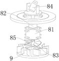
fig. 5 is a schematic three-dimensional structure diagram of a monitoring mechanism of a pesticide spraying monitoring unmanned aerial vehicle device for agricultural plant protection, provided by the invention;
fig. 6 is a schematic diagram of a three-dimensional bottom structure of a monitoring mechanism of a pesticide spraying monitoring unmanned aerial vehicle device for agricultural plant protection, provided by the invention;
fig. 7 is a schematic three-dimensional structure diagram of a resistance change mechanism and an adjusting mechanism of a pesticide spraying monitoring unmanned aerial vehicle device for agricultural plant protection, which is provided by the invention;
fig. 8 is a schematic three-dimensional structure diagram of a resistance change mechanism, an adjusting mechanism and a steering mechanism of the agricultural plant protection pesticide spraying monitoring unmanned aerial vehicle device provided by the invention.
In the figure: 1. a body; 2. a rotor; 3. a support frame; 4. a pesticide spraying mechanism; 41. a medicine chest; 42. a medicine feeding pipe; 43. a medicine discharge pipe; 44. arranging the medicine box; 5. a resistance change mechanism; 51. a wind resistance plate; 52. a rotating shaft; 53. a fixing plate; 54. a gear; 6. an adjustment mechanism; 61. an adjusting plate; 62. a rack; 63. an adjustment hole; 64. connecting blocks; 65. a return spring; 66. a connecting rod; 7. a steering mechanism; 71. a fixing rod; 72. a rotating rod; 73. a spray head; 8. a monitoring mechanism; 81. a double-shaft motor; 82. a reduction motor; 83. a connecting shaft; 84. a camera; 85. a fan blade; 9. a baffle; 10. absorbent cotton; 11. an air inlet pipe; 12. a protective cover; 13. and (4) fixing sleeves.
Detailed Description
The technical solutions in the embodiments of the present invention will be clearly and completely described below with reference to the drawings in the embodiments of the present invention, and it is obvious that the described embodiments are only a part of the embodiments of the present invention, and not all of the embodiments.
Referring to fig. 1-8, an agricultural plant protection is with monitoring unmanned aerial vehicle equipment of spraying insecticide includes:
the novel water-absorbing type aircraft comprises an aircraft body 1, wherein a rotor wing 2 is installed at the top of the aircraft body 1, support frames 3 are fixedly connected to two sides of the outer side wall of the aircraft body 1, a medicine spraying mechanism 4 is fixedly connected to the middle position of the bottom of the aircraft body 1, a fixed sleeve 13 is fixedly connected to the bottom of the medicine spraying mechanism 4, a protective cover 12 is fixedly connected to the middle position of the bottom of the fixed sleeve 13, water-absorbing cotton 10 is fixedly connected to the periphery of the bottom of the fixed sleeve 13, and an air inlet pipe 11 is fixedly connected to the part, located on the water-absorbing cotton 10, of the fixed sleeve 13;
the resistance changing mechanism 5 is installed at the top of the pesticide spraying mechanism 4, and the resistance changing mechanism 5 is driven by wind resistance generated by flying of the unmanned aerial vehicle;
the adjusting mechanism 6 is driven by the resistance changing mechanism 5, and the adjusting mechanism 6 is used for adjusting the pesticide discharging amount of the pesticide spraying mechanism 4;
the steering mechanism 7, the steering mechanism 7 is installed on the bottom of the pesticide spraying mechanism 4, the steering mechanism 7 is driven by the regulating mechanism 6;
the monitoring mechanism 8, the monitoring mechanism 8 is installed inside the fixed sleeve 13;
through the setting of above-mentioned structure, the pesticide water smoke that produces when having realized carrying out the pesticide to unmanned aerial vehicle and spraying carries out effectual absorption, the surface that has reduced water smoke and act on safety cover 12 causes the condition emergence probability of shooting unsharpness, unmanned aerial vehicle speed has still been realized when increasing, make shower nozzle 73 spray to unmanned aerial vehicle flight direction when the medicine yield increases, make the pesticide droplet grow big quality that sprays, the direction is forward, thereby it sprays the drift volume that receives the unmanned aerial vehicle flight speed to produce to have reduced the pesticide, make on more effects of pesticide and crops, the loss of pesticide has been reduced.
Wherein, the pesticide spraying mechanism 4 comprises a pesticide box 41, a pesticide feeding pipe 42, a pesticide discharging pipe 43 and a pesticide discharging box 44; the two sides of the medicine box 41 are fixedly connected with the opposite ends of the medicine feeding pipe 42, one end of the medicine discharging pipe 43 is fixedly connected with the outer side wall of the medicine box 41, one end, far away from the medicine box 41, of the medicine discharging pipe 43 is fixedly connected with the top of the medicine discharging box 44, the middle part of the bottom of the inner side wall of the medicine box 41 is fixedly connected with the flow guide plate 9, and the inner side wall of the medicine discharging pipe 43 is provided with a micro water pump of which the model is CQ69-QC3700-8145;
through the arrangement of the structure, the pesticide can be effectively transmitted, and the efficiency and the quality of pesticide spraying are ensured.
The resistance changing mechanism 5 comprises a wind resistance plate 51, a rotating shaft 52, a fixing plate 53 and a gear 54; the top of the wind resistance plate 51 is fixedly connected with the outer side wall of the rotating shaft 52, the outer side wall of the rotating shaft 52 is rotatably connected with the fixed plate 53, and the inner side wall of the gear 54 is fixedly connected with the middle position of the outer side wall of the rotating shaft 52;
through the arrangement of the structure, the different deviation degrees of the wind resistance plate 51 are realized according to the different flight speeds of the unmanned aerial vehicle, and power is provided for the work of the subsequent adjusting mechanism 6 and the steering mechanism 7.
The adjusting mechanism 6 comprises an adjusting plate 61, a rack 62, an adjusting hole 63, a connecting block 64, a return spring 65 and a connecting rod 66; the top of the adjusting plate 61 is fixedly connected with the bottom of the rack 62, the adjusting hole 63 is formed in the top of the adjusting plate 61, the opposite ends of the connecting blocks 64 are fixedly connected with the two sides of the outer side wall of the adjusting plate 61, one end of the return spring 65 is fixedly connected with the outer side wall of the connecting block 64, and the top of the connecting rod 66 is fixedly connected with the bottom of the adjusting plate 61;
through the setting of above-mentioned structure, realized changing the row's dosage of arranging pencil 43 according to the windage that unmanned aerial vehicle flight produced to make the volume that shower nozzle 73 sprayed increase, the effectual drift volume that has reduced the spraying pesticide.
Wherein, the steering mechanism 7 comprises a fixed rod 71, a rotating rod 72 and a spray head 73; the bottom of the fixed rod 71 is fixedly connected with the top of the spray head 73, and the outer side wall of the rotating rod 72 is fixedly connected with the fixed rod 71;
through the arrangement of the structure, the spraying direction of the spray head 73 is changed according to the change of the wind resistance, and the drift amount of the sprayed pesticide is further reduced.
Wherein, the monitoring mechanism 8 comprises a double-shaft motor 81, a speed reducing motor 82, a connecting shaft 83, a camera 84 and fan blades 85; one end of a double-shaft motor 81 is fixedly connected with a speed reducing motor 82, a connecting shaft 83 is fixedly connected with one end of the double-shaft motor 81 far away from the speed reducing motor 82, one end of the speed reducing motor 82 far away from the double-shaft motor 81 is fixedly connected with the connecting shaft 83, the bottom of the connecting shaft 83 is fixedly connected with a camera 84, the outer side wall of the connecting shaft 83 is fixedly connected with fan blades 85, the top of the connecting shaft 83 is rotatably connected with a fixed frame, the outer side wall of the fixed frame is fixedly connected with the inner side wall of the fixed sleeve 13, and the outer side wall of the double-shaft motor 81 is fixedly connected with the inner side wall of the fixed sleeve 13;
in addition, the model number of the biaxial motor 81 is 86HS80B46014; the model of the speed reducing motor 82 is ZWBPDO06006; the model number of camera 84 is BCC2000Plus;
through the setting of above-mentioned structure, realized reducing the temperature to biax motor 81, gear motor 82 and camera 84 in fixed cover 13 for gaseous intensification, the gaseous of intensification will form the swirl under the effect of guide plate 9 and blow the pesticide in the medical kit 41, makes the pesticide in the medical kit 41 mix more evenly, and the gaseous velocity of motion that will further promote the interior pesticide molecule of medical kit 41 of intensification, thereby has promoted the homogeneity of pesticide in the medical kit 41.
Wherein, the top of the medicine box 41 is fixedly connected with the bottom of the machine body 1, and the bottom of the medicine box 41 is fixedly connected with the top of the fixed sleeve 13.
Wherein, the bottom of the fixed plate 53 is fixedly connected with the top of the medicine discharging box 44, and the windage plates 51 are symmetrically arranged along the middle part of the rotating shaft 52.
Wherein, the top of regulating plate 61 is laminated with the inside wall top of arranging medicine box 44 mutually, regulating plate 61 runs through one side of arranging medicine box 44 and with arrange medicine box 44 sliding connection, the top of rack 62 and the outside of gear 54 are mutually meshed, the one end that reset spring 65 kept away from connecting block 64 and the inside wall fixed connection of arranging medicine box 44, the size of regulation hole 63 is the same with the size of arranging medicine pipe 43.
Wherein, the outer side wall of the rotating rod 72 is attached to the outer side wall of the connecting rod 66 and slides mutually, the top end of the spray head 73 is rotatably connected with the inner part of the bottom side wall of the medicine discharging box 44, and the rotating rod 72 is attracted with the connecting rod 66;
through the arrangement of the structure, the connecting rod 66 can drive the fixing rod 71 and the spray head 73 to rotate through the rotating rod 72, so that the spray head 73 is adjusted in angle.
When the pesticide box is used, firstly, enough pesticide is added into the pesticide box 41 through the pesticide adding pipe 42, then the machine body 1 can be controlled to fly to a farmland under the action of the rotor wing 2 and fly at a specified speed, and at the moment, the micro water pump, the double-shaft motor 81, the speed reducing motor 82 and the camera 84 can be started;
the pesticide in the pesticide box 41 is pumped into the pesticide discharging box 44 through the pesticide discharging pipe 43 by the operation of the micro water pump, and then is sprayed on crops in a farmland through the spray head 73;
the connecting shaft 83 is driven to rotate by the operation of the double-shaft motor 81, so that the fan blades 85 start to rotate, pesticide mist generated by spraying from the outside is extracted, the pesticide mist can pass through the absorbent cotton 10 to absorb pesticide and water in the water mist, outside air enters the fixed sleeve 13 through the air inlet pipe 11 to absorb heat generated by the operation of the camera 84, the double-shaft motor 81 and the speed reduction motor 82, the absorbed gas can enter the medicine box 41 under the action of the guide plate 9 to enable the liquid medicine in the medicine box 41 to form a vortex, the mixing of the liquid medicine in the medicine box 41 is promoted, and the heat is absorbed by the gas, so that the heat of the gas can act on the liquid medicine in the medicine box 41 to promote the moving speed of molecules in the liquid medicine, the mixing efficiency and the quality of the pesticide are further promoted, and meanwhile, after the double-shaft motor 81 is decelerated by the speed reduction motor 82, the bottom camera 84 is driven by the connecting shaft 83 to rotate and shoot, and a shooting picture is transmitted to a control terminal of a controller;
when the flying speed of the unmanned aerial vehicle is increased, the wind resistance generated by the flying of the corresponding unmanned aerial vehicle is increased, at the moment, the wind resistance plate 51 blows the wind resistance plate 51 to rotate along the rotating shaft 52 towards the wind flowing direction under the action of the wind resistance, so that the rotating shaft 52 is driven to rotate, the rotating shaft 52 drives the gear 54 fixed on the outer surface of the rotating shaft to rotate, at the moment, the gear 54 drives the rack 62 meshed with the gear to move towards the opposite flying direction, so that the adjusting plate 61 is driven to move, the overlapped part of the adjusting hole 63 and the pesticide discharging pipe 43 is increased, the pesticide amount entering the pesticide discharging box 44 through the pesticide discharging pipe 43 is increased, at the moment, the connecting block 64 moves outwards to stretch the reset spring 65, and the adjusting plate 61 moves to drive the rotating rod 72 to slide downwards along the connecting rod 66 and move downwards through the connecting rod 66, so that the rotating rod 72 drives the spray head 73 to rotate towards the flying direction through the fixing rod 71, and the spraying direction of the spray head 73 is changed due to change of the wind resistance, so that the spraying direction is drifted, and the situation in the opposite direction can be initially reduced;
meanwhile, the amount of the pesticide entering the pesticide discharging box 44 is increased, so that the amount of the pesticide sprayed by the spray head 73 is increased, and the overlapped part of the adjusting hole 63 and the pesticide discharging pipe 43 is increased, so that the internal pressure of the pesticide discharging box 44 is reduced, the pressure of the pesticide sprayed by the spray head 73 is reduced, the atomization effect of the pesticide formed under the action of the pressure is reduced, the size and the weight of the fog drops sprayed by the spray head 73 are increased, coarse fog drops are formed, the acting force of wind force on the fog drops is reduced to a certain extent, and the drift amount of the sprayed pesticide is further reduced;
in addition, when the flight speed of the unmanned aerial vehicle increases, the flight distance of the unmanned aerial vehicle in corresponding time increases, and the relative drift amount generated by the pesticide spraying amount affected by the flight speed of the unmanned aerial vehicle increases, so that the pesticide spraying amount needs to be changed according to the flight speed of the unmanned aerial vehicle, and the angle of the spray head 73 is adjusted, so that the pesticide spraying direction of the spray head 73 faces the flight direction of the unmanned aerial vehicle, the pesticide action and the area of crops are increased to a certain extent, and the pesticide sprayed by the spray head 73 is coarse fog drops by adjusting the pesticide spraying amount according to the flight speed of the unmanned aerial vehicle, the influence of wind resistance on the sprayed pesticide is further reduced, and the drift amount generated by the pesticide affected by the flight speed of the unmanned aerial vehicle is reduced;
when the flight speed of the unmanned aerial vehicle is recovered, the connecting block 64 automatically recovers under the action of the return spring 65, and then the adjusting plate 61 is driven to recover the initial position, so that the rack 62 drives the rotating shaft 52 to rotate through the gear 54, and thus the wind resistance plate 51 is driven to recover the initial position, and meanwhile the connecting rod 66 moves through the rotating rod 72, the rotating rod 72 slides upwards on the side wall of the connecting rod 66, and then the fixing rod 71 drives the spray head 73 to recover the initial position;
after the pesticide is sprayed, the machine body 1 can be controlled to fly back.
In the description of the present invention, it is to be understood that the terms "center", "longitudinal", "lateral", "length", "width", "thickness", "upper", "lower", "front", "rear", "left", "right", "vertical", "horizontal", "top", "bottom", "inner", "outer", "clockwise", "counterclockwise", and the like, indicate orientations and positional relationships based on those shown in the drawings, and are used only for convenience of description and simplicity of description, and do not indicate or imply that the equipment or element being referred to must have a particular orientation, be constructed and operated in a particular orientation, and thus, should not be considered as limiting the present invention.
Furthermore, the terms "first", "second" and "first" are used for descriptive purposes only and are not to be construed as indicating or implying relative importance or implicitly indicating the number of technical features indicated. Thus, a feature defined as "first" or "second" may explicitly or implicitly include one or more of that feature. In the description of the present invention, "a plurality" means two or more unless specifically defined otherwise.
The above description is only for the preferred embodiment of the present invention, but the scope of the present invention is not limited thereto, and any person skilled in the art should be considered as the technical solutions and the inventive concepts of the present invention within the technical scope of the present invention.
Claims (10)
1. The utility model provides an agricultural plant protection is with monitoring unmanned aerial vehicle equipment of spraying insecticide which characterized in that includes:
the novel spraying machine comprises a machine body (1), wherein a rotor (2) is installed at the top of the machine body (1), support frames (3) are fixedly connected to two sides of the outer side wall of the machine body (1), a spraying mechanism (4) is fixedly connected to the middle of the bottom of the machine body (1), a fixing sleeve (13) is fixedly connected to the bottom of the spraying mechanism (4), a protecting cover (12) is fixedly connected to the middle of the bottom of the fixing sleeve (13), absorbent cotton (10) is fixedly connected to the periphery of the bottom of the fixing sleeve (13), and an air inlet pipe (11) is fixedly connected to the part, located on the absorbent cotton (10), of the fixing sleeve (13);
the resistance changing mechanism (5) is installed at the top of the pesticide spraying mechanism (4), and the resistance changing mechanism (5) is driven by wind resistance generated by flight of the unmanned aerial vehicle;
the adjusting mechanism (6) is driven by the resistance changing mechanism (5), and the adjusting mechanism (6) is used for adjusting the medicine output amount of the medicine spraying mechanism (4);
the steering mechanism (7) is installed at the bottom of the pesticide spraying mechanism (4), and the steering mechanism (7) is driven by the adjusting mechanism (6);
monitoring mechanism (8), monitoring mechanism (8) are installed the inside of fixed cover (13).
2. The agricultural plant protection pesticide spraying monitoring unmanned aerial vehicle device as claimed in claim 1, wherein the pesticide spraying mechanism (4) comprises a pesticide box (41), a pesticide feeding pipe (42), a pesticide discharging pipe (43) and a pesticide discharging box (44); the both sides of medical kit (41) and the opposite direction end fixed connection who adds pencil (42), the one end of row pencil (43) and the lateral wall fixed connection of medical kit (41), the top fixed connection of the one end of medical kit (41) and row medicine box (44) is kept away from in row pencil (43), inside wall bottom middle part position fixed connection of medical kit (41) has guide plate (9).
3. The agricultural plant protection pesticide-spraying monitoring unmanned aerial vehicle device as claimed in claim 1, wherein the resistance change mechanism (5) comprises a wind resistance plate (51), a rotating shaft (52), a fixing plate (53) and a gear (54); the top of the wind resistance plate (51) is fixedly connected with the outer side wall of the rotating shaft (52), the outer side wall of the rotating shaft (52) is rotatably connected with the fixed plate (53), and the inner side wall of the gear (54) is fixedly connected with the middle position of the outer side wall of the rotating shaft (52).
4. The agricultural plant protection pesticide-spraying monitoring unmanned aerial vehicle device as claimed in claim 1, wherein the adjusting mechanism (6) comprises an adjusting plate (61), a rack (62), an adjusting hole (63), a connecting block (64), a return spring (65) and a connecting rod (66); the top of regulating plate (61) and the bottom fixed connection of rack (62), the top at regulating plate (61) is seted up in regulation hole (63), the lateral wall both sides fixed connection of the end in opposite directions and regulating plate (61) of connecting block (64), the one end of reset spring (65) and the lateral wall fixed connection of connecting block (64), the top of connecting rod (66) and the bottom fixed connection of regulating plate (61).
5. The agricultural plant protection pesticide-spraying monitoring unmanned aerial vehicle device as claimed in claim 1, wherein the steering mechanism (7) comprises a fixed rod (71), a rotating rod (72) and a spray head (73); the bottom of the fixed rod (71) is fixedly connected with the top of the spray head (73), and the outer side wall of the rotating rod (72) is fixedly connected with the fixed rod (71).
6. The agricultural plant protection pesticide spraying monitoring unmanned aerial vehicle device as claimed in claim 1, wherein the monitoring mechanism (8) comprises a double-shaft motor (81), a speed reducing motor (82), a connecting shaft (83), a camera (84) and fan blades (85); the one end and gear motor (82) fixed connection of biax motor (81), the one end fixed connection of gear motor (82) is kept away from with biax motor (81) in connecting axle (83), the fixed connection of one end and connecting axle (83) of biax motor (81) is kept away from in gear motor (82), the bottom fixedly connected with camera (84) of connecting axle (83), the lateral wall fixedly connected with flabellum (85) of connecting axle (83), the top of connecting axle (83) is rotated and is connected with the mount, the lateral wall of mount and the inside wall fixed connection of fixed cover (13), the lateral wall of biax motor (81) and the inside wall fixed connection of fixed cover (13).
7. The agricultural plant protection pesticide spraying monitoring unmanned aerial vehicle device as claimed in claim 2, wherein the top of the pesticide box (41) is fixedly connected with the bottom of the machine body (1), and the bottom of the pesticide box (41) is fixedly connected with the top of the fixing sleeve (13).
8. The agricultural plant protection is with monitoring unmanned aerial vehicle equipment of spraying insecticide of claim 3, characterized in that, the bottom of fixed plate (53) and the top fixed connection of arranging the medicine box (44), choke plate (51) is the symmetry setting along the middle part of pivot (52).
9. The agricultural plant protection pesticide spraying monitoring unmanned aerial vehicle device as claimed in claim 4, wherein the top of the adjusting plate (61) is attached to the top of the inner side wall of the pesticide discharging box (44), the adjusting plate (61) penetrates through one side of the pesticide discharging box (44) and is in sliding connection with the pesticide discharging box (44), the top of the rack (62) is meshed with the outer side wall of the gear (54), one end, far away from the connecting block (64), of the return spring (65) is fixedly connected with the inner side wall of the pesticide discharging box (44), and the size of the adjusting hole (63) is the same as that of the pesticide discharging pipe (43).
10. The agricultural plant protection pesticide-spraying monitoring unmanned aerial vehicle device as claimed in claim 5, wherein the outer side wall of the rotating rod (72) is attached to the outer side wall of the connecting rod (66) and slides with each other, and the top end of the spray head (73) is rotatably connected with the inside of the bottom side wall of the pesticide discharging box (44).
Priority Applications (1)
| Application Number | Priority Date | Filing Date | Title |
|---|---|---|---|
| CN202211381532.5A CN115489737B (en) | 2022-11-04 | 2022-11-04 | Agricultural plant protection is with monitoring unmanned aerial vehicle equipment that sprays insecticide |
Applications Claiming Priority (1)
| Application Number | Priority Date | Filing Date | Title |
|---|---|---|---|
| CN202211381532.5A CN115489737B (en) | 2022-11-04 | 2022-11-04 | Agricultural plant protection is with monitoring unmanned aerial vehicle equipment that sprays insecticide |
Publications (2)
| Publication Number | Publication Date |
|---|---|
| CN115489737A true CN115489737A (en) | 2022-12-20 |
| CN115489737B CN115489737B (en) | 2023-12-19 |
Family
ID=85115912
Family Applications (1)
| Application Number | Title | Priority Date | Filing Date |
|---|---|---|---|
| CN202211381532.5A Active CN115489737B (en) | 2022-11-04 | 2022-11-04 | Agricultural plant protection is with monitoring unmanned aerial vehicle equipment that sprays insecticide |
Country Status (1)
| Country | Link |
|---|---|
| CN (1) | CN115489737B (en) |
Cited By (6)
| Publication number | Priority date | Publication date | Assignee | Title |
|---|---|---|---|---|
| CN116552789A (en) * | 2023-05-30 | 2023-08-08 | 嘉兴安行信息科技有限公司 | Unmanned aerial vehicle large-traffic intelligent sprinkler system |
| CN117598272A (en) * | 2023-11-28 | 2024-02-27 | 黑龙江惠达科技股份有限公司 | A method for adjusting and controlling the distance between centrifugal nozzles of agricultural unmanned aerial vehicles |
| CN117885897A (en) * | 2023-01-10 | 2024-04-16 | 徐州沣收喷灌设备有限公司 | A drone for sprinkler irrigation |
| CN118419265A (en) * | 2024-04-20 | 2024-08-02 | 浙江天拓航空科技有限公司 | A drone for spraying pesticides for agriculture |
| CN118850329A (en) * | 2024-09-25 | 2024-10-29 | 闽清县久润农业发展有限公司 | Agricultural plant protection drone |
| CN120642818A (en) * | 2025-08-06 | 2025-09-16 | 浙江亨坤科技有限公司 | Agricultural production unmanned aerial vehicle is with spilling medicine device |
Citations (6)
| Publication number | Priority date | Publication date | Assignee | Title |
|---|---|---|---|---|
| JPH10337145A (en) * | 1997-06-09 | 1998-12-22 | Yamaha Motor Co Ltd | Drug spraying system |
| CN105905302A (en) * | 2016-06-02 | 2016-08-31 | 中国农业大学 | Intelligent pesticide applying system and control method of plant protection unmanned aerial vehicle |
| CN208624436U (en) * | 2018-06-14 | 2019-03-22 | 华南农业大学 | A kind of agricultural plant protection unmanned plane sprinkling system compensated automatically with droplet drift detection |
| CN211167411U (en) * | 2019-10-24 | 2020-08-04 | 南京国器智能装备有限公司 | A real-time anti-drift system for drone spraying |
| CN111557292A (en) * | 2020-05-18 | 2020-08-21 | 尹跃洋 | Pesticide spraying aircraft that windward sprayed |
| US20200329690A1 (en) * | 2017-11-21 | 2020-10-22 | Basf Agro Trademarks Gmbh | Unmanned aerial vehicle |
-
2022
- 2022-11-04 CN CN202211381532.5A patent/CN115489737B/en active Active
Patent Citations (6)
| Publication number | Priority date | Publication date | Assignee | Title |
|---|---|---|---|---|
| JPH10337145A (en) * | 1997-06-09 | 1998-12-22 | Yamaha Motor Co Ltd | Drug spraying system |
| CN105905302A (en) * | 2016-06-02 | 2016-08-31 | 中国农业大学 | Intelligent pesticide applying system and control method of plant protection unmanned aerial vehicle |
| US20200329690A1 (en) * | 2017-11-21 | 2020-10-22 | Basf Agro Trademarks Gmbh | Unmanned aerial vehicle |
| CN208624436U (en) * | 2018-06-14 | 2019-03-22 | 华南农业大学 | A kind of agricultural plant protection unmanned plane sprinkling system compensated automatically with droplet drift detection |
| CN211167411U (en) * | 2019-10-24 | 2020-08-04 | 南京国器智能装备有限公司 | A real-time anti-drift system for drone spraying |
| CN111557292A (en) * | 2020-05-18 | 2020-08-21 | 尹跃洋 | Pesticide spraying aircraft that windward sprayed |
Cited By (7)
| Publication number | Priority date | Publication date | Assignee | Title |
|---|---|---|---|---|
| CN117885897A (en) * | 2023-01-10 | 2024-04-16 | 徐州沣收喷灌设备有限公司 | A drone for sprinkler irrigation |
| CN116552789A (en) * | 2023-05-30 | 2023-08-08 | 嘉兴安行信息科技有限公司 | Unmanned aerial vehicle large-traffic intelligent sprinkler system |
| CN117598272A (en) * | 2023-11-28 | 2024-02-27 | 黑龙江惠达科技股份有限公司 | A method for adjusting and controlling the distance between centrifugal nozzles of agricultural unmanned aerial vehicles |
| CN118419265A (en) * | 2024-04-20 | 2024-08-02 | 浙江天拓航空科技有限公司 | A drone for spraying pesticides for agriculture |
| CN118850329A (en) * | 2024-09-25 | 2024-10-29 | 闽清县久润农业发展有限公司 | Agricultural plant protection drone |
| CN118850329B (en) * | 2024-09-25 | 2025-02-28 | 闽清县久润农业发展有限公司 | Agricultural plant protection drone |
| CN120642818A (en) * | 2025-08-06 | 2025-09-16 | 浙江亨坤科技有限公司 | Agricultural production unmanned aerial vehicle is with spilling medicine device |
Also Published As
| Publication number | Publication date |
|---|---|
| CN115489737B (en) | 2023-12-19 |
Similar Documents
| Publication | Publication Date | Title |
|---|---|---|
| CN115489737B (en) | Agricultural plant protection is with monitoring unmanned aerial vehicle equipment that sprays insecticide | |
| CN110217397B (en) | An anti-floating spraying mechanism for plant protection drones | |
| CN113631480A (en) | Rack of multi-rotor unmanned aerial vehicle, agricultural plant protection unmanned aerial vehicle and control method | |
| CN107128493B (en) | Wide-width plant protection unmanned aerial vehicle with multiple transverse rotors and driving method | |
| CN109526913A (en) | A kind of sprinkling for agricultural production accurately intelligent plant protection drone | |
| US11919642B2 (en) | Large-load unmanned aerial vehicle for plant protection with adjustable spraying swath and pesticide application amount | |
| CN109625277A (en) | A kind of divergence expression medicine liquid spray frame structure of agricultural spray unmanned plane | |
| CN205221114U (en) | Unmanned aerial vehicle sprays scope adjusting device and unmanned aerial vehicle thereof | |
| CN105253303A (en) | Device and method for regulating unmanned aerial vehicle spray range | |
| CN211391696U (en) | An air curtain spray anti-drift device for plant protection drones | |
| CN109533340A (en) | A kind of unmanned plane flusher of Auto-matching dose | |
| CN111713473A (en) | Agricultural plant protection unmanned aerial vehicle of high-efficient operation | |
| CN116552789A (en) | Unmanned aerial vehicle large-traffic intelligent sprinkler system | |
| CN111907710B (en) | Sugarcane medicament spraying system | |
| CN120517595B (en) | A pesticide spraying drone | |
| CN210479038U (en) | An anti-drift spraying mechanism for plant protection unmanned aircraft | |
| CN207658067U (en) | A kind of plant protection drone vision auxiliary sighting system | |
| CN115349507A (en) | Unmanned aerial vehicle is with targeting atomizer and unmanned aerial vehicle | |
| CN207225662U (en) | A kind of wide cut plant protection unmanned plane of the more rotors of cross-arranging type | |
| CN219108567U (en) | Pesticide sprays plant protection machine | |
| CN118419265B (en) | A drone for spraying pesticides for agriculture | |
| CN104401492A (en) | Seeding device | |
| CN119705897A (en) | Intelligent plant protection unmanned aerial vehicle spraying droplet deposition path monitoring device | |
| CN111301684A (en) | A sprinkler for plant protection unmanned aerial vehicle | |
| CN216581035U (en) | Air-assisted pesticide spraying device based on unmanned aerial vehicle |
Legal Events
| Date | Code | Title | Description |
|---|---|---|---|
| PB01 | Publication | ||
| PB01 | Publication | ||
| SE01 | Entry into force of request for substantive examination | ||
| SE01 | Entry into force of request for substantive examination | ||
| GR01 | Patent grant | ||
| GR01 | Patent grant |