CN115489400A - Seat hook installation structure and body structure - Google Patents
Seat hook installation structure and body structure Download PDFInfo
- Publication number
- CN115489400A CN115489400A CN202211180525.9A CN202211180525A CN115489400A CN 115489400 A CN115489400 A CN 115489400A CN 202211180525 A CN202211180525 A CN 202211180525A CN 115489400 A CN115489400 A CN 115489400A
- Authority
- CN
- China
- Prior art keywords
- mounting
- latch hook
- pillar
- main body
- seat
- Prior art date
- Legal status (The legal status is an assumption and is not a legal conclusion. Google has not performed a legal analysis and makes no representation as to the accuracy of the status listed.)
- Granted
Links
Images


Classifications
-
- B—PERFORMING OPERATIONS; TRANSPORTING
- B60—VEHICLES IN GENERAL
- B60N—SEATS SPECIALLY ADAPTED FOR VEHICLES; VEHICLE PASSENGER ACCOMMODATION NOT OTHERWISE PROVIDED FOR
- B60N2/00—Seats specially adapted for vehicles; Arrangement or mounting of seats in vehicles
- B60N2/005—Arrangement or mounting of seats in vehicles, e.g. dismountable auxiliary seats
-
- B—PERFORMING OPERATIONS; TRANSPORTING
- B60—VEHICLES IN GENERAL
- B60N—SEATS SPECIALLY ADAPTED FOR VEHICLES; VEHICLE PASSENGER ACCOMMODATION NOT OTHERWISE PROVIDED FOR
- B60N2/00—Seats specially adapted for vehicles; Arrangement or mounting of seats in vehicles
- B60N2/90—Details or parts not otherwise provided for
- B60N2/919—Positioning and locking mechanisms
- B60N2002/924—Positioning and locking mechanisms using electric or hydraulic energy
-
- B—PERFORMING OPERATIONS; TRANSPORTING
- B60—VEHICLES IN GENERAL
- B60N—SEATS SPECIALLY ADAPTED FOR VEHICLES; VEHICLE PASSENGER ACCOMMODATION NOT OTHERWISE PROVIDED FOR
- B60N2/00—Seats specially adapted for vehicles; Arrangement or mounting of seats in vehicles
- B60N2/90—Details or parts not otherwise provided for
- B60N2/919—Positioning and locking mechanisms
- B60N2002/952—Positioning and locking mechanisms characterised by details of the locking system
Landscapes
- Engineering & Computer Science (AREA)
- Aviation & Aerospace Engineering (AREA)
- Transportation (AREA)
- Mechanical Engineering (AREA)
- Body Structure For Vehicles (AREA)
Abstract
本申请提供一种座椅锁钩安装结构及车身结构。座椅锁钩安装结构包括锁钩组件及锁钩安装支架,锁钩安装支架包括主体部与若干自主体部的周侧弯折延伸的安装部,主体部上设有锁钩定位部,若干安装部包括轮罩内板安装部、C环安装部、角窗下横梁安装部及C柱安装部。锁钩安装支架设有多个安装部,分别与车身侧围连接,增强了车身侧围的强度,可改善车身NTF水平。
The present application provides a seat lock hook installation structure and a vehicle body structure. The seat lock hook installation structure includes a lock hook assembly and a lock hook installation bracket. The lock hook installation bracket includes a main body and several installation parts that are bent and extended from the peripheral side of the main body. The main body is provided with a lock hook positioning part. The parts include the installation part of the inner panel of the wheel house, the installation part of the C ring, the installation part of the lower beam of the corner window and the installation part of the C pillar. The locking hook mounting bracket is provided with multiple mounting parts, which are respectively connected to the side wall of the body, which enhances the strength of the side wall of the body and can improve the NTF level of the body.
Description
技术领域technical field
本申请涉及汽车技术领域,尤其涉及一种座椅锁钩安装结构及车身结构。The present application relates to the technical field of automobiles, in particular to a seat lock hook installation structure and a vehicle body structure.
背景技术Background technique
随着经济水平的提高,汽车保有量的不断增加,消费者对汽车性能的需求也越来越高。汽车内部的降噪能力已成为人们选择汽车的主要因素之一。NVH(车辆振动、噪声及声振粗糙度)性能由于能够直接被消费者所感知,可以说NVH性能的优劣直接影响了消费者对产品的品质印象。车身作为结构噪声及振动的末端传递路径,无论是由动力总成激励引起的NVH问题,亦或是由路面激励引起的NVH问题,都会经过车身传递至人耳。目前车企采用平台化开发,动力总成及底盘悬架系统基本都是借用的,所以整车NVH性能逐步的依赖优化车身系统的NTF(振动-噪声传递函数)和VTF(振动-振动传递函数)来改善整车NVH问题。With the improvement of the economic level and the continuous increase of car ownership, consumers' demand for car performance is also getting higher and higher. The noise reduction ability of the car interior has become one of the main factors when people choose a car. NVH (Vehicle Vibration, Noise, and Harshness) performance can be directly perceived by consumers. It can be said that the quality of NVH performance directly affects consumers' impression of product quality. As the end transmission path of structural noise and vibration, the car body, whether the NVH problem caused by the powertrain excitation or the NVH problem caused by the road surface excitation, will be transmitted to the human ear through the car body. At present, car companies adopt platform-based development, and the powertrain and chassis suspension systems are basically borrowed. Therefore, the NVH performance of the vehicle gradually depends on optimizing the NTF (vibration-noise transfer function) and VTF (vibration-vibration transfer function) of the body system. ) to improve the vehicle NVH problem.
在相关技术中,车身NTF的优化,主要与车身的结构设计有关,工程师们最常用的手段即控制车身某些关键区域的结构刚度,或者车身大板件的模态分布,来优化关注的NTF频段问题。而在现有技术中,支撑架通过加强板与后轮内鼓包和后轮外鼓包实现高强度焊接,仅加强了后轮钣金的强度,对位于后轮内鼓包及后轮外鼓包上部最薄弱的侧围部分的加强作用有限,车身 NTF的改善程度低。In related technologies, the optimization of the NTF of the car body is mainly related to the structural design of the car body. The most common means used by engineers is to control the structural stiffness of certain key areas of the car body, or the modal distribution of large body panels to optimize the NTF of concern. Band problem. However, in the prior art, the support frame achieves high-strength welding with the rear wheel inner bulge and the rear wheel outer bulge through the reinforcement plate, which only strengthens the strength of the rear wheel sheet metal, and is located at the uppermost part of the rear wheel inner bulge and the rear wheel outer bulge. The weak side wall part has limited reinforcement effect, and the degree of improvement of body NTF is low.
因此,有必要提供一种改进的座椅锁钩安装结构以解决上述问题。Therefore, it is necessary to provide an improved seat hook installation structure to solve the above problems.
发明内容Contents of the invention
本申请提供一种加强车身侧围强度及优化车身NTF的座椅锁钩安装结构及车身结构。The present application provides a seat lock hook installation structure and a vehicle body structure for strengthening the side wall strength of the vehicle body and optimizing the NTF of the vehicle body.
本申请公开了一种座椅锁钩安装结构,包括锁钩组件及锁钩安装支架,所述锁钩安装支架包括主体部及若干自主体部的周侧弯折延伸的安装部,所述主体部上设有锁钩定位部,所述若干安装部包括轮罩内板安装部、C环安装部、角窗下横梁安装部及C柱安装部。The present application discloses a seat lock hook installation structure, which includes a lock hook assembly and a lock hook installation bracket. The lock hook installation bracket includes a main body and several installation parts bent and extended from the periphery of the main body. A lock hook positioning part is provided on the upper part, and the several installation parts include a wheel house inner panel installation part, a C ring installation part, a corner window lower beam installation part and a C pillar installation part.
进一步地,所述C柱安装部包括第一C柱安装部及第二C柱安装部,所述第一C柱安装部与所述第二C柱安装部连接。Further, the C-pillar installation part includes a first C-pillar installation part and a second C-pillar installation part, and the first C-pillar installation part is connected to the second C-pillar installation part.
进一步地,所述第一C柱安装部及所述第二C柱安装部之间设有第一加强筋,所述C环安装部设有第二加强筋,所述第二加强筋自所述主体部延伸至所述C环安装部。Further, a first reinforcement rib is provided between the first C-pillar installation part and the second C-pillar installation part, and a second reinforcement rib is provided at the C-ring installation part, and the second reinforcement rib is formed from the The main body portion extends to the C-ring mounting portion.
进一步地,所述锁钩安装支架包括自所述主体部延伸的电机固定部,所述电机固定部邻近所述角窗下横梁安装部,且向背离所述角窗下横梁安装部的方向延伸。Further, the lock hook installation bracket includes a motor fixing part extending from the main body, the motor fixing part is adjacent to the corner window lower cross beam installation part, and extends in a direction away from the quarter window lower cross beam installation part .
进一步地,所述主体部包括与所述C柱安装部并列设置的加强部,所述加强部位于所述锁钩定位部的一侧且两端延伸至所述主体部的上、下边缘。Further, the main body part includes a reinforcement part arranged in parallel with the C-pillar installation part, the reinforcement part is located on one side of the locking hook positioning part and both ends extend to the upper and lower edges of the main body part.
进一步地,所述锁钩组件包括安装板及设置在所述安装板上的锁钩,所述安装板通过定位销与所述锁钩定位部配合,所述安装板的上部设有锁止槽。Further, the locking hook assembly includes a mounting plate and a locking hook arranged on the mounting plate, the mounting plate cooperates with the positioning part of the locking hook through a positioning pin, and the upper part of the mounting plate is provided with a locking groove .
进一步地,还包括电机组件,所述电机组件包括电机安装支架、安装在所述电机安装支架上的电机及锁止插销,所述电机驱动所述锁止插销运动。Further, a motor assembly is also included, the motor assembly includes a motor mounting bracket, a motor installed on the motor mounting bracket, and a locking pin, and the motor drives the locking pin to move.
进一步地,所述锁止插销的后端设有限位柱,所述锁止插销的前端设有限位环,所述锁止插销与所述锁止槽配合。Further, the rear end of the locking bolt is provided with a limiting column, and the front end of the locking bolt is provided with a limiting ring, and the locking bolt is matched with the locking groove.
本申请公开了一种车身结构,包括角窗下横梁、C柱、轮罩内板、C环螺栓、后排座椅以及如上所述的座椅锁钩安装结构。The application discloses a vehicle body structure, which includes a corner window lower beam, a C-pillar, a wheel house inner panel, a C-ring bolt, rear seats and the above-mentioned seat lock hook installation structure.
进一步地,所述主体部覆盖所述角窗下横梁、所述C柱、所述轮罩内板及所述C环螺栓的交界区域,所述锁钩组件(10)的一端与所述主体部(21)配合,另一端与所述后排座椅配合。Further, the main body part covers the junction area of the corner window lower beam, the C-pillar, the inner panel of the wheel house and the C-ring bolt, and one end of the locking hook assembly (10) is connected to the main body Part (21) cooperates, and the other end cooperates with described rear seat.
与现有技术相比,本申请的有益效果为锁钩安装支架设有多个安装部,分别与车身侧围连接,增加了车身侧围的强度,同时锁钩组件连接后排座椅,使得后排座椅与车身侧围间接连接,再次增加车身侧围的强度,改善车身NTF水平。Compared with the prior art, the beneficial effect of the present application is that the lock hook mounting bracket is provided with a plurality of mounting parts, which are respectively connected with the side wall of the vehicle body, thereby increasing the strength of the side wall of the vehicle body, and at the same time, the lock hook assembly is connected with the rear seats, so that The rear seats are indirectly connected to the side wall of the body, which again increases the strength of the side wall of the body and improves the NTF level of the body.
应当理解的是,以上的一般描述和后文的细节描述仅是示例性和解释性的,并不能限制本说明书。It is to be understood that both the foregoing general description and the following detailed description are exemplary and explanatory only and are not restrictive of the specification.
附图说明Description of drawings
此处的附图被并入说明书中并构成本说明书的一部分,示出了符合本说明书的实施例,并与说明书一起用于解释本说明书的原理。The accompanying drawings, which are incorporated in and constitute a part of this specification, illustrate embodiments consistent with the specification and together with the description serve to explain the principles of the specification.
图1是座椅锁钩安装结构安装在车身侧围的立体图。Fig. 1 is a perspective view of the seat lock hook installation structure installed on the side wall of the vehicle body.
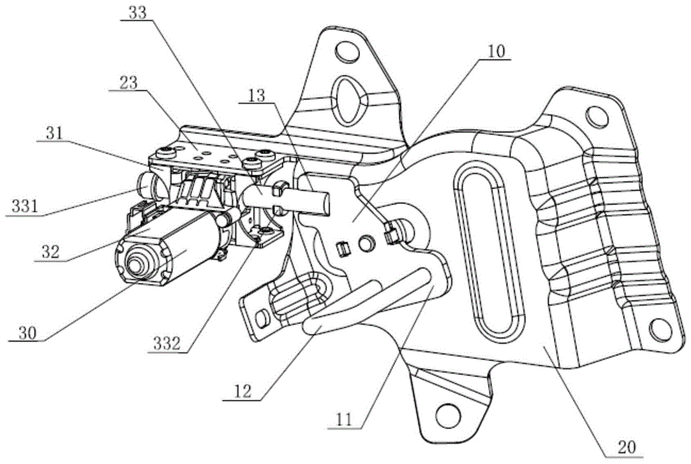
图2是图1中座椅锁钩安装结构的立体图。Fig. 2 is a perspective view of the installation structure of the seat lock hook in Fig. 1 .
图3是图2中锁钩组件的立体图。Fig. 3 is a perspective view of the locking hook assembly in Fig. 2 .
图4是图2中座椅锁钩安装结构另一视角的立体图。Fig. 4 is a perspective view of another viewing angle of the seat lock hook installation structure in Fig. 2 .
图5是图2中锁钩安装支架的立体图。Fig. 5 is a perspective view of the locking hook mounting bracket in Fig. 2 .
图6是应用本发明之前及之后关于原点频响的分析图。Fig. 6 is an analysis graph about the frequency response of the origin before and after applying the present invention.
图7是应用本发明之前及之后关于整车路躁的分析图。Fig. 7 is an analysis diagram about road noise of the whole vehicle before and after applying the present invention.
附图标号说明:锁钩组件、10;安装板、11;锁钩、12;锁止槽、13;锁钩安装支架、20;主体部、21;锁钩定位部、211;加强边、2110;加强部、 212;安装部、22;轮罩内板安装部、221;C环安装部、222;角窗下横梁安装部、223;第一C柱安装部、224;第二C柱安装部、225;第一加强筋、226;第二加强筋、227;电机组件、30;电机安装支架、31;电机、32;锁止插销、 33;限位柱、331;限位环、332;角窗下横梁、40;C柱、50;轮罩内板、60; C环螺栓、70。Description of reference numerals: locking hook assembly, 10; mounting plate, 11; locking hook, 12; locking groove, 13; locking hook mounting bracket, 20; main body, 21; ; Reinforcement part, 212; Installation part, 22; Wheelhouse inner panel installation part, 221; C ring installation part, 222; Corner window lower beam installation part, 223; First C-pillar installation part, 224; Department, 225; first rib, 226; second rib, 227; motor assembly, 30; motor mounting bracket, 31; motor, 32; ; Corner window lower beam, 40; C-pillar, 50; wheel house inner panel, 60; C ring bolts, 70.
具体实施方式detailed description
这里将详细地对示例性实施例进行说明,其示例表示在附图中。下面的描述涉及附图时,除非另有表示,不同附图中的相同数字表示相同或相似的要素。以下示例性实施例中所描述的实施方式并不代表与本说明书相一致的所有实施方式。相反,它们仅是与如所附权利要求书中所详述的、本说明书的一些方面相一致的装置和方法的例子。Reference will now be made in detail to the exemplary embodiments, examples of which are illustrated in the accompanying drawings. When the following description refers to the accompanying drawings, the same numerals in different drawings refer to the same or similar elements unless otherwise indicated. The implementations described in the following exemplary examples do not represent all implementations consistent with this specification. Rather, they are merely examples of apparatuses and methods consistent with aspects of the present specification as recited in the appended claims.
在本说明书使用的术语是仅仅出于描述特定实施例的目的,而非旨在限制本说明书。在本说明书和所附权利要求书中所使用的单数形式的“一种”、“所述”和“该”也旨在包括多数形式,除非上下文清楚地表示其他含义。还应当理解,本文中使用的术语“和/或”是指并包含一个或多个相关联的列出项目的任何或所有可能组合。The terms used in this specification are for the purpose of describing particular embodiments only, and are not intended to limit the specification. As used in this specification and the appended claims, the singular forms "a", "the", and "the" are intended to include the plural forms as well, unless the context clearly dictates otherwise. It should also be understood that the term "and/or" as used herein refers to and includes any and all possible combinations of one or more of the associated listed items.
应当理解,尽管在本说明书可能采用术语第一、第二、第三等来描述各种信息,但这些信息不应限于这些术语。这些术语仅用来将同一类型的信息彼此区分开。例如,在不脱离本说明书范围的情况下,第一信息也可以被称为第二信息,类似地,第二信息也可以被称为第一信息。取决于语境,如在此所使用的词语“如果”可以被解释成为“在……时”或“当……时”或“响应于确定”。It should be understood that although the terms first, second, third, etc. may be used in this specification to describe various information, the information should not be limited to these terms. These terms are only used to distinguish information of the same type from one another. For example, without departing from the scope of this specification, first information may also be called second information, and similarly, second information may also be called first information. Depending on the context, the word "if" as used herein may be interpreted as "at" or "when" or "in response to a determination."
接下来对本说明书实施例进行详细说明。Next, the embodiments of this specification will be described in detail.
如图1所示,本发明座椅锁钩安装结构包括锁钩组件10、用于固定锁钩组件10的锁钩安装支架20及与锁钩组件10配合的电机组件30。车身结构包括座椅锁钩安装结构、角窗下横梁40、C柱50、轮罩内板60、C环螺栓 70及后排座椅。As shown in FIG. 1 , the seat hook installation structure of the present invention includes a
轮罩内板60设在角窗下横梁40的下部,轮罩内板60及角窗下横梁40 分别与C柱50连接。座椅锁钩安装结构分别与角窗下横梁40、C柱50、轮罩内板60及C环螺栓70连接固定,后排座椅通过座椅锁钩安装结构与角窗下横梁40、C柱50、轮罩内板60及C环螺栓70形成的车身侧围连接。The wheel house
如图2至图3所示,锁钩组件10包括安装板11及设置在安装板11上的锁钩12。安装板11与锁钩安装支架20配合,安装板11的上部设有锁止槽 13,安装板11的下部设有安装孔。安装板11通过安装孔与锁钩12过盈配合,锁钩12与后排座椅配合。As shown in FIGS. 2 to 3 , the
如图4至图5所示,锁钩安装支架20包括主体部21、若干自主体部21的周侧弯折延伸的安装部22及电机固定部23。主体部21覆盖角窗下横梁40、C 柱50、轮罩内板60及C环螺栓70的交界区域。As shown in FIGS. 4 to 5 , the locking
主体部21上设有锁钩定位部211及自主体部21的表面凸出的加强部212。锁钩定位部211为条形槽,在主体部21上倾斜设置。锁钩定位部211的边缘部分设有加强边2110,加强边2110的表面高于主体部21。The
锁钩定位部211的一端靠近加强部212,另一端延伸至主体部21的边缘。锁钩定位部211与安装板11通过定位销配合,使得安装板11可沿着锁钩定位部211移动以及通过定位销进行旋转。One end of the locking
加强部212竖直设置并位于锁钩定位部211的一侧。加强部212两端延伸至主体部21的上、下边缘,加强部212的表面高于主体部21的表面。The
安装部22包括轮罩内板安装部221、C环安装部222、角窗下横梁安装部223及C柱安装部。C柱安装部包括第一C柱安装部224及第二C柱安装部225。The mounting
轮罩内板安装部221自主体部21的下侧中部弯折延伸,与轮罩内板60 固定连接,且覆盖轮罩内板60部分区域。C环安装部222自主体部21的一侧弯折延伸,与C环螺栓70固定连接,且覆盖C环螺栓70部分区域。C环安装部222设有第二加强筋227,第二加强筋227自主体部21延伸至C环安装部222。The wheel house inner
角窗下横梁安装部223自主体部21的上侧弯折延伸,与角窗下横梁40 固定连接,且覆盖角窗下横梁40部分区域。C柱安装部自主体部21的另一侧弯折延伸,与C柱50固定连接,且覆盖C柱50部分区域。The corner window lower
第一C柱安装部224与第二C柱安装部225相连接,与加强部212并列设置。第一C柱安装部224及第二C柱安装部225之间设有两个第一加强筋226,第一加强筋226自主体部21延伸至C柱安装部的边缘。The first C-
电机固定部23自主体部21的边缘向外侧延伸,邻近角窗下横梁安装部223,同时向背离角窗下横梁安装部223的方向延伸。电机固定部23上设有若干安装孔,与电机组件30固定配合。The
如图2及图4所示,电机组件30包括电机安装支架31、安装在电机安装支架31上的电机32及锁止插销33。电机32通过丝杠齿轮与锁止插销33 配合,驱动锁止插销33运动。锁止插销33贯穿电机安装支架31,与电机32 垂直设置。As shown in FIGS. 2 and 4 , the
锁止插销33为圆柱体,锁止插销33的后端设有限位柱331,限位柱331 与锁止插销33一体成型。锁止插销33的前端设有限位环332,限位环332 卡接在锁止插销33上。锁止插销33与锁止槽13配合,限制安装板11旋转。The locking
在座椅锁钩安装结构安装之前及之后,分别在车身侧围的同一内侧点进行IPI(原点动刚度)分析。分析结果如图6所示,由于锁钩安装支架20设计成“5”爪安装结构,与车身侧围配合后,对车身侧围的覆盖面更广。而且锁钩组件10固定在锁钩安装支架20上,沿车身侧围法向方向是不能移动的,锁钩组件10的另一端又与后排座椅锁死固定。Before and after the installation of the seat lock hook installation structure, the IPI (origin dynamic stiffness) analysis was carried out at the same inner point of the body side wall. The analysis results are shown in FIG. 6 , since the locking
在车身受到激励时,车身侧围会沿着法向方向变形,产生振动,当车身侧围在高频状态下振动时,力会通过座椅锁钩安装结构传递至后排座椅,但由于后排座椅具备较大的质量,会产生很大的惯性,对车身侧围结构的振动产生约束,从而抑制振动。因此,安装座椅锁钩安装结构后的原点频响分析曲线基本位于未安装座椅锁钩安装结构的原点频响分析曲线之下,即在各频率点处,座椅锁钩安装结构安装之后的振动加速度幅值基本都低于未安装座椅锁钩安装结构时的数值。而且在安装座椅锁钩安装结构后,在频率为80HZ 附近,振动加速度幅值降低。When the body is excited, the side wall of the body will deform along the normal direction and generate vibration. When the side wall of the body vibrates in a high-frequency state, the force will be transmitted to the rear seats through the seat lock hook installation structure, but due to The rear seats have a large mass, which will generate a large inertia, which will restrain the vibration of the side wall structure of the vehicle body, thereby suppressing the vibration. Therefore, the origin frequency response analysis curve after installing the seat lock hook installation structure is basically below the origin frequency response analysis curve without the seat lock hook installation structure, that is, at each frequency point, after the seat lock hook installation structure is installed The vibration acceleration amplitudes are basically lower than those when the seat lock hook installation structure is not installed. Moreover, after the installation structure of the seat lock hook is installed, the amplitude of the vibration acceleration decreases when the frequency is around 80HZ.
根据相应的NTF结果,拟合整车路躁曲线,形成如图7所示的整车路噪分析图。由图7中的对比曲线可知,在80Hz频段,整车路躁幅值降低。According to the corresponding NTF results, the road noise curve of the whole vehicle is fitted to form the road noise analysis diagram of the whole vehicle as shown in Figure 7. From the comparison curve in Figure 7, it can be seen that in the 80Hz frequency band, the noise amplitude of the vehicle road decreases.
在本申请中,通过锁钩安装支架20分别与角窗下横梁40、C柱50、轮罩内板60及C环螺栓70固定连接,在车身侧围薄弱处加强了车身侧围的强度。同时锁钩组件10与后排座椅连接,由于后排座椅自身重量产生的惯性,增加对车身侧围的约束,抑制侧围结构高频振动,优化车身NTF。In the present application, the
以上所述仅是本申请的较佳实施方式而已,并非对本申请做任何形式上的限制,虽然本申请已以较佳实施方式揭露如上,然而并非用以限定本申请,任何熟悉本专业的技术人员,在不脱离本申请技术方案的范围内,当可利用上述The above description is only the preferred implementation mode of the application, and does not limit the application in any form. Although the application has disclosed the above with the preferred implementation mode, it is not used to limit the application. Anyone who is familiar with this professional technology Personnel, without departing from the scope of the technical solution of this application, when the above-mentioned
揭示的技术内容做出些许更动或修饰为等同变化的等效实施方式,但凡是未脱离本申请技术方案的内容,依据本申请的技术实质对以上实施方式所作的任何简单修改、等同变化与修饰,均仍属于本申请技术方案的范围内。The disclosed technical content makes some changes or modifications to equivalent implementations with equivalent changes. However, any simple modifications, equivalent changes and Modifications still fall within the scope of the technical solutions of the present application.
Claims (10)
Priority Applications (1)
| Application Number | Priority Date | Filing Date | Title |
|---|---|---|---|
| CN202211180525.9A CN115489400B (en) | 2022-09-26 | 2022-09-26 | Seat lock hook mounting structure and vehicle body structure |
Applications Claiming Priority (1)
| Application Number | Priority Date | Filing Date | Title |
|---|---|---|---|
| CN202211180525.9A CN115489400B (en) | 2022-09-26 | 2022-09-26 | Seat lock hook mounting structure and vehicle body structure |
Publications (2)
| Publication Number | Publication Date |
|---|---|
| CN115489400A true CN115489400A (en) | 2022-12-20 |
| CN115489400B CN115489400B (en) | 2025-12-02 |
Family
ID=84471682
Family Applications (1)
| Application Number | Title | Priority Date | Filing Date |
|---|---|---|---|
| CN202211180525.9A Active CN115489400B (en) | 2022-09-26 | 2022-09-26 | Seat lock hook mounting structure and vehicle body structure |
Country Status (1)
| Country | Link |
|---|---|
| CN (1) | CN115489400B (en) |
Cited By (1)
| Publication number | Priority date | Publication date | Assignee | Title |
|---|---|---|---|---|
| CN115972999A (en) * | 2023-01-09 | 2023-04-18 | 北京汽车集团越野车有限公司 | Improve seat back latch mechanism and car of whipping score |
Citations (7)
| Publication number | Priority date | Publication date | Assignee | Title |
|---|---|---|---|---|
| DE10340305A1 (en) * | 2003-09-02 | 2005-04-07 | Opel Eisenach Gmbh | Locking device for backrest of motor vehicle rear seats has body-fastened fittings of projecting blocks connected to traction bars for tensioning |
| CN208350109U (en) * | 2018-07-05 | 2019-01-08 | 苏州先迅检测科技有限公司 | A kind of precise positioning formula detection turntable |
| CN209870169U (en) * | 2019-02-15 | 2019-12-31 | 浙江零跑科技有限公司 | Automobile rear seat upper mounting structure |
| CN210416749U (en) * | 2019-06-20 | 2020-04-28 | 浙江吉利控股集团有限公司 | Automobile body side wall rear portion inner panel assembly and side wall assembly |
| CN211568113U (en) * | 2019-12-06 | 2020-09-25 | 观致汽车有限公司 | Rear wheel casing inner panel reinforcing plate, rear wheel casing assembly and vehicle |
| CN215097461U (en) * | 2020-10-14 | 2021-12-10 | 浙江合众新能源汽车有限公司 | Mounting structure for mounting safety belt retractor |
| CN217477402U (en) * | 2022-06-24 | 2022-09-23 | 长城汽车股份有限公司 | Side wall inner panel back end assembly and car |
-
2022
- 2022-09-26 CN CN202211180525.9A patent/CN115489400B/en active Active
Patent Citations (7)
| Publication number | Priority date | Publication date | Assignee | Title |
|---|---|---|---|---|
| DE10340305A1 (en) * | 2003-09-02 | 2005-04-07 | Opel Eisenach Gmbh | Locking device for backrest of motor vehicle rear seats has body-fastened fittings of projecting blocks connected to traction bars for tensioning |
| CN208350109U (en) * | 2018-07-05 | 2019-01-08 | 苏州先迅检测科技有限公司 | A kind of precise positioning formula detection turntable |
| CN209870169U (en) * | 2019-02-15 | 2019-12-31 | 浙江零跑科技有限公司 | Automobile rear seat upper mounting structure |
| CN210416749U (en) * | 2019-06-20 | 2020-04-28 | 浙江吉利控股集团有限公司 | Automobile body side wall rear portion inner panel assembly and side wall assembly |
| CN211568113U (en) * | 2019-12-06 | 2020-09-25 | 观致汽车有限公司 | Rear wheel casing inner panel reinforcing plate, rear wheel casing assembly and vehicle |
| CN215097461U (en) * | 2020-10-14 | 2021-12-10 | 浙江合众新能源汽车有限公司 | Mounting structure for mounting safety belt retractor |
| CN217477402U (en) * | 2022-06-24 | 2022-09-23 | 长城汽车股份有限公司 | Side wall inner panel back end assembly and car |
Cited By (1)
| Publication number | Priority date | Publication date | Assignee | Title |
|---|---|---|---|---|
| CN115972999A (en) * | 2023-01-09 | 2023-04-18 | 北京汽车集团越野车有限公司 | Improve seat back latch mechanism and car of whipping score |
Also Published As
| Publication number | Publication date |
|---|---|
| CN115489400B (en) | 2025-12-02 |
Similar Documents
| Publication | Publication Date | Title |
|---|---|---|
| JP5487194B2 (en) | Vehicle door | |
| CN218505982U (en) | Vehicle body rear structure and vehicle | |
| JP2019038351A (en) | Vehicle rear part structure | |
| US7243984B2 (en) | Floor panel structure of vehicle body | |
| JP2002337526A (en) | Car rear suspension structure | |
| CN107303921A (en) | Wheel house enhancing structure | |
| JP4348966B2 (en) | Rear body structure of automobile | |
| CN115489400B (en) | Seat lock hook mounting structure and vehicle body structure | |
| CN217835792U (en) | Rear wheel casing subassembly, rear side wall structure and vehicle | |
| JP7814129B2 (en) | Vehicle side door structure | |
| CN110626432B (en) | Vehicle body structure and vehicle | |
| JP2018144702A (en) | Vehicle back door structure | |
| CN214451356U (en) | Reinforcing support and vehicle body | |
| JP4608523B2 (en) | Engine mount mounting structure | |
| CN219446697U (en) | Door reinforcement, door assembly and vehicle | |
| JP4005548B2 (en) | Rear structure of the vehicle | |
| JP3165201B2 (en) | Car body structure | |
| JP2016137782A (en) | Front pillar structure | |
| JP3843903B2 (en) | Automotive floor structure and automobile having the floor structure | |
| CN218021169U (en) | Car door slide rail installation structure and car door | |
| CN218616566U (en) | Mounting structure of seat belt retractor of vehicle and vehicle | |
| CN221393705U (en) | Vehicle body reinforcing ring assembly, vehicle body and vehicle | |
| CN215244213U (en) | Shock absorber installation assembly and vehicle with same | |
| CN222408009U (en) | Automobile seat mounting structure and automobile | |
| CN220742669U (en) | Back door lock reinforcement, back door and vehicle |
Legal Events
| Date | Code | Title | Description |
|---|---|---|---|
| PB01 | Publication | ||
| PB01 | Publication | ||
| SE01 | Entry into force of request for substantive examination | ||
| SE01 | Entry into force of request for substantive examination | ||
| GR01 | Patent grant | ||
| GR01 | Patent grant |