CN115461601A - Connection sleeve for a fluid-conducting line system - Google Patents
Connection sleeve for a fluid-conducting line system Download PDFInfo
- Publication number
- CN115461601A CN115461601A CN202180032237.6A CN202180032237A CN115461601A CN 115461601 A CN115461601 A CN 115461601A CN 202180032237 A CN202180032237 A CN 202180032237A CN 115461601 A CN115461601 A CN 115461601A
- Authority
- CN
- China
- Prior art keywords
- connection
- measuring
- connecting sleeve
- sensor system
- strain
- Prior art date
- Legal status (The legal status is an assumption and is not a legal conclusion. Google has not performed a legal analysis and makes no representation as to the accuracy of the status listed.)
- Granted
Links
Images




Classifications
-
- G—PHYSICS
- G01—MEASURING; TESTING
- G01L—MEASURING FORCE, STRESS, TORQUE, WORK, MECHANICAL POWER, MECHANICAL EFFICIENCY, OR FLUID PRESSURE
- G01L9/00—Measuring steady of quasi-steady pressure of fluid or fluent solid material by electric or magnetic pressure-sensitive elements; Transmitting or indicating the displacement of mechanical pressure-sensitive elements, used to measure the steady or quasi-steady pressure of a fluid or fluent solid material, by electric or magnetic means
- G01L9/0026—Transmitting or indicating the displacement of flexible, deformable tubes by electric, electromechanical, magnetic or electromagnetic means
- G01L9/0027—Transmitting or indicating the displacement of flexible, deformable tubes by electric, electromechanical, magnetic or electromagnetic means using variations in ohmic resistance
-
- G—PHYSICS
- G01—MEASURING; TESTING
- G01L—MEASURING FORCE, STRESS, TORQUE, WORK, MECHANICAL POWER, MECHANICAL EFFICIENCY, OR FLUID PRESSURE
- G01L19/00—Details of, or accessories for, apparatus for measuring steady or quasi-steady pressure of a fluent medium insofar as such details or accessories are not special to particular types of pressure gauges
- G01L19/0007—Fluidic connecting means
- G01L19/0023—Fluidic connecting means for flowthrough systems having a flexible pressure transmitting element
-
- G—PHYSICS
- G01—MEASURING; TESTING
- G01L—MEASURING FORCE, STRESS, TORQUE, WORK, MECHANICAL POWER, MECHANICAL EFFICIENCY, OR FLUID PRESSURE
- G01L19/00—Details of, or accessories for, apparatus for measuring steady or quasi-steady pressure of a fluent medium insofar as such details or accessories are not special to particular types of pressure gauges
- G01L19/0007—Fluidic connecting means
- G01L19/003—Fluidic connecting means using a detachable interface or adapter between the process medium and the pressure gauge
-
- G—PHYSICS
- G01—MEASURING; TESTING
- G01L—MEASURING FORCE, STRESS, TORQUE, WORK, MECHANICAL POWER, MECHANICAL EFFICIENCY, OR FLUID PRESSURE
- G01L19/00—Details of, or accessories for, apparatus for measuring steady or quasi-steady pressure of a fluent medium insofar as such details or accessories are not special to particular types of pressure gauges
- G01L19/08—Means for indicating or recording, e.g. for remote indication
- G01L19/086—Means for indicating or recording, e.g. for remote indication for remote indication
Landscapes
- Physics & Mathematics (AREA)
- General Physics & Mathematics (AREA)
- Electromagnetism (AREA)
- Measuring Fluid Pressure (AREA)
Abstract
本发明涉及一种用于引导流体的管线系统的连接套管(1),所述连接套管具有沿流体通道轴线(X)延伸的流体通道(2),其中流体通道(2)可在连接套管(1)的至少第一连接端(4)和第二连接端(6)处与管线系统的管线通道连接。在第一连接端(4)和第二连接端(6)之间形成测量区段(10),其中,布置有用于测量在流体通道(2)中流动的介质的压力的传感器系统。传感器系统具有连接接口,所述传感器系统利用所述连接接口能够连接到用于测量所述流体通道(2)中的压力的控制单元,并且为了测量压力具有至少两个应变仪传感器,所述应变仪传感器在围绕所述流体通道轴线(X)的周边上错开地设置在所述测量区段(10)的外壁(14)上。本发明还涉及一种用于连接到传感器系统的控制单元,以用于对上述连接套管(1)的流体压力进行压力测量,所述控制单元具有用于与所述连接套管(1)的传感器系统进行数据连接的连接装置和用于基于接收到的数据和基于存储在控制单元中的线路和/或介质特定参数计算所述连接套管(1)中的流体压力的计算装置。
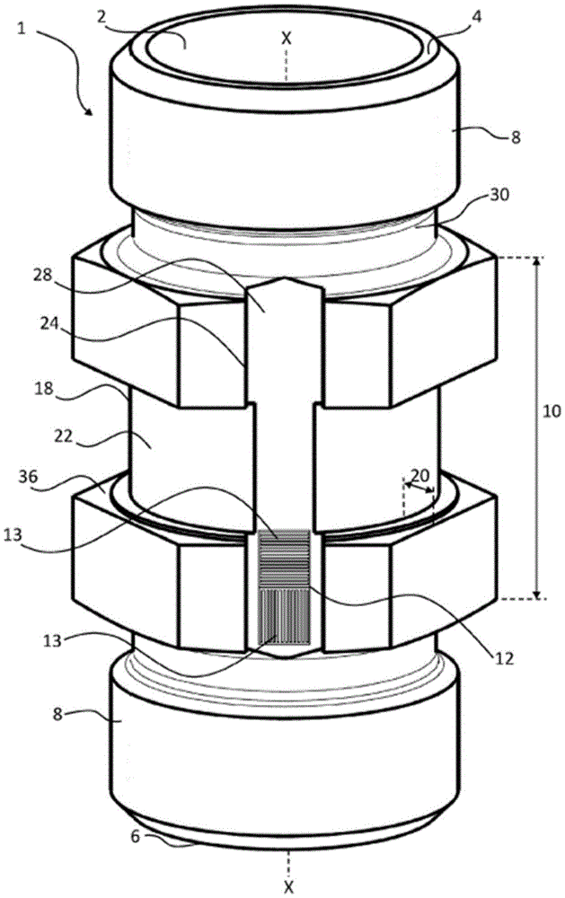
The invention relates to a connection sleeve (1) for a pipeline system for conducting fluids, said connection sleeve having a fluid channel (2) extending along a fluid channel axis (X), wherein the fluid channel (2) can be connected At least the first connection end (4) and the second connection end (6) of the casing (1) are connected to the pipeline channel of the pipeline system. A measuring section (10) is formed between the first connection (4) and the second connection (6), wherein a sensor system for measuring the pressure of the medium flowing in the fluid channel (2) is arranged. The sensor system has a connection interface with which it can be connected to a control unit for measuring the pressure in the fluid channel (2) and has at least two strain gauge sensors for measuring the pressure, the strain The gauge sensors are arranged on the outer wall (14) of the measuring section (10) in a manner offset around the circumference of the fluid channel axis (X). The invention also relates to a control unit for connection to a sensor system for pressure measurement of the fluid pressure of the above-mentioned connecting sleeve (1), said control unit having a device for communicating with said connecting sleeve (1) Connection means for data connection of the sensor system and calculation means for calculating the fluid pressure in said connection sleeve (1) based on the received data and based on line and/or medium specific parameters stored in the control unit.
Description
技术领域technical field
本发明涉及一种用于引导流体的管线系统的连接套管。所述连接套管具有沿流体通道轴线延伸的流体通道,其中所述流体通道可至少在连接套管的第一连接端和第二连接端处与管线系统的管线通道连接。在第一连接端和第二连接端之间形成有测量区段,其中,布置有用于测量在流体通道中流动的介质的压力的传感器系统。所述传感器系统在此具有连接接口,传感器系统通过该连接接口可以连接到用于测量流体通道中的压力的控制单元。此外,本发明包括用于连接到传感器系统的控制单元以用于对连接套管的流体压力进行压力测量。The invention relates to a connecting sleeve for a pipeline system for conducting fluids. The connecting sleeve has a fluid channel extending along a fluid channel axis, wherein the fluid channel can be connected to a line channel of a pipeline system at least at a first connecting end and a second connecting end of the connecting sleeve. A measuring section is formed between the first connection and the second connection, wherein a sensor system for measuring the pressure of the medium flowing in the fluid channel is arranged. The sensor system here has a connection interface via which the sensor system can be connected to a control unit for measuring the pressure in the fluid channel. Furthermore, the invention comprises a control unit for connection to a sensor system for pressure measurement of the fluid pressure of the connecting sleeve.
背景技术Background technique
在引导流体的管线系统中,尤其是液压系统中,最大压力可能高达3200巴,但尤其是最大压力也可能超过3200巴。用于液压系统的传统压力传感器在T形连接套管或为此特殊设置的孔处拧入液压块中。这需要大量的构造花费和大的空间。然后,传感器本身通常使用由敏感材料制成的膜片,该膜片与位于流体通道中的介质接触。由于敏感的膜片,介质兼容性在此被限制,以至于整个管线系统仅适用于特定介质,或者管线系统仅允许对选定介质进行压力监测。特别是,氢气作为介质非常具有腐蚀性。因此,例如,输送氢气的管线系统具有已知传感器的缩短的使用寿命。In line systems conducting fluids, especially in hydraulic systems, the maximum pressure may be as high as 3200 bar, but in particular the maximum pressure may also exceed 3200 bar. Conventional pressure sensors for hydraulic systems are screwed into the hydraulic block at T-connection bushings or holes specially provided for this purpose. This requires considerable construction effort and a large space. The sensor itself then usually uses a diaphragm made of a sensitive material that is in contact with the medium located in the fluid channel. Due to the sensitive diaphragm, the media compatibility is limited here, so that the entire pipeline system is only suitable for certain media, or the pipeline system only allows pressure monitoring for selected media. In particular, hydrogen gas is very corrosive as a medium. Thus, for example, pipeline systems conveying hydrogen have a shortened service life of known sensors.
另一个缺点在于,通过T型连接套管分支的流量影响。一方面,湍流(这导致流动损失)和气穴现象发生在分支点。在气穴现象中,由于介质中的剪切运动产生空气离析(Luftausscheidung)。空气离析发生与温度相关的燃烧,根据柴油效应,这会导致介质,特别是油老化,并收集沉积物或燃烧残留物。因此,气穴现象和柴油效应意味着,管线系统必须更频繁地维护,并且管线系统的使用寿命会缩短。Another disadvantage is the influence of the flow through the T-junction bushing branches. On the one hand, turbulence (which causes flow losses) and cavitation occur at branch points. In cavitation, air segregation occurs as a result of shear movements in the medium. Air segregation takes place in temperature-dependent combustion, which, according to the diesel effect, leads to the aging of the medium, especially the oil, and the collection of deposits or combustion residues. Consequently, cavitation and the diesel effect mean that the piping system must be maintained more frequently and the life of the piping system is shortened.
发明内容Contents of the invention
本发明的目的在于提供一种连接套管,该连接套管解决了现有技术中已知的问题,特别是优化了使用寿命和维护间隔并且优选地优化了与介质相关的可用性,有利地减少了流动损失。The object of the present invention is to provide a connecting sleeve which solves the problems known from the prior art, in particular optimizes the service life and maintenance intervals and preferably optimizes the medium-related availability, advantageously reducing flow loss.
根据本发明,该目的通过根据权利要求1所述的连接套管的特征以如下方式解决,即用于测量压力的传感器系统具有至少两个应变仪传感器,它们在围绕流体通道轴线的周边上错开地设置在测量区段的外壁上。According to the invention, this object is solved by the features of the connecting sleeve according to
管线系统内的高压会导致相关部件,尤其是连接套管在弹性范围略微扩大。连接套管的材料相应地在压力下向各个方向拉伸。这种不可见的伸展由布置在连接套管上的应变仪传感器记录并作为物理变化、尤其是作为电阻变化或作为电压变化输出,或者通过连接接口转发给控制单元。本发明在此基于这样的发现,即管线系统中的压力可以通过测量在连接套管处发生的应变或长度变化并对其进行阐明来推断。连接套管长度的变化在此与管线系统中记录的压力直接相关,从而用作压力传感器的应变计不会与管线系统中引导的介质接触。High pressures in the pipeline system cause the associated components, especially the connecting sleeves, to expand slightly in the elastic range. The material of the connection sleeve is accordingly stretched in all directions under pressure. This invisible stretch is registered by a strain gauge sensor arranged on the connecting sleeve and output as a physical change, in particular as a resistance change or as a voltage change, or forwarded via the connection interface to the control unit. The invention is based here on the discovery that the pressure in a pipeline system can be inferred by measuring and interpreting the strains or length changes that occur at connecting sleeves. The change in the length of the connecting sleeve is directly related to the pressure registered in the pipeline system, so that the strain gauges used as pressure sensors do not come into contact with the medium conducted in the pipeline system.
根据本发明的连接套管还实现了一种测量方法,该测量方法可以容易且节省空间地改装到现有的管线系统中并且可以适用于几乎任何介质,唯一的前提是连接套管本身,即其材料适用于这种介质。这意味着传感器系统也可以用于腐蚀性介质,例如氢气,针对其目前很难找到合适的传感器或很昂贵。The connection sleeve according to the invention also enables a measuring method which can be easily and space-saving retrofitted into existing pipeline systems and which can be adapted to almost any medium, the only prerequisite being the connection sleeve itself, i.e. Its material is suitable for this medium. This means that the sensor system can also be used for aggressive media, such as hydrogen, for which suitable sensors are currently difficult or expensive to find.
优选地,应变仪传感器绕流体通道轴线在周边上以90°或180°分布地设置。特别地,应变仪传感器沿流体通道轴线彼此错开地设置。由此,外部影响、例如由外部作用产生到管线系统上的应变或应力可以已经通过应变仪传感器的布置和互连(Verschaltung)补偿。区分由外部引起的应变和由内部引起的应变是有利的,这可以得出关于管线系统中的压力的结论。Preferably, the strain gauge sensors are arranged distributed over the circumference at 90° or 180° around the axis of the fluid channel. In particular, the strain gauge sensors are arranged offset from one another along the fluid channel axis. As a result, external influences, for example strains or stresses on the pipeline system caused by external effects, can already be compensated for by the arrangement and interconnection of the strain gauge sensors. It is advantageous to distinguish between externally induced strains and internally induced strains, which allow conclusions to be drawn about the pressure in the pipeline system.
特别有利的是,应变仪传感器设计为分别具有至少一个应变测量传感器的应变计。It is particularly advantageous if the strain gauge sensors are designed as strain gauges each having at least one strain measuring sensor.
有利地,应变计分别具有在载体膜上的应变测量传感器。优选地,应变计分别具有在载体膜上的两个应变测量传感器,其中,第一应变测量传感器测量沿纵向方向的纵向应变,第二应变测量传感器测量在横向方向上的横向应变。在此有利地,相应载体箔膜上的两个应变测量传感器相对彼此旋转90°并且在相对于流体通道轴线的纵向方向上依次地布置。Advantageously, the strain gauges each have a strain-measuring sensor on the carrier film. Preferably, the strain gauges each have two strain-measuring sensors on the carrier film, wherein a first strain-measuring sensor measures a longitudinal strain in the longitudinal direction and a second strain-measuring sensor measures a transverse strain in the transverse direction. Advantageously, the two strain-measuring sensors on the respective carrier foil are rotated by 90° relative to each other and are arranged one behind the other in the longitudinal direction relative to the fluid channel axis.
在本发明的有利实施方式中,传感器系统中的应变计的应变测量传感器电连接以形成全惠斯登电桥(Wheatstone’schen Vollbrücke)。特殊的电路布置具有补偿温度和振动的优点。特别地,在此连接套管具有四个有源应变测量传感器。In an advantageous embodiment of the invention, the strain measuring sensors of the strain gauges in the sensor system are electrically connected to form a full Wheatstone bridge. A special circuit arrangement has the advantage of compensating for temperature and vibration. In particular, the connecting sleeve here has four active strain-measuring sensors.
有利地,至少一个应变测量传感器电连接在传感器系统中用于电阻查询。该电路优选地与用于测量压力或应变的电路并联设置。有利地,多个应变测量传感器也可以分别在用于电阻查询的切换布置中单独切换,以便提高测量质量。各个应变测量传感器的并联延伸的电阻查询可以得出关于振动的结论。由此得出的优点是,传感器系统能够在压力测量的同时进行振动检测。Advantageously, at least one strain gauge sensor is electrically connected in the sensor system for resistance interrogation. This circuit is preferably arranged in parallel with the circuit for measuring pressure or strain. Advantageously, a plurality of strain measurement sensors can also be individually switched in each switching arrangement for resistance interrogation in order to increase the measurement quality. A parallel-running resistance interrogation of the individual strain-measuring sensors allows conclusions about the vibrations to be drawn. This results in the advantage that the sensor system is able to detect vibrations simultaneously with the pressure measurement.
有利地,在测量区段的外壁中设计有围绕测量区段的外壁周向延伸的、特别是完全周向延伸的接收槽,该接收槽用于集成传感器系统和/或应变仪传感器的电子电路。接收槽改善了保护能力,并减少了用于传感器系统的安装空间。Advantageously, a receiving groove extending circumferentially around the outer wall of the measuring section, in particular extending completely circumferentially, is formed in the outer wall of the measuring section for integrating the electronic circuit of the sensor system and/or the strain gauge sensor . The receiving groove improves protection and reduces the installation space for the sensor system.
优选地,应变仪传感器分别布置在测量槽中,测量槽形成在测量区段的外壁中并且平行于流体通道轴线延伸。在另一实施例中,测量槽沿流体通道轴线在测量区段的整个轴向延伸上延伸。通过引入两个测量槽,还有利地记录测量区段的更高程度的应变。Preferably, the strain gauge sensors are respectively arranged in measuring grooves formed in the outer wall of the measuring section and extending parallel to the fluid channel axis. In a further embodiment, the measuring groove extends along the fluid channel axis over the entire axial extension of the measuring section. By introducing two measuring grooves, a higher degree of strain of the measuring section is also advantageously registered.
关于连接套管的使用场所、外部影响和由此产生的使用寿命,根据一个优选实施例,连接套管至少在背离流体管道的外表面上具有涂层,尤其是防腐蚀涂层(Korrosionsbeschichtung)。与应变计组合的优点是,应变计有利地布置在涂层上,特别是防腐蚀涂层上。有利地,防腐蚀涂层设计为锌镍层的形式。特别地,应变计布置在涂层上的优点是,连接套管的制造和涂覆可以更容易,并且在连接套管被涂覆时不会损坏传感器系统。With regard to the location of use of the connecting sleeve, external influences and the resulting service life, according to a preferred embodiment, the connecting sleeve has a coating, in particular a corrosion-resistant coating, at least on its outer surface facing away from the fluid line. The advantage of the combination with the strain gauges is that the strain gauges are advantageously arranged on the coating, in particular on the anti-corrosion coating. Advantageously, the anti-corrosion coating is designed in the form of a zinc-nickel layer. In particular, the arrangement of the strain gauges on the coating has the advantage that the production and coating of the connecting sleeve can be made easier and that the sensor system is not damaged when the connecting sleeve is coated.
特别有利地,传感器系统的连接接口设计为电感应连接接口。尤其是可以通过该连接接口将供电电压传输给传感器系统或应变仪。在这种情况下,感应供电电压可以借助夹子传输,其中夹子在此夹住连接套管,尤其是以力和形状配合(kraftformschlüssig)的方式。Particularly advantageously, the connection interface of the sensor system is designed as an inductive connection interface. In particular, the supply voltage can be transmitted to sensor systems or strain gauges via the connection interface. In this case, the inductive supply voltage can be transmitted by means of a clip, wherein the clip grips the connecting sleeve here, in particular in a non-positive and positive manner.
优选地,传感器系统的连接接口设计为无电缆或无线连接接口,通过该连接接口可以从传感器系统传输数据和/或向传感器系统传输数据。例如,无线或无电缆连接接口设计为电感应或无线电或蓝牙或WiFi连接接口。Preferably, the connection interface of the sensor system is designed as a cable-free or wireless connection interface, via which data can be transmitted from and/or to the sensor system. For example, wireless or cable-free connection interfaces are designed as inductive or radio or Bluetooth or WiFi connection interfaces.
有利地,电感应连接接口设置在接收槽中。在一个有利的实施例中,可以通过连接接口从传感器系统传输数据和/或向传感器系统传输数据。特别有利地,电压输入和测量信号输出都通过相同的连接接口进行。Advantageously, the inductive connection interface is arranged in the receiving groove. In an advantageous embodiment, data can be transmitted from and/or to the sensor system via the connection interface. It is particularly advantageous if both the voltage input and the measurement signal output take place via the same connection interface.
为了借助感应传输将传感器系统连接到控制单元,夹子优选地通过电缆与控制单元连接。夹子包围接收槽和设置在其中的传感器系统或传感器系统的连接接口。夹子可以在此设计成,其可以通过装配工手动装配在连接接口上,特别是装配在接收槽上。优选地,夹子在弹性区域中通过手动或工具被加宽,然后借助弹性回弹被夹持、卡锁或夹紧在连接套管上。替代地,夹子可以塑性变形,特别是在温度的影响下,并且用手和/或用工具压到或成型到连接套管上。In order to connect the sensor system to the control unit by means of inductive transmission, the clip is preferably connected to the control unit via a cable. The clip surrounds the receiving groove and the sensor system or the connection interface of the sensor system arranged therein. The clip can here be designed such that it can be fitted manually by a fitter on the connection interface, in particular on the receiving groove. Preferably, the clamp is widened manually or with a tool in the elastic region and is then clamped, latched or clamped on the connecting sleeve by means of elastic springback. Alternatively, the clip can be deformed plastically, in particular under the influence of temperature, and pressed or formed onto the connecting sleeve by hand and/or with a tool.
根据替代的实施例,电压源设置在连接套管本身上。电源电压可以借助电压源施加到传感器系统上。电压源有利地是电池,其尤其布置在接收槽中。该电压源可以省去外部电压供应。这种改进方案在偏远或难以到达的使用位置特别有利。According to an alternative embodiment, the voltage source is arranged on the connection sleeve itself. The supply voltage can be applied to the sensor system by means of a voltage source. The voltage source is advantageously a battery, which is arranged in particular in the receiving tank. This voltage source can save an external voltage supply. This refinement is particularly advantageous in remote or difficult-to-reach locations of use.
已证明优选实施例对于困难的使用位置特别有利,根据该实施例,传感器系统的连接接口被设计为发射器元件和/或接收器元件,以用于产生无线电或蓝牙或WiFi信号或用于接收这些信号。特别地,控制单元具有与上述发射器元件或接收器元件相对应设计或配置的发射器元件或接收器元件。尤其是,传感器系统与控制单元之间无需有线连接,这扩展了连接套管的应用位置和控制单元的取回位置的多样性。此外,通过铺设单独的线路,降低了事故风险和装配耗费。The preferred embodiment has proven to be particularly advantageous for difficult use positions, according to which the connection interface of the sensor system is designed as a transmitter element and/or receiver element for generating radio or Bluetooth or WiFi signals or for receiving these signals. In particular, the control unit has a transmitter element or receiver element which is designed or configured correspondingly to the above-mentioned transmitter element or receiver element. In particular, no wired connection is required between the sensor system and the control unit, which expands the variety of application locations of the connection sleeve and retrieval locations of the control unit. Furthermore, the risk of accidents and the outlay on assembly are reduced by laying separate lines.
特别地,在这方面,在有利的应用中,控制单元被设计为移动设备,其从连接套管的连接接口出发直接或间接地利用接收器元件接收测量信号。移动设备尤其是移动电话、平板电脑、便携式计算机等。直接连接尤其是例如通过蓝牙的连接,其中控制单元和传感器系统彼此直接通信。间接连接尤其是一种其中设备例如网络设备被接通以便例如通过基于WiFi的连接使测量信号可用于网络的连接。特别是,间接连接既能够实现保护的、受限于网络对测量信号的访问,也可以通过互联网远程访问测量信号。In particular, in this respect, in an advantageous application, the control unit is designed as a mobile device, which receives the measurement signal directly or indirectly from the connection interface of the connection sleeve with the receiver element. Mobile devices, especially mobile phones, tablets, laptops, etc. A direct connection is in particular a connection, eg via Bluetooth, in which the control unit and the sensor system communicate directly with each other. An indirect connection is especially a connection in which a device, for example a network device, is switched on in order to make measurement signals available to the network, for example via a WiFi-based connection. In particular, the indirect connection enables both protected, network-limited access to the measurement signals as well as remote access to the measurement signals via the Internet.
此外,本发明的目的通过根据权利要求22的控制单元得以解决,该控制单元用于连接到前述传感器系统,以用于对连接套管的流体压力进行压力测量。Furthermore, the object of the invention is solved by a control unit according to claim 22 for connection to the aforementioned sensor system for pressure measurement of the fluid pressure of the connecting sleeve.
根据本发明,控制单元具有用于与连接套管的传感器系统进行数据技术连接的连接装置和用于基于接收到的数据以及基于存储在控制单元中的线路和/或介质特定参数计算所述连接套管中的流体压力的计算装置。According to the invention, the control unit has connection means for a data-technical connection to the sensor system of the connection bushing and for calculating said connection on the basis of the received data and on the basis of line and/or medium-specific parameters stored in the control unit Calculation device of fluid pressure in casing.
特别有利地,除了纯压力测量和可选的振动测量之外,本发明还优选地能够确定位于流体通道中的介质的温度。有利地,控制单元的计算装置设计为根据测量数据和参数计算位于流体通道中的介质的温度。有利地,初始位置的参考点通过至少介质的已知温度和测量区段中的已知应变来确定,由此可以通过相对应变以及包括管线和/或特定介质参数得出关于介质温度的结论。Particularly advantageously, in addition to the pure pressure measurement and the optional vibration measurement, the invention preferably also makes it possible to determine the temperature of the medium located in the fluid channel. Advantageously, the calculation means of the control unit are designed to calculate the temperature of the medium located in the fluid channel from the measured data and parameters. Advantageously, the reference point of the initial position is determined by at least a known temperature of the medium and a known strain in the measurement section, whereby conclusions can be drawn about the temperature of the medium by means of the relative strain and including line and/or specific medium parameters.
附图说明Description of drawings
从以下的附图描述和从属权利要求中得出本发明的进一步有利的设计方案。Further advantageous embodiments of the invention emerge from the following description of the figures and the subclaims.
附图中:In the attached picture:
图1示出了连接套管的第一实施例的透视图,Figure 1 shows a perspective view of a first embodiment of a connecting sleeve,
图2示出了根据图1的连接套管在根据图1的流体轴线的轴向方向上的俯视图,FIG. 2 shows a top view of the connecting sleeve according to FIG. 1 in the axial direction of the fluid axis according to FIG. 1 ,
图3示出了具有两个应变计的载体膜的示意图,Figure 3 shows a schematic diagram of a carrier membrane with two strain gauges,
图4示出了沿根据图1的流体轴线X的纵向截面,Figure 4 shows a longitudinal section along the fluid axis X according to Figure 1,
图5示出了具有铸造(vergossen)的测量槽和接收槽的连接套管的第二实施例的透视图,FIG. 5 shows a perspective view of a second embodiment of a connecting sleeve with cast measuring grooves and receiving grooves,
图6示出了具有部分铸造的测量槽和接收槽的连接套管的第三实施例的透视图,Figure 6 shows a perspective view of a third embodiment of a connecting sleeve with a partially cast measuring and receiving groove,
图7和图8示出了根据图6的具有控制单元的连接套管的第三实施例的连接顺序的透视图,Figures 7 and 8 show perspective views of the connection sequence of the third embodiment of the connection sleeve with the control unit according to Figure 6,
图9示出了具有接收槽的连接套管的第四实施例的透视图,Figure 9 shows a perspective view of a fourth embodiment of a connecting sleeve with a receiving groove,
图10示出了具有部分铸造的接收槽的连接套管的第五实施例的透视图。FIG. 10 shows a perspective view of a fifth embodiment of a connecting sleeve with a partially cast receiving groove.
在附图的各个图中,相同的部件始终设置有相同的附图标记。In the various figures of the drawings, identical components are always provided with the same reference numerals.
具体实施方式detailed description
对于随后的描述要声称的是,本发明不限于实施例并且在此不限于所描述的特征组合的全部或若干特征,更确切地,该/每个实施例的每个单个的部分特征也可与所有其它与其相关地描述的部分特征分离,其本身以及与另一实施例的任意特征的组合对于本发明的主题也具有重要意义。For the ensuing description it is claimed that the invention is not limited to the embodiments and hereby not to all or several features of the described feature combinations, rather each individual partial feature of the/each embodiment may also be Separately from all other partial features described in connection therewith, they are also relevant to the subject-matter of the invention on their own and in combination with any feature of another exemplary embodiment.
在图1、5、6、9和10中分别示出了用于引导流体的管线系统的连接套管1。该连接套管1具有沿流体轴线X延伸的流体通道2,其中流体通道2可以在连接套管1的至少第一连接端4和第二连接端6处与管线系统的管线通道连接。管线系统的管线通道未在图中示出。1 , 5 , 6 , 9 and 10 each show a connecting
连接套管1的连接端4、6可以在此设计成,使得连接套管1可以与管道或机组连接。特别地,至少一个连接端4、6具有从流体通道2向外指向的外螺纹8以用于装配管道或拧入机组中。或者,至少一个连接端4、6具有指向流体通道2的内螺纹,以用于拧入机组的适配器元件的拧入或管道的拧入。至少一个连接端4、6有利地设计为心轴和/或套筒和/或插头。至少一个连接端4、6有利地通过材料配合的方式连接到机组或管道,特别是通过焊接、钎焊或胶合。根据一个特别优选的实施例,在两个连接端4、6上形成外螺纹8,以用于拧到管道或机组上,如图1和图5至图10示意性所示。The connection ends 4 , 6 of the
如图1所示,在第一连接端4和第二连接端6之间形成测量区段10。用于测量在流体通道中流动的介质的压力的传感器系统布置在该测量区段10中。传感器系统在此具有连接接口,传感器系统通过该连接接口可以连接到用于测量流体通道2中的压力的控制单元。为了简单起见,连接接口和控制单元未在图1中示出。As shown in FIG. 1 , a
根据本发明,用于压力测量的传感器系统具有至少两个应变仪传感器。如图2所示,在此应变仪传感器围绕流体通道轴线X在周边上错开地布置在测量区段10的外壁14上。According to the invention, a sensor system for pressure measurement has at least two strain gauge sensors. As shown in FIG. 2 , the strain gauge sensors are arranged circumferentially offset around the fluid channel axis X on the
图2中所示的连接套管1对应于优选实施方式,根据该优选实施方式,应变仪传感器围绕流体通道轴线X错开180°布置在周边上。根据未示出的另一实施例,应变仪传感器绕流体通道轴线X错开90°地布置在周边上。The connecting
特别优选地,根据图4所示实施例的应变仪传感器沿流体通道轴线X彼此错开地布置。Particularly preferably, the strain gauge sensors according to the embodiment shown in FIG. 4 are arranged offset from one another along the axis X of the fluid channel.
应变仪传感器记录测量区段10中的应变,特别是人眼不可见的应变,并将这些作为测量信号输出,特别是以电阻变化或电压变化的形式。The strain gauge sensor registers strains in the measuring
通过测量在连接套管1处产生的应变或长度变化并阐明测量信号,特别是借助控制单元,可以确定管线系统中的压力。连接套管1的长度变化在此与管线系统中记录的压力直接相关。根据图1中应变计12的布置,用作用于压力测量的传感器的应变仪传感器不与管线系统中引导的介质接触。特别地,由此使得根据本发明的连接套管1适用于管线系统中的几乎任何介质,唯一的要求是连接套管1本身,即其材料,适用于该介质。这意味着传感器系统也可以用于腐蚀性介质,例如氢气,针对其只有少数或更昂贵的合适的压力传感器。By measuring the strain or length change occurring at the connecting
如图1、5、6、9和10所示,具有根据本发明的连接套管1的传感器系统节省空间并且可以容易地改装到现有的管线系统中。As shown in Figures 1, 5, 6, 9 and 10, a sensor system with a connecting
特别地,如图2和4所示,通过连接套管1上的应变仪传感器的绕流体通道轴线X错开180°的布置可以使从外部施加的影响,例如由装配力引起的应变或张力已经通过应变仪传感器的布置和互连得到补偿。有利地,可以区分由外部引起的应变和由内部引起的应变,从而可以得出关于管线系统中的压力的结论。In particular, as shown in FIGS. 2 and 4 , the arrangement of the strain gauge sensors on the connecting
应变仪传感器特别有利地设计为应变计12,如图1和图3示意性所示,每个应变计具有至少一个应变测量传感器13。The strain gauge sensors are particularly advantageously designed as strain gauges 12 , each of which has at least one
特别地,如图1所示,应变计12沿流体通道轴线X在其纵向方向上延伸。In particular, as shown in FIG. 1 , the
有利地,至少一个应变测量传感器13布置在载体膜16上。如图1和图3中所示,应变计12优选地分别在载体膜16上具有两个应变测量传感器13。特别地,第一应变测量传感器13测量沿纵向方向的应变,第二应变测量传感器13测量沿横向方向的应变。载体膜16特别优选与连接套管1材料配合地连接。如图1和图3所示,应变测量传感器13有利地以材料配合的方式与载体膜16连接。Advantageously, at least one
图1所示的连接套管1对应于具有两个应变计12和四个应变测量传感器13的优选实施方式,其中每两个应变测量传感器13彼此相邻布置在公共载体膜16上,如图3所示。The connecting
在本发明的有利实施方式中,传感器系统中的应变测量传感器13被电连接以形成全惠斯登电桥。由于全惠斯登电桥电路本身是已知的,因此为了更好地概览,图中没有示出。特别地,连接套管1在此具有四个有源应变测量传感器13,优选每两个应变测量传感器13在一个载体膜16上,其中每个载体膜16的一个应变测量传感器13测量沿流体通道轴线X的纵向应变,并且一个应变计12测量连接套管1的横向或周向应变。例如,连接套管1的图1所示的实施例具有至少一个这样的应变计12。具有载体膜16和两个应变测量传感器13的应变计12的实施例在图3中示意性地示出。在此有利地,如图3所示,载体膜16上的两个应变测量传感器13相对彼此旋转90°,并在相对于流体通道轴线X的纵向方向上一个接一个地布置。In an advantageous embodiment of the invention, the
与全惠斯登电桥的互连有利地使弯曲、振动和温度影响能够在测量中得到补偿,并且法向应变,即相对于流体通道轴线X的轴向,可以独立于弯曲应变进行测量。另一个优点是,与全惠斯登电桥的互连会产生高输出信号或测量信号以及出色的共模抑制(CMR)。The interconnection with a full Wheatstone bridge advantageously enables bending, vibration and temperature effects to be compensated for in the measurement, and normal strain, ie axial with respect to the fluid channel axis X, can be measured independently of bending strain. Another advantage is that the interconnection with a full Wheatstone bridge results in a high output or measurement signal and excellent common-mode rejection (CMR).
有利地,至少一个单独的应变测量传感器13电连接在传感器系统中以用于电阻查询。对应于全惠斯登电桥电路,省略了用于各应变计12的电阻查询的电路布置的图示。该电路优选与压力或应变测量电路并联,特别是与全惠斯登电桥电路并联设置。有利地,多个应变测量传感器13也可以分别单独地在传感器系统中接入,以进行电阻查询,以便借助数据比较例如形成平均值来改善测量质量。各应变测量传感器13的并联电阻查询能够实现连接套管1中的振动的测量。Advantageously, at least one individual
特别地,应变计12是高度敏感的应变计12,其可以有利地将应变以至少10-4mm的精度输出到控制单元。In particular, the
根据一个实施例,应变计12设计为膜应变计。在这种情况下,压阻式应变计,通常是电阻丝,优选地应用于载体膜16。膜有利地用作能够在连接套管1上装配、特别是胶合的装置。According to one embodiment, the
根据另一实施例,应变计12设计为硅应变计。有利地,硅应变计提供非常高的灵敏度,同时尺寸很小。硅应变计优选通过粘接或玻璃焊接方法装配在连接套管1上。有利地,通过选择玻璃化(Aufglassung)获得替代的、可能成本更有利的装配方法。According to another embodiment, the strain gauges 12 are designed as silicon strain gauges. Advantageously, silicon strain gauges provide very high sensitivity while being small in size. The silicon strain gauges are preferably mounted on the connecting
有利地,应变计12,特别是硅应变计12通过粘接和玻璃焊接方法的结合装配在连接套管1上。硅应变计12优选首先被玻璃化到载体膜16上。然后将该载体膜16胶合到连接套管1上。这种材料配合的连接的组合具有的优点是,通过增加由载体膜16产生的面,与硅应变计的直接胶合相比,可以减少蠕变效应。同时,可以借助胶合执行到连接套管1上的简单装配。由此简化了直接玻璃化的复杂过程。当直接玻璃化到构件上时,整个构件会被液态玻璃焊料加热并持续冷却,从而不会出现应力裂纹。另一方面,可以可靠地并且不依赖于构件,尤其是不依赖于连接套管1执行到载体膜16上的玻璃化。Advantageously, strain gauges 12 , in particular
根据另一实施例,应变计12设计为薄膜应变计。类似于膜应变计,薄膜应变计有利地是一种将压阻式应变计应用在载体膜16上的技术。薄膜应变计有利地在薄膜印刷方法中制造。According to another embodiment, the
根据另一实施例,应变计12设计为厚膜应变计。有利的是压阻膏,其在印刷方法中直接施加在连接套管1上。According to another embodiment, the
作为应变计12的替代方案,应变仪传感器被设计为压电陶瓷传感器。一旦机械压力施加到连接套管1上,压电陶瓷传感器就有利地产生电压。然后可以将产生的电压作为测量信号进行评估。As an alternative to the
根据应变计12和压电陶瓷传感器的另一替代方案,可以使用电容测量方法。特别地,连接套管1的应变代表电容器的极板向固定极板的位移。通过距离变化有利地得出电容的变化。电容变化又可以作为测量信号进行评估。According to another alternative of
在前述应变仪传感器的另一替代方案中,使用感应测量方法。为了检测连接套管的应变,检测至测量电感器
特别地,应变仪传感器分别布置在测量槽24中。该测量槽24形成在测量区段10的外壁14中并且平行于流体通道轴线X延伸。在图1、2和图4至8中,测量槽24形成为,使得连接套管1的测量槽24在测量区段10的整个轴向范围延伸。有利地,根据未示出的示例,多于一个的应变仪传感器也可以布置在共同的测量槽24中。特别有利地,测量槽24关于流体通道轴线X对称地形成和/或具有平坦的、平行于流体通道轴线X延伸的测量槽底部28。通过连接套管1的材料去除,两个测量槽24的引入进一步有利地导致测量区段10中的更高程度的应变。In particular, strain gauge sensors are respectively arranged in the measuring
如图2所示,测量槽24具有相对于流体通道轴线X径向朝向测量槽底部28形成的测量槽深度26,其中,连接套管1的壁以剩余壁厚保持在测量槽底部28和流体通道2之间。有利地,测量槽24的测量槽底部28的测量槽深度26最多对应于连接套管1在测量区段10外部的最小外周。As shown in FIG. 2 , the measuring
测量槽深度26和壁的剩余壁厚设计为,使得至少在功能管线系统中出现的最大内压不会导致连接套管1的塑性变形。特别地,连接套管1的测量槽深度26和剩余壁厚在此设计为与流体通道2中的内部压力适配为,使得连接套管1可以优选在流体通道2中加载特别是3200巴的最大内部压力、有利地超过3200巴,而其没有塑性变形。有利地,测量槽深度26和剩余壁厚设计为与流体通道2中的内部压力适配为,使得连接套管1可以加载安全压力而不发生塑性变形。安全压力尤其是通过将流体通道2中的最大内部压力乘以安全系数来形成。安全系数特别是1.5到6.5、优选2到6、优选3到5、特别优选4。The measuring
如图1、6、7、9和10所示,在一个有利的实施例中,在测量区段10的外壁14中形成有沿周向围绕测量区段10的外壁14延伸的接收槽18。有利地,该环绕的接收槽18用于集成传感器系统的电路和/或特别是用于应变仪传感器的传感器系统的连接接口和/或特别优选用于集成应变仪传感器。例如,图9和10中的应变仪传感器集成在环绕的接收槽18中。通过连接套管1中的接收槽18在此避免了传感器系统在连接套管1上的无序排列。传感器系统在此未在图1、6、7、9和10中示出。特别地,电路可以包括电导体和/或印刷电路板和/或电压源和/或其他电路元件。连接接口尤其设计为发射器和/或接收器和/或插头和/或插座和/或连接电缆。应变仪传感器在接收槽18中的布置一方面具有制造技术优势,因为环绕的接收槽18更容易制造,另一方面具有避免由装配工具例如开口扳手造成的损坏的优点。As shown in FIGS. 1 , 6 , 7 , 9 and 10 , in an advantageous embodiment, a receiving
特别有利地,应变仪传感器分别布置在接收槽18中的扁平部42中,如图9所示,或者布置在测量槽24中的扁平部42中或布置在测量槽24和接收槽18之间的过渡区域中。扁平部42在此提供额外的保护。扁平部42特别在环绕的接收槽18中比在轴向测量槽24中更容易制造。Particularly advantageously, the strain gauge sensors are respectively arranged in the flat 42 in the receiving
如图1和图5至图10所示,接收槽18优选设置在连接套管1的中部。接收槽18在此优选地具有相对于流体通道轴线X径向朝接收槽底部22形成的接收槽深度20,其中,连接套管1的壁以剩余壁厚保持在接收槽底部22和流体通道2之间。接收槽深度20和壁的剩余壁厚设计为,使得至少在功能管线系统中出现的最大内压不会导致连接套管1的塑性变形。特别地,接收槽深度20和连接套管1的剩余壁厚根据与测量槽24关于测量槽深度26和连接套管1的剩余壁厚相同的压力设计要求来设计。As shown in FIG. 1 and FIGS. 5 to 10 , the receiving
接收槽18和测量槽24特别地分别对传感器系统具有保护作用,特别是对应变仪传感器和/或电路和/或连接接口具有保护作用。The receiving
连接套管1设计有背离流体通道2的外表面30。该外表面30优选地具有涂层,特别是防腐蚀涂层。该涂层具有特别的优点,即连接套管1更加抵抗外部影响并且提高了连接套管1的使用寿命。The connecting
特别优选地,应变计12有利地布置在涂层上,特别是防腐蚀涂层上。防腐蚀涂层特别优选设计为锌镍层。有利地,使用具有透明或黑色钝化的锌镍层。特别地,钝化是在锌镍层上形成的无机转化层,其是通过浸入到适合该目的的化学品溶液中而形成的。在此,该溶液有利地是三价铬化合物。特别地,应变计12设置在涂层上的优点是,连接套管1的制造和涂覆可更容易,并且在连接套管1被涂覆时应变计12不会被损坏。Particularly preferably, the
根据未示出的有利实施例,电压源设置在连接套管1本身上。电源电压可以借助电压源施加到传感器系统上。电压源有利地是电池并且尤其布置在接收槽18中。电压源可以省去外部电压供应并且增加连接套管1的独立性,特别是结合无电缆或无线数据传输。这种构造在偏远或难以到达的使用位置特别有利。According to an advantageous embodiment not shown, the voltage source is arranged on the
特别有利地,传感器系统的连接接口设计为电感应连接接口。特别地,如图8所示,供电电压可以通过连接接口传输到传感器系统上。在这种情况下,供电电压可以电感应地借助图7和图8中所示的夹子32传递。根据图8,夹子32特别是力配合地设置在测量区段10中,特别是在接收槽18中。Particularly advantageously, the connection interface of the sensor system is designed as an inductive connection interface. In particular, as shown in FIG. 8 , the supply voltage can be transferred to the sensor system via the connection interface. In this case, the supply voltage can be transferred inductively by means of the
传感器系统的连接接口有利地设计为无电缆或无线连接接口,通过该连接接口可以从传感器系统和/或向传感器系统传输数据。例如,无线或无电缆连接接口可以设计为电感应或无线电或蓝牙或WiFi连接接口。The connection interface of the sensor system is advantageously designed as a cable-free or wireless connection interface via which data can be transmitted from and/or to the sensor system. For example, the wireless or cable-free connection interface can be designed as an inductive or radio or Bluetooth or WiFi connection interface.
特别地,在图8所示的实施方式中,传感器系统借助电感应连接接口连接到控制单元。特别地,控制单元通过电缆连接到夹子32,在图7和图8中,在夹子32上仅示出了用于与电缆连接的插头34。优选地,如图8所示,连接电缆的夹子32包围接收槽18和设置在其中的连接接口。特别地,接收槽18的沿轴向方向指向流体通道轴线X的侧壁36防止夹子32轴向移位。In particular, in the embodiment shown in FIG. 8 the sensor system is connected to the control unit by means of an inductive connection interface. In particular, the control unit is connected to the
在有利的实施例中,传感器系统的连接接口被设计为电感应连接接口,通过该连接接口可以从传感器系统传输数据和/或向传感器系统传输数据。特别地,供电电压从控制单元出发以感应方式传输到传感器系统上,并且优选地,测量信号、作为电阻变化或作为电压变化输出的应变被传输到控制单元上。特别有利地,电压输入和测量信号输出都通过相同的连接接口进行,特别是如图8所示的被夹子32包围的连接接口。In an advantageous exemplary embodiment, the connection interface of the sensor system is designed as an inductive connection interface, via which data can be transmitted from and/or to the sensor system. In particular, the supply voltage is transmitted inductively from the control unit to the sensor system, and preferably the measurement signal, the strain output as a change in resistance or as a change in voltage, is transmitted to the control unit. Particularly advantageously, both the voltage input and the measurement signal output take place via the same connection interface, in particular the connection interface enclosed by the
夹子32优选地设计成,使得它可以由装配工手动装配在连接接口上,特别是装配在接收槽18上。优选地,夹子32在弹性区域中通过手动或工具被加宽,然后借助弹性回弹被夹持、卡锁或夹紧在连接套管1上。替代地,夹子32可以塑性变形,特别是在温度的影响下,并且用手和/或用工具压在或成型到连接套管1上。夹子32有利地利用力和形状配合的布置设置在连接套管1上。The
为了改进连接套管1的应用范围,传感器系统的连接接口在未示出的有利实施例中被设计为发射器元件和/或接收器元件,以用于产生和/或接收无线电或蓝牙或WiFi信号。在此,控制单元具有与上述发射器元件和/或接收器元件相对应设计和配置的发射器元件和/或接收器元件。尤其可以省去从控制单元到传感器系统的有线连接,这扩展了连接套管1的应用位置和控制单元的取回位置的多样性。此外,通过铺设单独的电线路,降低了事故风险和装配花费。在这个意义上,连接套管1特别有利地具有发射器元件和/或接收器元件以及布置在连接套管1上的电压源。In order to improve the range of applications of the
特别有利地,控制单元是移动设备,其从连接套管1的连接接口出发直接或间接地利用接收器元件接收测量信号。移动设备尤其是移动电话、平板电脑、便携式计算机等。直接连接尤其是例如通过蓝牙的连接,其中控制单元和传感器系统彼此直接通信。间接连接尤其是一种其中设备例如网络设备被接通以便例如通过基于WiFi的连接使测量信号可用于网络的连接。特别是,间接连接既能够实现保护的、受限于网络的对测量信号的访问,也可以通过互联网远程访问测量信号。Particularly advantageously, the control unit is a mobile device which receives the measurement signal directly or indirectly via the receiver element from the connection interface of the
根据图5至8和10中的有利实施例,测量区段10至少部分地连同应变计仪传感器、特别是连同传感器系统、特别是连接接口和/或电压源用塑料38铸造。特别地,如果连接接口通过电缆连接到控制单元,则优选地形成至少一个用于连接电缆的连接点。According to an advantageous embodiment in FIGS. 5 to 8 and 10 , the measuring
特别是在图5中,特别是在整个测量槽深度26和/或接收槽深度20上用塑料38铸造整个测量槽24和接收槽18,从而产生连接套管1的测量区段10的光滑或均匀的外壁14。在根据图9的仅具有接收槽18的示例性实施例中,根据未示出的实施例,可以有利地在整个接收槽深度20上用塑料38铸造接收槽18。In particular in FIG. 5 , the entire measuring
在图6至图8和图10所示的示例性实施例中,有利地部分地在测量槽深度26和接收槽深度20上铸造测量槽24和/或接收槽18。在根据图10的仅具有接收槽18的示例性实施例中,有利地部分地在接收槽深度20上用塑料38铸造接收槽18。特别地,保留接收槽18的剩余侧壁40,使得用于接触铸造的连接点的夹子32或其它连接元件可以布置在剩余的接收槽18中。In the exemplary embodiment shown in FIGS. 6 to 8 and 10 , the measuring
在一种特殊的实施例中,传感器系统具有至少一个用于确定环境温度和/或连接套管1的温度的温度传感器。温度传感器可以通过抵消流体管路中流动的介质的热应变效应来提高压力测量的测量质量。In a special embodiment, the sensor system has at least one temperature sensor for determining the ambient temperature and/or the temperature of the connecting
特别地,连接套管1由钢构成,其涂有锌镍层。然而,替代地,连接套管1也可以由其他材料变型构成,条件是流体通道2中的内部压力在弹性范围内使连接套管1应变或变形,并且变形行为以如下方式已知:控制单元可以阐明内部压力。特别地,变形行为可以通过测试来确定。连接套管1有利地至少部分地由不锈钢或黄铜或塑料38制成。In particular, the connecting
根据本发明,用于连接到用于测量上述类型的连接套管1的流体压力的传感器系统的控制单元具有用于与连接套管1的传感器系统进行数据技术连接的连接装置和基于接收到的数据和基于存储在控制单元中的线路和/或介质特定参数计算所述连接套管1中的流体压力的计算装置。According to the invention, a control unit for connection to a sensor system for measuring the fluid pressure of a connecting
根据控制单元的有利实施例,计算装置被设计为基于测量数据和参数计算位于流体通道中的介质的温度。特别地,控制单元可以通过测量流体通道2中的压力来阐明位于流体通道2中的介质的温度。有利地,初始位置的参考点可以在至少介质的温度已知、和测量区段10中的应变已知的情况下确定。从这个参考点可以通过相对应变在包括管线和/或特定介质参数的情况下得出关于介质温度的结论。According to an advantageous embodiment of the control unit, the calculation means are designed to calculate the temperature of the medium located in the fluid channel on the basis of measurement data and parameters. In particular, the control unit can elucidate the temperature of the medium located in the
根据图7和图8所示的实施例,控制单元优选地具有设计为感应连接接口的连接电缆的夹子32。该夹子特别设计成,包围接收槽18和连接套管1的设置在其中的连接接口。夹子32优选地具有上述关于夹子的一个或多个特征并且装配在连接套管1上,如图7和图8所解释的。According to the embodiment shown in FIGS. 7 and 8 , the control unit preferably has a
本发明不限于图示和描述的实施例,而且还包括在本发明意义中的所有相同作用的实施例。要强调的是,实施例不限于组合的所有特征;更确切地,每个单独的子特征也可以独立于所有其他子特征而具有创造性意义。此外,本发明也不限于权利要求1中限定的特征的组合,而是还可以通过整体公开的所有单独特征的特定特征的任何其他组合来限定。这意味着原则上实际上权利要求1的每个单独的特征可以被省略或被本申请中其他地方公开的至少一个单独的特征代替。The invention is not limited to the illustrated and described embodiments, but also includes all equivalent embodiments within the meaning of the invention. It is emphasized that the embodiments are not limited to all features in combination; rather, each individual sub-feature may also be of inventive significance independently of all other sub-features. Furthermore, the invention is also not limited to the combination of the features defined in
附图标记列表List of reference signs
1 连接套管1 connecting sleeve
2 流体通道2 fluid channels
4 第一连接端4 first connection end
6 第二连接端6 Second connection port
8 外螺纹8 external thread
10 测量区段10 measuring sections
12 应变计12 Strain gauges
13 应变测量传感器13 Strain measurement sensor
14 测量区段的外壁14 Outer wall of the measuring section
16 载体膜16 carrier film
18 接收槽18 receiving slot
20 接收槽深度20 Receiving groove depth
22 接收槽底部22 Receptacle Bottom
24 测量槽24 Measuring slot
26 测量槽深度26 Measuring groove depth
28 测量槽底部28 Measuring tank bottom
30 连接套管的外表面30 External surface of connecting sleeve
32 夹子32 clips
34 插头34 plug
36 接收槽的侧壁36 Side wall of receiving tank
38 塑料38 plastic
40 剩余侧壁40 remaining side walls
42 扁平部42 flat part
X 流体通道轴线X Fluid channel axis
Claims (26)
Applications Claiming Priority (3)
| Application Number | Priority Date | Filing Date | Title |
|---|---|---|---|
| DE102020112982.3 | 2020-05-13 | ||
| DE102020112982.3A DE102020112982A1 (en) | 2020-05-13 | 2020-05-13 | Connection piece for fluid-carrying line systems |
| PCT/EP2021/061514 WO2021228596A1 (en) | 2020-05-13 | 2021-05-03 | Connecting piece for fluid-conducting line systems |
Publications (2)
| Publication Number | Publication Date |
|---|---|
| CN115461601A true CN115461601A (en) | 2022-12-09 |
| CN115461601B CN115461601B (en) | 2026-05-05 |
Family
ID=75850184
Family Applications (1)
| Application Number | Title | Priority Date | Filing Date |
|---|---|---|---|
| CN202180032237.6A Active CN115461601B (en) | 2020-05-13 | 2021-05-03 | Connecting sleeves for pipeline systems used to guide fluids |
Country Status (5)
| Country | Link |
|---|---|
| US (1) | US12306056B2 (en) |
| EP (1) | EP4150308B1 (en) |
| CN (1) | CN115461601B (en) |
| DE (1) | DE102020112982A1 (en) |
| WO (1) | WO2021228596A1 (en) |
Families Citing this family (4)
| Publication number | Priority date | Publication date | Assignee | Title |
|---|---|---|---|---|
| US12352641B2 (en) | 2022-02-11 | 2025-07-08 | Balluff Gmbh | Strain measurement device and overall device with such a strain measurement device |
| CN114777988B (en) * | 2022-04-21 | 2024-03-22 | 天津大学 | Method, apparatus and storage medium for detecting internal pressure of metal pipe using strain gauge |
| EP4338967B1 (en) * | 2022-09-14 | 2025-03-26 | Bobst Mex Sa | Ink conditioner for an inkjet printer |
| DE102024118834A1 (en) * | 2024-07-03 | 2026-01-08 | Ifm Electronic Gmbh | Clamp-on pressure gauge |
Citations (9)
| Publication number | Priority date | Publication date | Assignee | Title |
|---|---|---|---|---|
| US6957588B1 (en) * | 1999-06-28 | 2005-10-25 | Thomas P. Kicher & Co. | Fluid measuring device and method |
| US7434473B1 (en) * | 2007-07-11 | 2008-10-14 | Allen Thomas E | Flow through pressure transducer |
| JP2009098118A (en) * | 2007-09-28 | 2009-05-07 | Toray Eng Co Ltd | Pressure measuring device |
| CN106461485A (en) * | 2014-06-26 | 2017-02-22 | 罗伯特·博世有限公司 | Pressure sensor for sensing the pressure of the fluid medium in the measuring chamber |
| CN108240843A (en) * | 2016-12-26 | 2018-07-03 | 现代凯菲克株式会杜 | sensor element |
| DE102017006121A1 (en) * | 2017-06-28 | 2019-01-03 | Diehl Metering Gmbh | liquid meter |
| CN110017861A (en) * | 2017-12-22 | 2019-07-16 | 恩德莱斯和豪瑟尔分析仪表两合公司 | Embedded sensors and fluid line system |
| WO2019171376A1 (en) * | 2018-03-06 | 2019-09-12 | Ezmems Ltd. | Direct implementation of sensors in tubes |
| US20190360883A1 (en) * | 2018-05-24 | 2019-11-28 | Waters Technologies Corporation | Pressure transducer, system and method |
Family Cites Families (15)
| Publication number | Priority date | Publication date | Assignee | Title |
|---|---|---|---|---|
| US2420148A (en) | 1943-11-08 | 1947-05-06 | Douglas Aircraft Co Inc | Pressure indicator |
| YU101686A (en) | 1985-07-25 | 1990-08-31 | Kraftwerk Union Ag | Device for measuring pressing force, normal forces and bending on pipelines |
| US6055213A (en) * | 1990-07-09 | 2000-04-25 | Baker Hughes Incorporated | Subsurface well apparatus |
| US5343963A (en) * | 1990-07-09 | 1994-09-06 | Bouldin Brett W | Method and apparatus for providing controlled force transference to a wellbore tool |
| US6995752B2 (en) * | 2001-11-08 | 2006-02-07 | Koninklijke Philips Electronics N.V. | Multi-point touch pad |
| EP1411336A1 (en) | 2002-10-15 | 2004-04-21 | Gefran Sensori S.r.l. | Pressure transducer with capillary tube for high pressure measures |
| US8297129B2 (en) * | 2009-06-18 | 2012-10-30 | Muskopf Brian A | Instrument mounting system and method |
| GB2481245A (en) | 2010-06-18 | 2011-12-21 | Cummins Turbo Tech Ltd | Variable geometry turbine |
| DE102010040865A1 (en) | 2010-09-16 | 2012-03-22 | Endress + Hauser Gmbh + Co. Kg | System with at least one energy transmitting antenna and at least one field device |
| JP5341855B2 (en) | 2010-10-01 | 2013-11-13 | 日本分光株式会社 | Micro capacity pressure gauge |
| TWI495547B (en) * | 2013-08-26 | 2015-08-11 | 優鋼機械股份有限公司 | Electronic sleeve |
| GB2542650B (en) | 2015-06-10 | 2018-05-30 | Waters Technologies Corp | Sensor body for a flow through pressure sensor |
| CN205025504U (en) * | 2015-10-15 | 2016-02-10 | 王新丰 | Displacement is met an emergency stock and is synthesized early warning system |
| US10488281B2 (en) | 2017-08-05 | 2019-11-26 | Interface, Inc. | Axial force pressure transducer |
| CZ308877B6 (en) * | 2019-07-17 | 2021-07-28 | ŠKODA AUTO a.s. | Device for measuring the vertical load on a towing device |
-
2020
- 2020-05-13 DE DE102020112982.3A patent/DE102020112982A1/en active Pending
-
2021
- 2021-05-03 CN CN202180032237.6A patent/CN115461601B/en active Active
- 2021-05-03 WO PCT/EP2021/061514 patent/WO2021228596A1/en not_active Ceased
- 2021-05-03 US US17/924,914 patent/US12306056B2/en active Active
- 2021-05-03 EP EP21723955.7A patent/EP4150308B1/en active Active
Patent Citations (9)
| Publication number | Priority date | Publication date | Assignee | Title |
|---|---|---|---|---|
| US6957588B1 (en) * | 1999-06-28 | 2005-10-25 | Thomas P. Kicher & Co. | Fluid measuring device and method |
| US7434473B1 (en) * | 2007-07-11 | 2008-10-14 | Allen Thomas E | Flow through pressure transducer |
| JP2009098118A (en) * | 2007-09-28 | 2009-05-07 | Toray Eng Co Ltd | Pressure measuring device |
| CN106461485A (en) * | 2014-06-26 | 2017-02-22 | 罗伯特·博世有限公司 | Pressure sensor for sensing the pressure of the fluid medium in the measuring chamber |
| CN108240843A (en) * | 2016-12-26 | 2018-07-03 | 现代凯菲克株式会杜 | sensor element |
| DE102017006121A1 (en) * | 2017-06-28 | 2019-01-03 | Diehl Metering Gmbh | liquid meter |
| CN110017861A (en) * | 2017-12-22 | 2019-07-16 | 恩德莱斯和豪瑟尔分析仪表两合公司 | Embedded sensors and fluid line system |
| WO2019171376A1 (en) * | 2018-03-06 | 2019-09-12 | Ezmems Ltd. | Direct implementation of sensors in tubes |
| US20190360883A1 (en) * | 2018-05-24 | 2019-11-28 | Waters Technologies Corporation | Pressure transducer, system and method |
Also Published As
| Publication number | Publication date |
|---|---|
| US20230184611A1 (en) | 2023-06-15 |
| EP4150308B1 (en) | 2025-10-08 |
| EP4150308A1 (en) | 2023-03-22 |
| WO2021228596A1 (en) | 2021-11-18 |
| DE102020112982A1 (en) | 2021-11-18 |
| CN115461601B (en) | 2026-05-05 |
| US12306056B2 (en) | 2025-05-20 |
Similar Documents
| Publication | Publication Date | Title |
|---|---|---|
| CN115461601B (en) | Connecting sleeves for pipeline systems used to guide fluids | |
| CN107614954B (en) | System and method for strain detection in a coupling | |
| US7624642B2 (en) | Differential pressure sensor isolation in a process fluid pressure transmitter | |
| CN202182796U (en) | Pressure sensor assembly and process transmitter comprising same | |
| CN104583742B (en) | Pressure Transmitters Including Isolation Assembly with Two-Piece Isolation Plug | |
| JP6244472B2 (en) | Transmitter for measuring process variables of process fluids | |
| CN201935774U (en) | Novel pressure and temperature sensor packaging body | |
| EP1800044B1 (en) | Arrangement or provision of a sensor or probe for the measuring of a condition in a pipe or the like | |
| CN216385756U (en) | Process fluid multivariable measurement system and multivariable thermowell | |
| CN107667279B (en) | pressure sensing device | |
| CN103308245A (en) | Differential pressure sensor | |
| CN111947827A (en) | Marine high-static-pressure-resistant differential pressure measuring device, ship and measuring method | |
| CN208902327U (en) | Precision differential pressure sensing device | |
| RU2649042C1 (en) | Corrosive resistant pressure module for process fluid pressure transducer | |
| CN215573518U (en) | Pressure measuring device and pressure measuring system | |
| CN108645560A (en) | Precision differential pressure sensing device | |
| CN101464198A (en) | Diaphragm type high-temperature pressure sensor | |
| CN206399564U (en) | A kind of wireless pressure sensor | |
| US11703407B2 (en) | Multifunctional sensor for the process industry | |
| EP3760893A1 (en) | System for monitoring a damping device | |
| KR20040000002A (en) | The measuring instrument of pipe | |
| CN204988601U (en) | Flat membrane pressure sensor | |
| CN115493739A (en) | Pressure measuring device and pressure measuring system | |
| RU130702U1 (en) | PRESSURE PRESSURE SENSOR | |
| CN105300835A (en) | Liquid density online measuring device |
Legal Events
| Date | Code | Title | Description |
|---|---|---|---|
| PB01 | Publication | ||
| PB01 | Publication | ||
| SE01 | Entry into force of request for substantive examination | ||
| SE01 | Entry into force of request for substantive examination | ||
| GR01 | Patent grant | ||
| GR01 | Patent grant |