CN115450569A - Airtight seal thread with limiting shoulder - Google Patents
Airtight seal thread with limiting shoulder Download PDFInfo
- Publication number
- CN115450569A CN115450569A CN202110636006.8A CN202110636006A CN115450569A CN 115450569 A CN115450569 A CN 115450569A CN 202110636006 A CN202110636006 A CN 202110636006A CN 115450569 A CN115450569 A CN 115450569A
- Authority
- CN
- China
- Prior art keywords
- thread
- male
- female
- joint
- shoulder
- Prior art date
- Legal status (The legal status is an assumption and is not a legal conclusion. Google has not performed a legal analysis and makes no representation as to the accuracy of the status listed.)
- Pending
Links
Images


Classifications
-
- E—FIXED CONSTRUCTIONS
- E21—EARTH OR ROCK DRILLING; MINING
- E21B—EARTH OR ROCK DRILLING; OBTAINING OIL, GAS, WATER, SOLUBLE OR MELTABLE MATERIALS OR A SLURRY OF MINERALS FROM WELLS
- E21B17/00—Drilling rods or pipes; Flexible drill strings; Kellies; Drill collars; Sucker rods; Cables; Casings; Tubings
- E21B17/02—Couplings; joints
- E21B17/08—Casing joints
-
- E—FIXED CONSTRUCTIONS
- E21—EARTH OR ROCK DRILLING; MINING
- E21B—EARTH OR ROCK DRILLING; OBTAINING OIL, GAS, WATER, SOLUBLE OR MELTABLE MATERIALS OR A SLURRY OF MINERALS FROM WELLS
- E21B41/00—Equipment or details not covered by groups E21B15/00 - E21B40/00
Landscapes
- Engineering & Computer Science (AREA)
- Life Sciences & Earth Sciences (AREA)
- Geology (AREA)
- Mining & Mineral Resources (AREA)
- Physics & Mathematics (AREA)
- Environmental & Geological Engineering (AREA)
- Fluid Mechanics (AREA)
- General Life Sciences & Earth Sciences (AREA)
- Geochemistry & Mineralogy (AREA)
- Mechanical Engineering (AREA)
- Gasket Seals (AREA)
Abstract
本发明涉及石油机械技术领域,特别涉及一种带限位台肩的气密封螺纹。该气密封螺纹包括设置在公接头的公螺纹和设置在母接头上的母螺纹;所述公螺纹底部的公接头上设置有限位台肩,公螺纹顶部的公接头外壁上设置有锥形金属密封面Ⅰ,母螺纹底部的母接头内壁上设置有锥形金属密封面Ⅱ。本发明实现了油套管气密封连接,满足深井、超深井、高压气井开采要求,优化设计金属密封机构,减小应力集中,设置限位台肩,简化安装操作。

The invention relates to the technical field of petroleum machinery, in particular to an air-tight screw thread with a limiting shoulder. The airtight thread includes a male thread on a male joint and a female thread on a female joint; a limited shoulder is provided on the male joint at the bottom of the public thread, and a tapered metal joint is provided on the outer wall of the male joint at the top of the male thread. Sealing surface I, the inner wall of the female joint at the bottom of the female thread is provided with a tapered metal sealing surface II. The invention realizes the gas-tight connection of the oil-casing pipe, satisfies the production requirements of deep wells, ultra-deep wells and high-pressure gas wells, optimizes the design of the metal sealing mechanism, reduces stress concentration, and sets the limit shoulder to simplify the installation operation.
Description
技术领域:Technical field:
本发明涉及石油机械技术领域,特别涉及一种带限位台肩的气密封螺纹。The invention relates to the technical field of petroleum machinery, in particular to an air-tight screw thread with a limiting shoulder.
背景技术:Background technique:
由于生产技术成熟、价格优势大,API螺纹接头在石油工业占据重要位置,占世界油套管使用量的一半。但其自身性能有一定的局限性,无法实现气密封,随着深井、超深井、高压气井的大规模开发,API螺纹接头已不能完全满足石油工业的要求。Due to mature production technology and great price advantage, API threaded joints occupy an important position in the petroleum industry, accounting for half of the world's oil and casing usage. However, its own performance has certain limitations, and it cannot achieve gas sealing. With the large-scale development of deep wells, ultra-deep wells, and high-pressure gas wells, API threaded joints can no longer fully meet the requirements of the petroleum industry.
美国二十世纪六十年代最早开发了弹性密封环塞式油套管密封螺纹结构,但该种密封在内/外压力较大时易失效,且寿命较短。随后国内外多家公司开发了金属对金属密封的油套管螺纹接头,密封位置均在公母接头配合底部尖角处,做封时易产生较大应力集中,若安装扭矩过大,易导致密封失效,扭矩过小则无法保障螺纹上紧,有较高风险,因此使用该类螺纹的油套管安装时对安装扭矩有严格要求,需在厂家专业指导下完成。In the 1960s, the United States first developed the elastic sealing ring plug type oil casing sealing thread structure, but this kind of sealing is prone to failure when the internal/external pressure is high, and its service life is short. Subsequently, many companies at home and abroad have developed metal-to-metal sealed oil casing threaded joints. The sealing positions are all at the sharp corners of the mating bottom of the male and female joints. When sealing, it is easy to generate a large stress concentration. If the installation torque is too large, it is easy to cause If the seal is invalid and the torque is too small, the thread cannot be tightened, and there is a high risk. Therefore, when installing the oil casing with this type of thread, there are strict requirements on the installation torque, and it must be completed under the professional guidance of the manufacturer.
发明内容:Invention content:
本发明要解决的技术问题是提供一种带限位台肩的气密封螺纹,该气密封螺纹设有金属密封机构,实现了油套管气密封连接,满足深井、超深井、高压气井开采要求,优化设计金属密封机构,减小应力集中,设置限位台肩,简化安装操作。克服了现有油套管密封螺纹结构采用尖角接触式金属密封,做封时产生应力集中大,轴向偏差包容度低,易密封失效,安装时对安装扭矩有严格要求的不足。The technical problem to be solved by the present invention is to provide a gas-sealed thread with a limiting shoulder. The gas-sealed thread is equipped with a metal sealing mechanism, which realizes the gas-tight connection of the oil casing and meets the requirements for deep wells, ultra-deep wells, and high-pressure gas wells. , Optimize the design of the metal sealing mechanism, reduce the stress concentration, set the limit shoulder, and simplify the installation operation. It overcomes the problems that the existing oil casing sealing thread structure adopts a sharp-angle contact metal seal, which causes large stress concentration during sealing, low axial deviation tolerance, easy sealing failure, and strict requirements on installation torque during installation.
本发明所采取的技术方案是:一种带限位台肩的气密封螺纹,包括设置在公接头的公螺纹和设置在母接头上的母螺纹;所述公螺纹底部的公接头上设置有限位台肩,公螺纹顶部的公接头外壁上设置有锥形金属密封面Ⅰ,母螺纹底部的母接头内壁上设置有锥形金属密封面Ⅱ,在上述公螺纹与上述母螺纹拧紧至母接头端面与公接头的限位台肩完全贴合时,公螺纹与母螺纹达到螺纹最佳上紧扭矩位置,同时锥形金属密封面Ⅰ与锥形金属密封面Ⅱ完成配合形成金属密封。The technical solution adopted by the present invention is: an air-tight thread with a limit shoulder, including a male thread arranged on a male connector and a female thread arranged on a female connector; the male connector at the bottom of the male thread has a limited There is a tapered metal sealing surface Ⅰ on the outer wall of the male joint at the top of the male thread, and a tapered metal sealing surface Ⅱ on the inner wall of the female joint at the bottom of the female thread. The above-mentioned male thread and the above-mentioned female thread are tightened to the female joint. When the end face and the limit shoulder of the male joint are fully fitted, the male thread and the female thread reach the optimum tightening torque position of the thread, and at the same time, the conical metal sealing surface I and the conical metal sealing surface II complete the cooperation to form a metal seal.
锥形金属密封面Ⅰ的坡度为10~15°。The slope of the conical metal sealing surface I is 10-15°.
本发明的有益效果是:The beneficial effects of the present invention are:
(1)端部采用小角度面金属密封,减小密封应力集中,连接可靠性好,寿命高;(1) The end is sealed with a small-angle surface metal to reduce the stress concentration of the seal, the connection reliability is good, and the service life is long;
(2)螺纹密封与金属密封双重密封,密封性能好;(2) Double thread seal and metal seal, good sealing performance;
(3)设计有限位台肩,上扣操作便捷,易保证安装精度;(3) Designed with a limited shoulder, the buckle-up operation is convenient, and the installation accuracy is easy to ensure;
(4)安装作业要求低,经济性好。(4) Low installation requirements and good economy.
附图说明:Description of drawings:
下面结合附图和具体实施方式对本发明做进一步详细的说明。The present invention will be described in further detail below in conjunction with the accompanying drawings and specific embodiments.
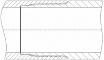
图1为公螺纹的结构示意图。Figure 1 is a schematic diagram of the structure of a male thread.
图2为母螺纹的结构示意图。Figure 2 is a schematic diagram of the structure of the female thread.
图3为公母螺纹配合的示意图。Fig. 3 is a schematic diagram of the mating of male and female threads.
具体实施方式:detailed description:
如图1、图2、图3所示,一种带限位台肩的气密封螺纹,包括设置在公接头1的公螺纹和设置在母接头4上的母螺纹;所述公螺纹底部的公接头1上设置有限位台肩2,公螺纹顶部的公接头1外壁上设置有锥形金属密封面Ⅰ3,母螺纹底部的母接头4内壁上设置有锥形金属密封面Ⅱ5,在上述公螺纹与上述母螺纹拧紧至母接头4端面与公接头1的限位台肩2完全贴合时,公螺纹与母螺纹达到螺纹最佳上紧扭矩位置,同时锥形金属密封面Ⅰ3与锥形金属密封面Ⅱ5完成配合形成金属密封。As shown in Figure 1, Figure 2, and Figure 3, an air-tight thread with a limit shoulder includes a male thread set on the
锥形金属密封面Ⅰ3的坡度为10~15°。The slope of the conical metal sealing surface I3 is 10-15°.
本发明的金属密封采用小角度锥面密封,相比现有气密封螺纹尖角接触式金属密封做封时产生应力集中小,且轴向偏差包容度高。本发明螺纹在API螺纹技术上优化设计,在上紧状态本身即可形成密封,安装时,拧紧至母螺纹端面与公螺纹限位台肩2完全贴合,即达到螺纹最佳上紧扭矩位置,可保证连接可靠并完成螺纹密封。同时,该安装位置下公螺纹顶部锥形金属密封面Ⅰ3与母螺纹底部锥形金属密封面Ⅱ5完成配合,可激发端部金属密封,完成二次密封。The metal seal of the present invention adopts a small-angle conical surface seal, and compared with the existing air-tight thread sharp-angle contact metal seal, the stress concentration is small, and the axial deviation tolerance is high. The thread of the present invention is optimized in API thread technology, and can form a seal in the tightened state. When installing, tighten until the end surface of the female thread and the
可以理解的是,以上关于本发明的具体描述,仅用于说明本发明而并非受限于本发明实施例所描述的技术方案,本领域的普通技术人员应当理解,仍然可以对本发明进行修改或等同替换,以达到相同的技术效果;只要满足使用需要,都在本发明的保护范围之内。It can be understood that the above specific descriptions of the present invention are only used to illustrate the present invention and are not limited to the technical solutions described in the embodiments of the present invention. Those of ordinary skill in the art should understand that the present invention can still be modified or Equivalent replacements to achieve the same technical effect; as long as they meet the needs of use, they are all within the protection scope of the present invention.
Claims (2)
Priority Applications (1)
| Application Number | Priority Date | Filing Date | Title |
|---|---|---|---|
| CN202110636006.8A CN115450569A (en) | 2021-06-08 | 2021-06-08 | Airtight seal thread with limiting shoulder |
Applications Claiming Priority (1)
| Application Number | Priority Date | Filing Date | Title |
|---|---|---|---|
| CN202110636006.8A CN115450569A (en) | 2021-06-08 | 2021-06-08 | Airtight seal thread with limiting shoulder |
Publications (1)
| Publication Number | Publication Date |
|---|---|
| CN115450569A true CN115450569A (en) | 2022-12-09 |
Family
ID=84294665
Family Applications (1)
| Application Number | Title | Priority Date | Filing Date |
|---|---|---|---|
| CN202110636006.8A Pending CN115450569A (en) | 2021-06-08 | 2021-06-08 | Airtight seal thread with limiting shoulder |
Country Status (1)
| Country | Link |
|---|---|
| CN (1) | CN115450569A (en) |
Cited By (1)
| Publication number | Priority date | Publication date | Assignee | Title |
|---|---|---|---|---|
| CN116557651A (en) * | 2023-05-16 | 2023-08-08 | 武汉市飞托克实业有限公司 | A compression joint with reduced and stable installation torque |
Citations (6)
| Publication number | Priority date | Publication date | Assignee | Title |
|---|---|---|---|---|
| CN201474625U (en) * | 2009-08-20 | 2010-05-19 | 宝山钢铁股份有限公司 | An ultra-high torsion-resistant metal hermetic drill pipe joint |
| WO2016064368A1 (en) * | 2014-10-23 | 2016-04-28 | Ооо "Интерпайп Менеджмент" | Sealed threaded joint for metal pipes |
| US20160230909A1 (en) * | 2013-03-21 | 2016-08-11 | Baoshan Iron & Steel Co., Ltd. | Superhigh torsional strength, metallic and airtight drillrod coupler |
| CN107503694A (en) * | 2016-06-14 | 2017-12-22 | 宝山钢铁股份有限公司 | A kind of two-stage seals nipple |
| CN108798550A (en) * | 2018-07-23 | 2018-11-13 | 中国石油天然气集团公司管材研究所 | A kind of titanium alloy oil pipe anti-galling air-tight seal screw joint |
| CN208220659U (en) * | 2018-05-18 | 2018-12-11 | 海隆石油钻具(无锡)有限公司 | A kind of hermetic sealing drill pipe joint |
-
2021
- 2021-06-08 CN CN202110636006.8A patent/CN115450569A/en active Pending
Patent Citations (6)
| Publication number | Priority date | Publication date | Assignee | Title |
|---|---|---|---|---|
| CN201474625U (en) * | 2009-08-20 | 2010-05-19 | 宝山钢铁股份有限公司 | An ultra-high torsion-resistant metal hermetic drill pipe joint |
| US20160230909A1 (en) * | 2013-03-21 | 2016-08-11 | Baoshan Iron & Steel Co., Ltd. | Superhigh torsional strength, metallic and airtight drillrod coupler |
| WO2016064368A1 (en) * | 2014-10-23 | 2016-04-28 | Ооо "Интерпайп Менеджмент" | Sealed threaded joint for metal pipes |
| CN107503694A (en) * | 2016-06-14 | 2017-12-22 | 宝山钢铁股份有限公司 | A kind of two-stage seals nipple |
| CN208220659U (en) * | 2018-05-18 | 2018-12-11 | 海隆石油钻具(无锡)有限公司 | A kind of hermetic sealing drill pipe joint |
| CN108798550A (en) * | 2018-07-23 | 2018-11-13 | 中国石油天然气集团公司管材研究所 | A kind of titanium alloy oil pipe anti-galling air-tight seal screw joint |
Cited By (1)
| Publication number | Priority date | Publication date | Assignee | Title |
|---|---|---|---|---|
| CN116557651A (en) * | 2023-05-16 | 2023-08-08 | 武汉市飞托克实业有限公司 | A compression joint with reduced and stable installation torque |
Similar Documents
| Publication | Publication Date | Title |
|---|---|---|
| CN201884831U (en) | Joint structure of two-way sealing pipe | |
| CN203531777U (en) | High-quality airtight seal oil casing threaded joint | |
| CN202380985U (en) | Tubular air seal thread joint | |
| CN201723179U (en) | Air-tight oil casing nipple | |
| CN208311717U (en) | Multi-sealed flange assembly | |
| CN203239244U (en) | Air-tight seal oil pipe screwed joint | |
| CN205938255U (en) | Take threaded connection structure of coating steel pipe with anti - corrosion feature | |
| CN206943645U (en) | A kind of quick pipe jointing | |
| CN202081837U (en) | Stress-resistant threaded connector with corrosive gas sealing sleeve | |
| CN208220659U (en) | A kind of hermetic sealing drill pipe joint | |
| CN209309502U (en) | A kind of pipeline hermetic seal threaded connection structure | |
| CN221053636U (en) | A high torque-resistant sealing joint for petroleum casing | |
| CN209164851U (en) | a quick connector | |
| CN208107197U (en) | A kind of gas sealing valve | |
| CN206268660U (en) | Tongue and groove vacuum flange | |
| CN205504019U (en) | External pressure bellows control valve | |
| CN102996079A (en) | Tubular air sealing screwed joint and application thereof | |
| CN106287044A (en) | There is the screw connection structure of the band coating steel pipe of corrosion proof function | |
| CN210089918U (en) | Integral adjustable direction conversion joint for taper thread pressure gauge | |
| CN205639973U (en) | Joint | |
| CN209654790U (en) | A kind of adjustable ground liner pipeline union connectors | |
| CN202645463U (en) | Thread gluing resistant two-stage gas seal screwed joint | |
| CN221958343U (en) | Novel VDA ball valve adapter | |
| CN213177213U (en) | Hard seal corrugated pipe structure | |
| CN206738761U (en) | A kind of high-temperature and pressure pipeline attachment structure with lining |
Legal Events
| Date | Code | Title | Description |
|---|---|---|---|
| PB01 | Publication | ||
| PB01 | Publication | ||
| SE01 | Entry into force of request for substantive examination | ||
| SE01 | Entry into force of request for substantive examination | ||
| RJ01 | Rejection of invention patent application after publication | ||
| RJ01 | Rejection of invention patent application after publication |
Application publication date: 20221209 |