CN115431083A - A pneumatic chuck - Google Patents
A pneumatic chuck Download PDFInfo
- Publication number
- CN115431083A CN115431083A CN202211221448.7A CN202211221448A CN115431083A CN 115431083 A CN115431083 A CN 115431083A CN 202211221448 A CN202211221448 A CN 202211221448A CN 115431083 A CN115431083 A CN 115431083A
- Authority
- CN
- China
- Prior art keywords
- cylinder
- driving
- base
- fixed
- driving arm
- Prior art date
- Legal status (The legal status is an assumption and is not a legal conclusion. Google has not performed a legal analysis and makes no representation as to the accuracy of the status listed.)
- Pending
Links
Images

Classifications
-
- B—PERFORMING OPERATIONS; TRANSPORTING
- B23—MACHINE TOOLS; METAL-WORKING NOT OTHERWISE PROVIDED FOR
- B23Q—DETAILS, COMPONENTS, OR ACCESSORIES FOR MACHINE TOOLS, e.g. ARRANGEMENTS FOR COPYING OR CONTROLLING; MACHINE TOOLS IN GENERAL CHARACTERISED BY THE CONSTRUCTION OF PARTICULAR DETAILS OR COMPONENTS; COMBINATIONS OR ASSOCIATIONS OF METAL-WORKING MACHINES, NOT DIRECTED TO A PARTICULAR RESULT
- B23Q3/00—Devices holding, supporting, or positioning work or tools, of a kind normally removable from the machine
- B23Q3/12—Devices holding, supporting, or positioning work or tools, of a kind normally removable from the machine for securing to a spindle in general
Landscapes
- Engineering & Computer Science (AREA)
- Mechanical Engineering (AREA)
- Jigs For Machine Tools (AREA)
Abstract
本发明涉及圆模木板加工设备技术领域,具体说,涉及一种气动卡盘夹。包括底座、气缸架、驱动气缸、驱动臂、连接块、动轮;所述底座包括圆柱体和固定在圆柱体一端的固定盘;所述气缸架固定在底座的固定盘上,所述驱动气缸的缸体固定在气缸架上;所述动轮套在底座的圆柱体上;所述动轮的外壁中部通过销轴与连接块的一端相连接;所述连接块的另一端通过销轴连接驱动臂的顶端;所述驱动臂上部通过销轴连接在底座的圆柱体上;所述驱动臂的下端连接在驱动气缸的活塞杆前端上。本发明所述气动卡盘夹能替代用人工松紧螺丝的传统方式,需要换工件的时候,通过控制驱动气缸,就能实现圆模支撑盘的夹紧与松开,更加省时省力,大大提高生产效率。
The invention relates to the technical field of round formwork wood board processing equipment, in particular to a pneumatic chuck clamp. It includes a base, a cylinder frame, a driving cylinder, a driving arm, a connecting block, and a moving wheel; the base includes a cylinder and a fixed plate fixed at one end of the cylinder; the cylinder frame is fixed on the fixed plate of the base, and the drive cylinder The cylinder block is fixed on the cylinder frame; the moving wheel is sleeved on the cylinder of the base; the middle part of the outer wall of the moving wheel is connected with one end of the connecting block through a pin; the other end of the connecting block is connected with the end of the driving arm through a pin The top; the upper part of the driving arm is connected to the cylinder of the base through a pin; the lower end of the driving arm is connected to the front end of the piston rod of the driving cylinder. The pneumatic chuck clamp of the present invention can replace the traditional way of using manual loosening screws. When the workpiece needs to be changed, the clamping and loosening of the round mold support plate can be realized by controlling the driving cylinder, which saves time and effort and greatly improves Productivity.
Description
技术领域technical field
本发明涉及圆模木板加工设备技术领域,具体地说,涉及一种气动卡盘夹。The invention relates to the technical field of round formwork wood board processing equipment, in particular to a pneumatic chuck clamp.
背景技术Background technique
在做包装盒时,为了精确地做出一些特别形状的东西,需要先做出刀版线,刀版线是加工在圆模上,而圆模是用圆模支撑盘固定在机床上。现有技术中,每加工完一个圆模板,更换工件的时候,要用扳手逐个地拧紧与松开各个螺丝来完成装卸工件,从而使圆模支撑盘得到固定,这种方式极其地费时费力,也大大降低了生产效率。When making packaging boxes, in order to accurately make some special shapes, it is necessary to make a cutting line first. The cutting line is processed on a round die, and the round die is fixed on the machine tool with a round die support plate. In the prior art, every time a round template is processed, when replacing the workpiece, it is necessary to use a wrench to tighten and loosen each screw one by one to complete the loading and unloading of the workpiece, so that the round mold support plate is fixed. This method is extremely time-consuming and laborious. Also greatly reduced production efficiency.
发明内容Contents of the invention
本发明的目的在于,提供一种气动卡盘夹,以解决上述的技术问题。The purpose of the present invention is to provide a pneumatic chuck clamp to solve the above technical problems.
为解决上述问题,本发明所采用的技术方案是:In order to solve the above problems, the technical solution adopted in the present invention is:
一种气动卡盘夹,其特征在于:包括底座、气缸架、驱动气缸、驱动臂、连接块、动轮;所述底座包括圆柱体和固定在圆柱体一端的固定盘;所述气缸架固定在底座的固定盘上,所述驱动气缸的缸体固定在气缸架上;所述动轮呈环状结构,套在底座的圆柱体上,其中部向下的部位厚度递减形成斜面状;所述动轮的外壁中部通过销轴与连接块的一端相连接;所述连接块的另一端通过销轴连接驱动臂的顶端;所述驱动臂上部通过销轴连接在底座的圆柱体上;所述驱动臂的下端连接在驱动气缸的活塞杆前端上。A pneumatic chuck clamp is characterized in that it includes a base, a cylinder frame, a driving cylinder, a driving arm, a connecting block, and a moving wheel; the base includes a cylinder and a fixed plate fixed at one end of the cylinder; the cylinder frame is fixed on On the fixed plate of the base, the cylinder body of the driving cylinder is fixed on the cylinder frame; the moving wheel is in a ring structure, which is sleeved on the cylinder of the base, and the thickness of the part downwards in the middle is gradually reduced to form an inclined plane; the moving wheel The middle part of the outer wall is connected to one end of the connecting block through a pin; the other end of the connecting block is connected to the top of the driving arm through a pin; the upper part of the driving arm is connected to the cylinder of the base through a pin; the driving arm The lower end is connected to the front end of the piston rod of the drive cylinder.
进一步地说:所述驱动臂的下端设有长条孔,该长条孔装配在所述活塞杆前端上的连接轴上。Further speaking: the lower end of the driving arm is provided with a long hole, and the long hole is assembled on the connecting shaft on the front end of the piston rod.
有益效果:与现有技术相比,本发明所述的气动卡盘夹能替代用人工松紧螺丝的传统方式,需要换工件的时候,通过控制驱动气缸,就能实现圆模支撑盘的夹紧与松开,更加省时省力,大大提高生产效率,具有良好的应用前景。Beneficial effects: Compared with the prior art, the pneumatic chuck clamp described in the present invention can replace the traditional way of using manual loose screws, and when the workpiece needs to be changed, the clamping of the round mold support plate can be realized by controlling the driving cylinder It saves time and effort, greatly improves production efficiency, and has a good application prospect.
附图说明Description of drawings
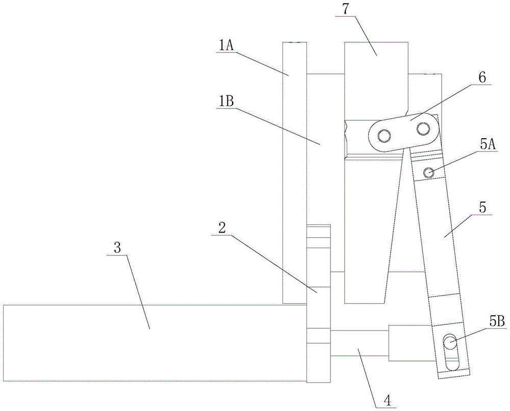
图1为本发明一种实施例的结构示意图。Fig. 1 is a schematic structural diagram of an embodiment of the present invention.
具体实施方式detailed description
下面结合附图和具体实施方式对本发明作进一步说明。The present invention will be further described below in conjunction with the accompanying drawings and specific embodiments.
实施例:Example:
参照图1,本实施例所述的气动卡盘夹,包括底座、气缸架2、驱动气缸3、驱动臂5、连接块6、动轮7。所述底座包括圆柱体1B和固定在圆柱体1B一端的固定盘1A;所述气缸架2固定在底座的固定盘1A上,所述驱动气缸3的缸体固定在气缸架2上;所述动轮7呈环状结构,套在底座的圆柱体1B上,其中部向下的部位厚度递减形成斜面状。所述动轮7的外壁中部通过销轴与连接块6的一端相连接;所述连接块6的另一端通过销轴连接驱动臂5的顶端;所述驱动臂5上部通过销轴5A连接在底座的圆柱体1B上。所述驱动臂5的下端连接在驱动气缸3的活塞杆4前端上,具体地说,所述驱动臂5的下端设有长条孔,该长条孔装配在所述活塞杆4前端上的连接轴5B上。Referring to FIG. 1 , the pneumatic chuck clip described in this embodiment includes a base, a
为避免动轮7在圆柱体1B上移动时跑偏,所述驱动臂5可以对称设置两个,分别位于动轮7的两侧,两个驱动臂5的顶端分别通过连接块与动轮7相连接,这样可以。当然,也可以将驱动臂5设计为U型结构,两个顶端分别通过连接块与动轮7相连接,两个支臂的下部分别通过设置长条孔,并装配在所述活塞杆4前端两侧的连接轴5B上。In order to prevent the moving
本发明所述的气动卡盘夹能替代用人工松紧螺丝的传统方式,具体使用时,将底座固定在机床主轴上,气缸架2通过螺丝紧定在底座的固定盘1A上,驱动气缸3固定装在气缸架2上,用驱动气缸3通过往复抽拉驱动臂5进行圆模支撑盘的夹紧和松开。因而,需要换工件的时候,轻轻一按控制驱动气缸的按钮,就能实现圆模支撑盘的夹紧与松开,更加省时省力,大大提高生产效率。The pneumatic chuck clamp described in the present invention can replace the traditional method of using manual elastic screws. When in use, the base is fixed on the main shaft of the machine tool, the
以上仅为本发明的实施方式,并非因此限制本发明的专利范围,凡是利用本发明说明书及附图内容所作的等效结构,直接或间接运用在其他相关的技术领域,均同理在本发明的专利保护范围之内。The above are only embodiments of the present invention, and are not intended to limit the patent scope of the present invention. All equivalent structures made using the description of the present invention and the contents of the accompanying drawings are directly or indirectly used in other related technical fields, and are equally applicable to the present invention. within the scope of patent protection.
Claims (2)
Applications Claiming Priority (2)
| Application Number | Priority Date | Filing Date | Title |
|---|---|---|---|
| CN2022222410361 | 2022-08-25 | ||
| CN202222241036 | 2022-08-25 |
Publications (1)
| Publication Number | Publication Date |
|---|---|
| CN115431083A true CN115431083A (en) | 2022-12-06 |
Family
ID=84251154
Family Applications (2)
| Application Number | Title | Priority Date | Filing Date |
|---|---|---|---|
| CN202222638771.6U Active CN218081626U (en) | 2022-08-25 | 2022-10-08 | Pneumatic chuck clamp |
| CN202211221448.7A Pending CN115431083A (en) | 2022-08-25 | 2022-10-08 | A pneumatic chuck |
Family Applications Before (1)
| Application Number | Title | Priority Date | Filing Date |
|---|---|---|---|
| CN202222638771.6U Active CN218081626U (en) | 2022-08-25 | 2022-10-08 | Pneumatic chuck clamp |
Country Status (1)
| Country | Link |
|---|---|
| CN (2) | CN218081626U (en) |
Families Citing this family (1)
| Publication number | Priority date | Publication date | Assignee | Title |
|---|---|---|---|---|
| CN218081626U (en) * | 2022-08-25 | 2022-12-20 | 高唐县浩泽数控设备有限公司 | Pneumatic chuck clamp |
Citations (5)
| Publication number | Priority date | Publication date | Assignee | Title |
|---|---|---|---|---|
| CN203566273U (en) * | 2013-11-27 | 2014-04-30 | Smc(中国)有限公司 | Short-stroked clamping cylinder |
| CN107932130A (en) * | 2017-10-16 | 2018-04-20 | 浙江美登特种薄膜有限公司 | A kind of clamping device with self-centering function |
| CN207735974U (en) * | 2018-01-08 | 2018-08-17 | 佛山市南海瀚坤堂精密五金制品有限公司 | Machining clamp for numerical control machine |
| CN109047615A (en) * | 2018-06-22 | 2018-12-21 | 青岛大学 | A kind of forging machinery arm clamper being suitable for various outer diameter size cylindrical workpiece |
| CN218081626U (en) * | 2022-08-25 | 2022-12-20 | 高唐县浩泽数控设备有限公司 | Pneumatic chuck clamp |
-
2022
- 2022-10-08 CN CN202222638771.6U patent/CN218081626U/en active Active
- 2022-10-08 CN CN202211221448.7A patent/CN115431083A/en active Pending
Patent Citations (5)
| Publication number | Priority date | Publication date | Assignee | Title |
|---|---|---|---|---|
| CN203566273U (en) * | 2013-11-27 | 2014-04-30 | Smc(中国)有限公司 | Short-stroked clamping cylinder |
| CN107932130A (en) * | 2017-10-16 | 2018-04-20 | 浙江美登特种薄膜有限公司 | A kind of clamping device with self-centering function |
| CN207735974U (en) * | 2018-01-08 | 2018-08-17 | 佛山市南海瀚坤堂精密五金制品有限公司 | Machining clamp for numerical control machine |
| CN109047615A (en) * | 2018-06-22 | 2018-12-21 | 青岛大学 | A kind of forging machinery arm clamper being suitable for various outer diameter size cylindrical workpiece |
| CN218081626U (en) * | 2022-08-25 | 2022-12-20 | 高唐县浩泽数控设备有限公司 | Pneumatic chuck clamp |
Also Published As
| Publication number | Publication date |
|---|---|
| CN218081626U (en) | 2022-12-20 |
Similar Documents
| Publication | Publication Date | Title |
|---|---|---|
| CN108296829A (en) | A kind of fixture for the processing of automobile air conditioner compressor rear cover | |
| CN109605092A (en) | A kind of General hydraulic quick clamping tool | |
| CN207272791U (en) | A middle plate clamping jig with suction function | |
| CN206393070U (en) | A kind of fixture for laser welding | |
| CN209614919U (en) | A multi-station precision pneumatic tooling fixture for CNC machining of fine steel products | |
| CN218081626U (en) | Pneumatic chuck clamp | |
| CN217596546U (en) | Automobile swing arm machining clamp | |
| CN205636048U (en) | A frame is fixed to template for on full -automatic template sewing machine | |
| CN205668158U (en) | The Quick-clamped positioning fixture of turbocharger housing | |
| CN206632682U (en) | One kind combination clamping device | |
| CN218696256U (en) | Car sheet metal component positioning fixture | |
| CN203266457U (en) | Hydraulic flat tongs | |
| CN211386862U (en) | A high-strength and fast gripper | |
| CN221774020U (en) | A new type of pneumatic chuck clamp | |
| CN204366549U (en) | Hydraulic engine cylinder body clamp for milling end surfaces | |
| CN214135673U (en) | An easy-to-operate fixture | |
| CN223572929U (en) | Multifunctional combined jig with replaceable inner core | |
| CN219379902U (en) | Novel tool clamp for concave-shaped workpiece | |
| CN105058081B (en) | The many planes of heavy castings porous are with orientation finishing fixture | |
| CN206215959U (en) | A kind of ring flange perforating device of cast iron valve | |
| CN222327452U (en) | Three-head free switching efficient engraving tool | |
| CN221539003U (en) | Pneumatic tool for aluminum ring lock sleeve in lifting rod | |
| CN218396968U (en) | Double-station clamp for machining single needle side seat | |
| CN215588506U (en) | Hinged device pin shaft drilling fast loading and unloading device for construction machinery | |
| CN221696118U (en) | Pressing plate tool |
Legal Events
| Date | Code | Title | Description |
|---|---|---|---|
| PB01 | Publication | ||
| PB01 | Publication | ||
| SE01 | Entry into force of request for substantive examination | ||
| SE01 | Entry into force of request for substantive examination |