CN115419203A - Assembly type shear wall semi-dry type connection composite floor slab structure and construction method thereof - Google Patents
Assembly type shear wall semi-dry type connection composite floor slab structure and construction method thereof Download PDFInfo
- Publication number
- CN115419203A CN115419203A CN202210923666.9A CN202210923666A CN115419203A CN 115419203 A CN115419203 A CN 115419203A CN 202210923666 A CN202210923666 A CN 202210923666A CN 115419203 A CN115419203 A CN 115419203A
- Authority
- CN
- China
- Prior art keywords
- floor slab
- shear wall
- floor
- laminated
- composite floor
- Prior art date
- Legal status (The legal status is an assumption and is not a legal conclusion. Google has not performed a legal analysis and makes no representation as to the accuracy of the status listed.)
- Pending
Links
Images



Classifications
-
- E—FIXED CONSTRUCTIONS
- E04—BUILDING
- E04B—GENERAL BUILDING CONSTRUCTIONS; WALLS, e.g. PARTITIONS; ROOFS; FLOORS; CEILINGS; INSULATION OR OTHER PROTECTION OF BUILDINGS
- E04B5/00—Floors; Floor construction with regard to insulation; Connections specially adapted therefor
- E04B5/16—Load-carrying floor structures wholly or partly cast or similarly formed in situ
- E04B5/32—Floor structures wholly cast in situ with or without form units or reinforcements
- E04B5/36—Floor structures wholly cast in situ with or without form units or reinforcements with form units as part of the floor
- E04B5/38—Floor structures wholly cast in situ with or without form units or reinforcements with form units as part of the floor with slab-shaped form units acting simultaneously as reinforcement; Form slabs with reinforcements extending laterally outside the element
-
- E—FIXED CONSTRUCTIONS
- E04—BUILDING
- E04B—GENERAL BUILDING CONSTRUCTIONS; WALLS, e.g. PARTITIONS; ROOFS; FLOORS; CEILINGS; INSULATION OR OTHER PROTECTION OF BUILDINGS
- E04B1/00—Constructions in general; Structures which are not restricted either to walls, e.g. partitions, or floors or ceilings or roofs
- E04B1/38—Connections for building structures in general
- E04B1/61—Connections for building structures in general of slab-shaped building elements with each other
- E04B1/6108—Connections for building structures in general of slab-shaped building elements with each other the frontal surfaces of the slabs connected together
- E04B1/6116—Connections for building structures in general of slab-shaped building elements with each other the frontal surfaces of the slabs connected together by locking means on lateral surfaces
-
- E—FIXED CONSTRUCTIONS
- E04—BUILDING
- E04C—STRUCTURAL ELEMENTS; BUILDING MATERIALS
- E04C2/00—Building elements of relatively thin form for the construction of parts of buildings, e.g. sheet materials, slabs, or panels
- E04C2/02—Building elements of relatively thin form for the construction of parts of buildings, e.g. sheet materials, slabs, or panels characterised by specified materials
- E04C2/04—Building elements of relatively thin form for the construction of parts of buildings, e.g. sheet materials, slabs, or panels characterised by specified materials of concrete or other stone-like material; of asbestos cement; of cement and other mineral fibres
- E04C2/06—Building elements of relatively thin form for the construction of parts of buildings, e.g. sheet materials, slabs, or panels characterised by specified materials of concrete or other stone-like material; of asbestos cement; of cement and other mineral fibres reinforced
-
- E—FIXED CONSTRUCTIONS
- E04—BUILDING
- E04C—STRUCTURAL ELEMENTS; BUILDING MATERIALS
- E04C5/00—Reinforcing elements, e.g. for concrete; Auxiliary elements therefor
- E04C5/01—Reinforcing elements of metal, e.g. with non-structural coatings
- E04C5/06—Reinforcing elements of metal, e.g. with non-structural coatings of high bending resistance, i.e. of essentially three-dimensional [3D] extent, e.g. lattice girders
- E04C5/065—Light-weight girders, e.g. with precast parts
- E04C5/0653—Light-weight girders, e.g. with precast parts with precast parts
- E04C5/0656—Light-weight girders, e.g. with precast parts with precast parts with lost formwork
-
- E—FIXED CONSTRUCTIONS
- E04—BUILDING
- E04B—GENERAL BUILDING CONSTRUCTIONS; WALLS, e.g. PARTITIONS; ROOFS; FLOORS; CEILINGS; INSULATION OR OTHER PROTECTION OF BUILDINGS
- E04B1/00—Constructions in general; Structures which are not restricted either to walls, e.g. partitions, or floors or ceilings or roofs
- E04B1/38—Connections for building structures in general
- E04B1/61—Connections for building structures in general of slab-shaped building elements with each other
- E04B2001/6195—Connections for building structures in general of slab-shaped building elements with each other the slabs being connected at an angle, e.g. forming a corner
-
- E—FIXED CONSTRUCTIONS
- E04—BUILDING
- E04B—GENERAL BUILDING CONSTRUCTIONS; WALLS, e.g. PARTITIONS; ROOFS; FLOORS; CEILINGS; INSULATION OR OTHER PROTECTION OF BUILDINGS
- E04B5/00—Floors; Floor construction with regard to insulation; Connections specially adapted therefor
- E04B5/16—Load-carrying floor structures wholly or partly cast or similarly formed in situ
- E04B5/32—Floor structures wholly cast in situ with or without form units or reinforcements
- E04B2005/324—Floor structures wholly cast in situ with or without form units or reinforcements with peripheral anchors or supports
Landscapes
- Engineering & Computer Science (AREA)
- Architecture (AREA)
- Civil Engineering (AREA)
- Structural Engineering (AREA)
- Physics & Mathematics (AREA)
- Electromagnetism (AREA)
- Bridges Or Land Bridges (AREA)
Abstract
本发明涉及一种装配式剪力墙半干式连接叠合楼板结构及其施工方法,包括顶层叠合楼板、底层地合楼板和装配式剪力墙的侧面均设置有伸出楼板筋,所述顶层叠合楼板和底层地合楼板分别与装配式剪力墙的顶部和底部搭接连接,使得其各自对应的伸出楼板钢筋相互交错;中间层叠合楼板的楼板筋端面与中间层叠合楼板侧面平齐或位于侧面内侧,所述中间层叠合楼板与装配式剪力墙的中部通过若干组装配组件连接,所述装配式剪力墙还预制有预留楼板筋,所述预留楼板筋横向伸出所述装配式剪力墙侧面,与中间层叠合楼板的楼板筋相互交错;方法包括将中间层叠合楼板和装配式剪力墙初步固定后,将预留楼板筋与所述中间层叠合楼板浇筑为一体结构。强度高,稳定性强。

The invention relates to a prefabricated shear wall semi-dry connection laminated floor structure and its construction method, including the top laminated floor, the bottom floor laminated floor and the sides of the prefabricated shear wall are all provided with protruding floor ribs, so that The top laminated floor and the ground floor laminated floor are lapped and connected to the top and bottom of the prefabricated shear wall respectively, so that their respective protruding floor reinforcements are staggered; The sides are flush or located on the inside of the side. The laminated floor of the middle layer is connected with the middle part of the prefabricated shear wall through several sets of assembly components. The prefabricated shear wall is also prefabricated with reserved floor reinforcement. extending laterally from the side of the prefabricated shear wall, interlaced with the floor reinforcement of the interlayer laminated floor; the method includes preliminarily fixing the interlayer laminated floor and the prefabricated shear wall, and then placing the reserved floor reinforcement on the interlayer The combined floor slab is poured into an integrated structure. High strength and strong stability.
Description
技术领域technical field
本发明涉及装配式混凝土剪力墙和叠合楼板连接施工技术领域,尤其涉及一种装配式剪力墙半干式连接叠合楼板结构及其施工方法。The invention relates to the technical field of connection construction of a prefabricated concrete shear wall and a laminated floor, in particular to a semi-dry connection laminated floor structure of a prefabricated shear wall and a construction method thereof.
背景技术Background technique
现有装配式剪力墙多采用一次预制单层墙体,在现场进行单层墙体以及叠合楼板组装的方案,但该方案现场工作量较多,未能充分体现装配式剪力墙结构自身优点。而如若采用一次预制双层墙体方案,可以极大的加快施工进度,减少现场工作量。但一次预制双层墙体方案使得装配式剪力墙中间层区域不再满足叠合楼板搭接连接方式的条件,可见现有的叠合楼板搭接连接方式并不适用于中间层叠合楼板与双层装配式剪力墙的连接。Existing prefabricated shear walls mostly use one-time prefabricated single-layer walls, and assemble single-layer walls and laminated floors on site. However, this scheme has a lot of on-site workload and fails to fully reflect the prefabricated shear wall structure. own advantages. However, if a prefabricated double-layer wall scheme is adopted, the construction progress can be greatly accelerated and the workload on site can be reduced. However, the one-time prefabricated double-layer wall scheme makes the middle layer area of the prefabricated shear wall no longer meet the conditions of the lap connection method of the laminated floor. It can be seen that the existing lap connection method of the laminated floor is not suitable for the laminated floor of the middle layer Connection of double-layer prefabricated shear walls.
发明内容Contents of the invention
鉴于上述现有技术中存在或潜在的不足之处,本发明提供了一种用于解决中间层叠合楼板与双层装配式剪力墙连接的装配式剪力墙半干式连接叠合楼板结构。In view of the above-mentioned existing or potential deficiencies in the prior art, the present invention provides a semi-dry connection laminated floor structure of a prefabricated shear wall used to solve the problem of connecting the middle layer laminated floor with a double-layer prefabricated shear wall .
为了达到以上目的,本发明采取以下技术方案:In order to achieve the above object, the present invention takes the following technical solutions:
一种装配式剪力墙半干式连接叠合楼板结构,包括装配式剪力墙、顶层叠合楼板、中间层叠合楼板和底层叠合楼板,所述顶层叠合楼板、底层地合楼板和装配式剪力墙的侧面均设置有伸出楼板筋,所述顶层叠合楼板和底层地合楼板分别与装配式剪力墙的顶部和底部搭接连接,使得其各自对应的伸出楼板钢筋相互交错;所述中间层叠合楼板的楼板筋端面与中间层叠合楼板侧面平齐或位于侧面内侧,所述中间层叠合楼板与装配式剪力墙的中部通过若干组装配组件连接,所述装配组件包括L形安装板、连接螺栓和螺母,所述中间层叠合楼板的边缘预制有竖向连接螺栓,所述装配式剪力墙预制有横向连接螺栓,所述L形安装板设置有配合所述竖向连接螺栓和横向螺栓的调节孔洞;所述装配式剪力墙还预制有预留楼板筋,所述预留楼板筋横向伸出所述装配式剪力墙侧面,与中间层叠合楼板的楼板筋相互交错;通过现场浇筑使得所述装配式剪力墙、顶层叠合楼板、中间层叠合楼板和底层叠合楼板连接呈一个整体。A prefabricated shear wall semi-dry connection laminated floor structure, including a prefabricated shear wall, a top laminated floor, an intermediate laminated floor and a bottom laminated floor, the top laminated floor, the ground laminated floor and The sides of the prefabricated shear wall are all provided with protruding floor reinforcements, and the top laminated floor and the bottom ground composite floor are respectively lapped and connected with the top and bottom of the prefabricated shear wall, so that their respective protruding floor reinforcements Interlaced with each other; the end face of the slab ribs of the interlayer laminated slab is flush with the side of the interlayer laminated slab or located on the inside of the side; The assembly includes an L-shaped mounting plate, connecting bolts and nuts. The edge of the interlayer laminated floor is prefabricated with vertical connecting bolts. The prefabricated shear wall is prefabricated with horizontal connecting bolts. The L-shaped mounting plate is provided with matching The adjustment holes for vertical connecting bolts and transverse bolts; the prefabricated shear wall is also prefabricated with reserved floor reinforcement, and the reserved floor reinforcement extends laterally out of the side of the assembly shear wall, and the floor is laminated with the middle layer The floor reinforcements are interlaced; the prefabricated shear wall, the top laminated floor, the middle laminated floor and the bottom laminated floor are connected as a whole through on-site pouring.
作为优选,所述中间层叠合楼板在其楼板筋端面对应的两端与所述装配式剪力墙连接,所述竖向连接螺栓设置在靠近对应两端的边缘。Preferably, the laminated floor slab of the middle layer is connected to the prefabricated shear wall at the two ends corresponding to the end faces of the slab reinforcement, and the vertical connecting bolts are arranged on the edges close to the corresponding two ends.
作为优选,所述竖向连接螺栓和横向螺栓分别与中间层叠合楼板和装配式剪力墙内部的楼板筋连接为一体结构。Preferably, the vertical connecting bolts and the transverse bolts are respectively connected with the interlayer laminated floor and the floor reinforcement inside the prefabricated shear wall to form an integral structure.
作为优选,所述装配式组件与预留楼板筋均设置在中间层叠合板的上侧;所述竖向螺栓从中间层叠合楼板的上表面伸出向上。Preferably, the prefabricated components and the reserved floor ribs are both arranged on the upper side of the laminated slab of the middle layer; the vertical bolts protrude upward from the upper surface of the laminated floor of the middle layer.
作为优选,每组所述装配组件对应一组预留楼板筋,每组预留楼板筋至少为一个,所述预留楼板筋与装配式剪力墙内部的楼板筋链接为一体结构。Preferably, each group of assembly components corresponds to a set of reserved floor reinforcements, each group of reserved floor reinforcements has at least one, and the reserved floor reinforcements are connected with the floor reinforcements inside the prefabricated shear wall to form an integrated structure.
作为优选,相邻两组所述装配组件之间的距离小于或等于800~900mm。Preferably, the distance between two adjacent groups of assembly components is less than or equal to 800-900 mm.
作为优选,所述预留楼板筋的长度大于或等于400~500mm,大于横向螺栓的长度。Preferably, the length of the reserved floor reinforcement is greater than or equal to 400-500mm, which is greater than the length of the transverse bolts.
作为优选,所述调节孔洞为长条形的孔,所述L形安装板为可调式角钢。Preferably, the adjustment hole is an elongated hole, and the L-shaped mounting plate is an adjustable angle steel.
有益效果:本发明解决了中间层叠合楼板与双层装配式剪力墙连接的技术问题;通过预制双层层高的装配式剪力墙和中间层叠合楼板,在装配式剪力墙和中间层叠合楼板上分别预制横向连接螺栓和竖向连接螺栓,所述装配式剪力墙和中间层叠合楼板还预制有与中间层叠合楼板上的楼板筋相互交错的预留楼板筋,然后通过L形安装板配合螺母将中间层叠合板初步固定,最后将预留楼板筋、装配式组件和中间层叠合楼板及其楼板筋浇筑为一体结构,完成最终连接固定;连接强度高,稳定性强,外观平整,无外露连接件,安全性高。Beneficial effects: the invention solves the technical problem of connecting the interlayer laminated floor with the double-layer prefabricated shear wall; through the prefabricated double-storey prefabricated shear wall and the interlayer laminated floor, the prefabricated shear wall and the intermediate The horizontal connecting bolts and vertical connecting bolts are respectively prefabricated on the layer laminated floor, and the prefabricated shear wall and the intermediate layer laminated floor are also prefabricated with reserved floor reinforcement interlaced with the floor reinforcement on the intermediate layer laminated floor, and then through L Shaped mounting plate and nuts are used to preliminarily fix the laminated slab in the middle layer, and finally the reserved floor reinforcement, prefabricated components, laminated floor slab and its floor reinforcement in the middle layer are poured into an integrated structure to complete the final connection and fixation; the connection strength is high, the stability is strong, and the appearance Flat, no exposed joints, high safety.
为了解决现有技术的不足,解决中间层叠合楼板与双层装配式剪力墙连接,本发明还提供了一种上述任一所述装配式剪力墙半干式连接叠合楼板结构的施工方法,方案如下:In order to solve the deficiencies of the prior art and to solve the connection between the middle layer laminated floor and the double-layer prefabricated shear wall, the present invention also provides a construction of the semi-dry connection laminated floor structure of any one of the above-mentioned prefabricated shear walls method, the scheme is as follows:
一种根据上述任一所述装配式剪力墙半干式连接叠合楼板结构的施工方法,所述装配式剪力墙的高度预制为两层层高;吊装所述中间层叠合楼板于规定位置,在横向螺栓和竖向螺栓对应位置布置所述L形安装板,调整所述中间层叠合楼板的水平和竖向位置;通过螺母配合连接横向螺栓和竖向螺栓将中间层叠合楼板固定在装配式剪力墙上;将预留楼板筋、装配式组件与所述中间层叠合楼板浇筑为一体结构,实现装配式剪力墙和所述中间层叠合楼板连接。A construction method according to any one of the above-mentioned prefabricated shear wall semi-dry connection laminated floor structures, the height of the prefabricated shear wall is prefabricated to two floors; position, the L-shaped mounting plate is arranged at the corresponding positions of the horizontal bolts and the vertical bolts, and the horizontal and vertical positions of the laminated floor of the middle layer are adjusted; the laminated floor of the middle layer is fixed on the Prefabricated shear wall: The reserved floor reinforcement, prefabricated components and the interlayer laminated floor are poured into an integrated structure to realize the connection between the prefabricated shear wall and the intermediary laminated floor.
有益效果:本发明中连接螺栓和螺母的可拆卸配合有利于中间层叠合楼板吊装安装时的调节,在将其与L形安装板、预留楼板筋和中间层叠合楼板浇筑为一体后,解决了螺栓螺母连接的不稳定性问题,和连接组件凸出及外露问题,同时还发挥了加强筋的功用。Beneficial effects: the detachable cooperation of the connecting bolts and nuts in the present invention is beneficial to the adjustment of the interlayer laminated floor slab hoisting and installation. It solves the instability problem of the bolt and nut connection, and the protruding and exposed problems of the connecting components, and also plays the role of the reinforcing rib.
附图说明Description of drawings
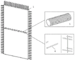
图1为本发明整体连接结构示意图;Fig. 1 is a schematic diagram of the overall connection structure of the present invention;
图2为装配式剪力墙的结构示意图;Fig. 2 is a structural schematic diagram of a prefabricated shear wall;
图3为中间层叠合楼板的结构示意图;Fig. 3 is the structural schematic diagram of interlayer laminated floor;
图4为装配组件的结构示意图;Fig. 4 is the structural representation of assembly assembly;
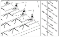
图5为中间层叠合楼板和装配式剪力墙的安装示意图一;Figure 5 is a schematic diagram of the installation of the interlayer laminated floor and the prefabricated shear wall;
图6为中间层叠合楼板和装配式剪力墙的安装示意图二;Fig. 6 is the installation schematic diagram 2 of the laminated floor slab of the middle layer and the prefabricated shear wall;
图7为中间层叠合楼板和装配式剪力墙的安装示意图三;Figure 7 is a schematic diagram of the installation of the middle layer laminated floor and the prefabricated shear wall;
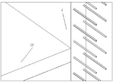
图8为中间层叠合楼板和装配式剪力墙现场浇筑混凝土后的结构示意图;Figure 8 is a structural schematic diagram of the interlayer laminated floor and the prefabricated shear wall after pouring concrete on site;
图中:装配式剪力墙1,顶层叠合楼板2,中间层叠合楼板3,底层叠合楼板4,连接螺栓5,预留楼板筋6,螺母7,调节孔洞8,安装板9,现浇楼板10。In the figure: prefabricated
具体实施方式Detailed ways
下面结合具体实施例和附图对本发明作进一步说明。The present invention will be further described below in combination with specific embodiments and accompanying drawings.
图1至图8出示了一种装配式剪力墙1半干式连接叠合楼板结构,包括装配式剪力墙1、顶层叠合楼板2、中间层叠合楼板3和底层叠合楼板4,所述顶层叠合楼板2、底层地合楼板和装配式剪力墙1的侧面均设置有伸出楼板筋,所述顶层叠合楼板2和底层地合楼板分别与装配式剪力墙1的顶部和底部搭接连接,使得其各自对应的伸出楼板钢筋相互交错;所述中间层叠合楼板3的楼板筋端面与中间层叠合楼板3侧面平齐或位于侧面内侧,所述中间层叠合楼板3与装配式剪力墙1的中部通过若干组装配组件连接,所述装配组件包括L形安装板9、连接螺栓5和螺母7,所述中间层叠合楼板3的边缘预制有竖向连接螺栓5,所述装配式剪力墙1预制有横向连接螺栓5,所述L形安装板9设置有配合所述竖向连接螺栓5和横向螺栓的调节孔洞8;所述装配式剪力墙1还预制有预留楼板筋6,所述预留楼板筋6横向伸出所述装配式剪力墙1侧面,与中间层叠合楼板3的楼板筋相互交错;通过现场浇筑使得所述装配式剪力墙1、顶层叠合楼板2、中间层叠合楼板3和底层叠合楼板4连接呈一个整体,如图8所示。Figures 1 to 8 show a
作为优选的另一实施例中,所述中间层叠合楼板3在其楼板筋端面对应的两端与所述装配式剪力墙1连接,所述竖向连接螺栓5设置在靠近对应两端的边缘。As another preferred embodiment, the interlayer laminated
作为优选的另一实施例中,所述竖向连接螺栓5和横向螺栓分别与中间层叠合楼板3和装配式剪力墙1内部的楼板筋连接为一体结构。As another preferred embodiment, the vertical connecting
作为优选的另一实施例中,所述装配式组件与预留楼板筋6均设置在中间层叠合板的上侧;所述竖向螺栓从中间层叠合楼板3的上表面伸出向上As another preferred embodiment, the prefabricated components and the
作为优选的另一实施例中,每组所述装配组件对应一组预留楼板筋6,每组预留楼板筋6至少为一个,所述预留楼板筋6与装配式剪力墙1内部的楼板筋链接为一体结构。As another preferred embodiment, each group of assembly components corresponds to a set of
作为优选的另一实施例中,相邻两组所述装配组件之间的距离小于或等于800~900mm。As another preferred embodiment, the distance between two adjacent groups of assembly components is less than or equal to 800-900 mm.
作为优选的另一实施例中,所述预留楼板筋6的长度大于或等于400~500mm,大于横向螺栓的长度。As another preferred embodiment, the length of the
作为优选的另一实施例中,所述调节孔洞8为长条形的孔,所述L形安装板9为可调式角钢。As another preferred embodiment, the
本发明解决了中间层叠合楼板3与双层装配式剪力墙1连接的技术问题;通过预制双层层高的装配式剪力墙1和中间层叠合楼板3,在装配式剪力墙1和中间层叠合楼板3上分别预制横向连接螺栓5和竖向连接螺栓5,所述装配式剪力墙1和中间层叠合楼板3还预制有与中间层叠合楼板3上的楼板筋相互交错的预留楼板筋6,然后通过L形安装板9配合螺母7将中间层叠合板初步固定,最后将预留楼板筋6、装配式组件和中间层叠合楼板3及其楼板筋浇筑为一体结构的现浇楼板10,完成最终连接固定;连接强度高,稳定性强,外观平整,无外露连接件,安全性高。The present invention solves the technical problem of connecting the middle layer laminated
为了解决现有技术的不足,解决中间层叠合楼板3与双层装配式剪力墙1连接,本发明还提供了一种上述任一所述装配式剪力墙1半干式连接叠合楼板结构的施工方法,实施方式如下:In order to solve the deficiencies of the prior art and to solve the connection between the middle layer laminated
一种根据上述任一所述装配式剪力墙1半干式连接叠合楼板结构的施工方法,所述装配式剪力墙1的高度预制为两层层高;吊装所述中间层叠合楼板3于规定位置,在横向螺栓和竖向螺栓对应位置布置所述L形安装板9,调整所述中间层叠合楼板3的水平和竖向位置;通过螺母7配合连接横向螺栓和竖向螺栓将中间层叠合楼板3固定在装配式剪力墙1上;将预留楼板筋6、装配式组件与所述中间层叠合楼板3浇筑为一体结构,实现装配式剪力墙1和所述中间层叠合楼板3连接。A construction method according to any one of the above-mentioned
本实施例中的方法包括将中间层叠合楼板3和装配式剪力墙1初步固定后,将预留楼板筋6与所述中间层叠合楼板3浇筑为一体结构;连接螺栓5和螺母7的可拆卸配合有利于中间层叠合楼板3吊装安装时的调节,在将其与L形安装板9、预留楼板筋6和中间层叠合楼板3浇筑为一体后,解决了螺栓螺母7连接的不稳定性问题,和连接组件凸出及外露问题,同时还发挥了加强筋的功用。The method in this embodiment includes preliminarily fixing the interlayer laminated
最后应说明的是:以上实施例仅用以说明本发明的技术方案,而非对其限制;尽管参照前述实施例对本发明进行了详细的说明,本领域的普通技术人员应当理解:其依然可以对前述各实施例所记载的技术方案进行修改,或者对其中部分技术特征进行等同替换;而这些修改或者替换,并不使相应技术方案的本质脱离本发明各实施例技术方案的范围。Finally, it should be noted that: the above embodiments are only used to illustrate the technical solutions of the present invention, rather than to limit them; although the present invention has been described in detail with reference to the foregoing embodiments, those of ordinary skill in the art should understand that: it can still be Modifications are made to the technical solutions described in the foregoing embodiments, or equivalent replacements are made to some of the technical features; and these modifications or replacements do not make the essence of the corresponding technical solutions depart from the scope of the technical solutions of the embodiments of the present invention.
Claims (9)
Priority Applications (1)
| Application Number | Priority Date | Filing Date | Title |
|---|---|---|---|
| CN202210923666.9A CN115419203A (en) | 2022-08-02 | 2022-08-02 | Assembly type shear wall semi-dry type connection composite floor slab structure and construction method thereof |
Applications Claiming Priority (1)
| Application Number | Priority Date | Filing Date | Title |
|---|---|---|---|
| CN202210923666.9A CN115419203A (en) | 2022-08-02 | 2022-08-02 | Assembly type shear wall semi-dry type connection composite floor slab structure and construction method thereof |
Publications (1)
| Publication Number | Publication Date |
|---|---|
| CN115419203A true CN115419203A (en) | 2022-12-02 |
Family
ID=84195889
Family Applications (1)
| Application Number | Title | Priority Date | Filing Date |
|---|---|---|---|
| CN202210923666.9A Pending CN115419203A (en) | 2022-08-02 | 2022-08-02 | Assembly type shear wall semi-dry type connection composite floor slab structure and construction method thereof |
Country Status (1)
| Country | Link |
|---|---|
| CN (1) | CN115419203A (en) |
Cited By (1)
| Publication number | Priority date | Publication date | Assignee | Title |
|---|---|---|---|---|
| CN116771132A (en) * | 2023-07-06 | 2023-09-19 | 中国建筑第五工程局有限公司 | Construction method for connecting structure of prefabricated multilayer combined shear wall and local superimposed sheet |
Citations (7)
| Publication number | Priority date | Publication date | Assignee | Title |
|---|---|---|---|---|
| CN205189168U (en) * | 2015-11-30 | 2016-04-27 | 中国建筑第七工程局有限公司 | Assembled shear wall structure system |
| CN205954838U (en) * | 2016-08-30 | 2017-02-15 | 山东莱钢建设有限公司 | Assembly type structure thing |
| CN206607709U (en) * | 2017-04-13 | 2017-11-03 | 安徽富煌建筑设计研究有限公司 | A kind of assembling type steel structure external hanging type wallboard base-supporting attachment structure |
| CN108252420A (en) * | 2017-12-19 | 2018-07-06 | 浙江绿筑集成科技有限公司 | A kind of connection method of no support type laminated floor slab and PEC shear walls |
| WO2019056717A1 (en) * | 2017-09-21 | 2019-03-28 | 中国建筑股份有限公司 | Post-tensioned prestressed assembly-style system of concrete framework and shock-resistant and energy-dissipating components, and construction method |
| CN109555252A (en) * | 2019-01-21 | 2019-04-02 | 沈阳建筑大学 | The floor and shear wall structure of overhanging rectangle muscle and connection method |
| CN209293238U (en) * | 2018-12-13 | 2019-08-23 | 美好建筑装配科技有限公司 | Section overlap joint connection is poured after overlapped shear wall |
-
2022
- 2022-08-02 CN CN202210923666.9A patent/CN115419203A/en active Pending
Patent Citations (7)
| Publication number | Priority date | Publication date | Assignee | Title |
|---|---|---|---|---|
| CN205189168U (en) * | 2015-11-30 | 2016-04-27 | 中国建筑第七工程局有限公司 | Assembled shear wall structure system |
| CN205954838U (en) * | 2016-08-30 | 2017-02-15 | 山东莱钢建设有限公司 | Assembly type structure thing |
| CN206607709U (en) * | 2017-04-13 | 2017-11-03 | 安徽富煌建筑设计研究有限公司 | A kind of assembling type steel structure external hanging type wallboard base-supporting attachment structure |
| WO2019056717A1 (en) * | 2017-09-21 | 2019-03-28 | 中国建筑股份有限公司 | Post-tensioned prestressed assembly-style system of concrete framework and shock-resistant and energy-dissipating components, and construction method |
| CN108252420A (en) * | 2017-12-19 | 2018-07-06 | 浙江绿筑集成科技有限公司 | A kind of connection method of no support type laminated floor slab and PEC shear walls |
| CN209293238U (en) * | 2018-12-13 | 2019-08-23 | 美好建筑装配科技有限公司 | Section overlap joint connection is poured after overlapped shear wall |
| CN109555252A (en) * | 2019-01-21 | 2019-04-02 | 沈阳建筑大学 | The floor and shear wall structure of overhanging rectangle muscle and connection method |
Cited By (1)
| Publication number | Priority date | Publication date | Assignee | Title |
|---|---|---|---|---|
| CN116771132A (en) * | 2023-07-06 | 2023-09-19 | 中国建筑第五工程局有限公司 | Construction method for connecting structure of prefabricated multilayer combined shear wall and local superimposed sheet |
Similar Documents
| Publication | Publication Date | Title |
|---|---|---|
| CN108222347A (en) | A kind of big module welding overlapping beam slab of the assembled with plane girder temporary support | |
| CN108301545A (en) | A kind of big module overlapping contignation of the assembled with space truss temporary support | |
| CN106193623A (en) | A kind of prefabricated concrete structure construction method | |
| CN212534738U (en) | Truss Floor Slab | |
| CN109779114B (en) | Integral superimposed sheet combination beam | |
| CN110439122A (en) | A kind of precast floor slab and H profile steel beam connecting structure and connection method | |
| CN108301546A (en) | A kind of big module overlapping contignation of the assembled with plane girder temporary support | |
| CN115596000A (en) | Prefabricated raft foundation component, prefabricated raft foundation and house | |
| CN108999313A (en) | Light steel grating concrete folding shear wall | |
| CN110805144A (en) | Fully assembled high-rise/super high-rise concrete frame-supported structure system and its construction method | |
| CN106948475A (en) | A kind of ultra-high performance concrete frame structure assembled architecture and its construction method | |
| CN106968380B (en) | A kind of assembled large span combination steel truss concrete superimposed sheet and its construction method | |
| CN113789924B (en) | Fast-assembly steel structure staircase and installation method | |
| CN111851804A (en) | A prefabricated formwork-free structural body formwork and a cast-in-place formwork-free structural body | |
| CN116892265A (en) | Support-free truss superimposed sheet and construction method | |
| WO2026026996A1 (en) | Steel shell-concrete composite orthotropic bridge deck structure, and fabrication method and device | |
| CN207673045U (en) | Fabricated shear wall superimposed sheet connecting integration support system | |
| CN113789925A (en) | A kind of fast-installed concrete-filled steel tubular composite shear wall stairwell and installation method | |
| CN113026521A (en) | Assembled cantilever composite structure bridge and construction method thereof | |
| CN209703805U (en) | A new type of composite floor suitable for H-shaped steel beams in steel structures | |
| CN218149045U (en) | Split prefabricated building component and prefabricated house | |
| CN218405516U (en) | Prefabricated raft-shaped foundation component, assembled raft-shaped foundation and house | |
| CN219327223U (en) | Assembled light steel strip hollow steel bar truss concrete strip superposed one-way floor slab | |
| CN217106203U (en) | Coincide floor thickness control device | |
| CN201162299Y (en) | A two-way laminated concrete slab with one-way floor |
Legal Events
| Date | Code | Title | Description |
|---|---|---|---|
| PB01 | Publication | ||
| PB01 | Publication | ||
| SE01 | Entry into force of request for substantive examination | ||
| SE01 | Entry into force of request for substantive examination | ||
| RJ01 | Rejection of invention patent application after publication |
Application publication date: 20221202 |
|
| RJ01 | Rejection of invention patent application after publication |