CN115376390A - A mathematical model modeling device - Google Patents
A mathematical model modeling device Download PDFInfo
- Publication number
- CN115376390A CN115376390A CN202211037427.XA CN202211037427A CN115376390A CN 115376390 A CN115376390 A CN 115376390A CN 202211037427 A CN202211037427 A CN 202211037427A CN 115376390 A CN115376390 A CN 115376390A
- Authority
- CN
- China
- Prior art keywords
- fixedly connected
- block
- plate
- assembly
- mathematical model
- Prior art date
- Legal status (The legal status is an assumption and is not a legal conclusion. Google has not performed a legal analysis and makes no representation as to the accuracy of the status listed.)
- Withdrawn
Links
- 238000013178 mathematical model Methods 0.000 title claims abstract description 27
- 238000013519 translation Methods 0.000 claims abstract description 18
- 238000004804 winding Methods 0.000 claims abstract description 16
- 230000007246 mechanism Effects 0.000 claims abstract description 10
- 238000005259 measurement Methods 0.000 claims abstract description 8
- 230000005484 gravity Effects 0.000 claims description 14
- 239000011111 cardboard Substances 0.000 claims description 6
- 238000003780 insertion Methods 0.000 claims description 3
- 230000037431 insertion Effects 0.000 claims description 3
- 230000009286 beneficial effect Effects 0.000 abstract description 7
- 230000008859 change Effects 0.000 abstract description 7
- 230000009471 action Effects 0.000 description 4
- 238000010586 diagram Methods 0.000 description 3
- 238000000034 method Methods 0.000 description 3
- 230000008569 process Effects 0.000 description 2
- 230000000694 effects Effects 0.000 description 1
- 238000005516 engineering process Methods 0.000 description 1
- 238000012986 modification Methods 0.000 description 1
- 230000004048 modification Effects 0.000 description 1
- 238000005096 rolling process Methods 0.000 description 1
Images


Classifications
-
- G—PHYSICS
- G09—EDUCATION; CRYPTOGRAPHY; DISPLAY; ADVERTISING; SEALS
- G09B—EDUCATIONAL OR DEMONSTRATION APPLIANCES; APPLIANCES FOR TEACHING, OR COMMUNICATING WITH, THE BLIND, DEAF OR MUTE; MODELS; PLANETARIA; GLOBES; MAPS; DIAGRAMS
- G09B23/00—Models for scientific, medical, or mathematical purposes, e.g. full-sized devices for demonstration purposes
- G09B23/02—Models for scientific, medical, or mathematical purposes, e.g. full-sized devices for demonstration purposes for mathematics
- G09B23/04—Models for scientific, medical, or mathematical purposes, e.g. full-sized devices for demonstration purposes for mathematics for geometry, trigonometry, projection or perspective
Landscapes
- General Physics & Mathematics (AREA)
- Physics & Mathematics (AREA)
- Computational Mathematics (AREA)
- Mathematical Analysis (AREA)
- Mathematical Optimization (AREA)
- Pure & Applied Mathematics (AREA)
- Engineering & Computer Science (AREA)
- Mathematical Physics (AREA)
- Geometry (AREA)
- Business, Economics & Management (AREA)
- Algebra (AREA)
- Educational Administration (AREA)
- Educational Technology (AREA)
- Theoretical Computer Science (AREA)
- Length-Measuring Instruments Using Mechanical Means (AREA)
Abstract
本发明属于数学模型技术领域,尤其为一种数学模型建模装置,包括底板,还包括设置在所述底板表面上的测量机构,所述测量机构包括升降组件、平移组件、绕线组件和测量组件,所述升降组件设置在所述底板的左侧,所述平移组件设置在所述底板的表面,所述绕线组件设置在所述平移组件的表面,所述测量组件设置在所述绕线组件的表面;有利于对三角形的直角边长进行改变,方便观察直角三角形边长在变化时三角形角度的变化情况,以便于直观的读出三角形的角度值,避免数学教师通过量角器反复测量三角形的角度操作较为不便的现象发生。
The invention belongs to the technical field of mathematical models, in particular a mathematical model modeling device, which includes a bottom plate and a measuring mechanism arranged on the surface of the bottom plate. The measuring mechanism includes a lifting assembly, a translation assembly, a winding assembly and a measurement mechanism. component, the lifting component is set on the left side of the bottom plate, the translation component is set on the surface of the bottom plate, the winding component is set on the surface of the translation component, and the measuring component is set on the winding The surface of the line component; it is beneficial to change the length of the right-angled side of the triangle, and it is convenient to observe the change of the angle of the triangle when the side length of the right-angled triangle changes, so as to read the angle value of the triangle intuitively, and avoid mathematics teachers repeatedly measuring the triangle with a protractor The phenomenon that the angle operation is more inconvenient occurs.
Description
技术领域technical field
本发明属于数学模型技术领域,具体涉及一种数学模型建模装置。The invention belongs to the technical field of mathematical models, and in particular relates to a mathematical model building device.
背景技术Background technique
数学模型的历史可以追溯到人类开始使用数字的时代,随着人类使用数字,就不断地建立各种数学模型,以解决各种各样的实际问题,数学模型,就是为了理解事物而对事物做出的一种抽象,是对事物的一种无歧义的书面描述,数学教师为了更好的使学生理解教学内容,有时需要用到数学模型进行展示;The history of mathematical models can be traced back to the era when humans began to use numbers. As humans use numbers, they continue to build various mathematical models to solve various practical problems. Mathematical models are to do things to understand things. An abstraction is an unambiguous written description of things. In order to better enable students to understand the teaching content, mathematics teachers sometimes need to use mathematical models to display;
目前,数学教师在对学生讲解三角形直角边长度的变化对各个角度之间的影响时,在三角形模型的直角边不断改变时,需要数学教师不断使用量角器,多次反复测量改变直角边距离的三角形模型对应的角度值,数学教师通过量角器反复测量三角形的角度操作较为不便,降低数学教师的教学效果。At present, when mathematics teachers explain to students the influence of changes in the length of the right-angled sides of a triangle on the various angles, when the right-angled sides of the triangle model are constantly changing, the mathematics teacher needs to use a protractor to repeatedly measure the triangle that changes the distance between the right-angled sides For the angle value corresponding to the model, it is inconvenient for mathematics teachers to repeatedly measure the angle of the triangle through a protractor, which reduces the teaching effect of mathematics teachers.
为此,设计一种数学模型建模装置来解决上述问题。For this reason, a mathematical model modeling device is designed to solve the above problems.
发明内容Contents of the invention
为解决上述背景技术中提出的问题。本发明提供了一种数学模型建模装置,有利于对三角形的直角边长进行改变,方便观察直角三角形边长在变化时三角形角度的变化情况,以便于直观的读出三角形的角度值,避免数学教师通过量角器反复测量三角形的角度操作较为不便的现象发生。In order to solve the problems raised in the above-mentioned background technology. The invention provides a mathematical model modeling device, which is beneficial to change the length of the right-angled side of the triangle, and is convenient for observing the change of the angle of the triangle when the side length of the right-angled triangle changes, so as to read the angle value of the triangle intuitively, avoiding It is inconvenient for mathematics teachers to repeatedly measure the angle of a triangle with a protractor.
为实现上述目的,本发明提供如下技术方案:一种数学模型建模装置,包括底板,还包括设置在所述底板表面上的测量机构;In order to achieve the above object, the present invention provides the following technical solutions: a mathematical model modeling device, including a base plate, and also includes a measuring mechanism arranged on the surface of the base plate;
所述测量机构包括升降组件、平移组件、绕线组件和测量组件,所述升降组件设置在所述底板的左侧,所述平移组件设置在所述底板的表面,所述绕线组件设置在所述平移组件的表面,所述测量组件设置在所述绕线组件的表面。The measuring mechanism includes a lifting assembly, a translation assembly, a winding assembly and a measuring assembly, the lifting assembly is arranged on the left side of the bottom plate, the translation assembly is arranged on the surface of the bottom plate, and the winding assembly is arranged on The surface of the translation component, the measurement component is arranged on the surface of the winding component.
作为本发明一种数学模型建模装置优选的,所述升降组件包括矩形柱、上衔接块、下衔接块、第一轴承、螺纹杆和联动杆,所述矩形柱固定连接在所述底板的左表面,所述联动杆滑动连接在所述矩形柱远离所述底板一面开设的左滑槽内,所述螺纹杆螺接在所述联动杆表面开设的第一螺纹孔内,所述上衔接块套接在所述螺纹杆的表面,并与所述矩形柱固定连接,所述下衔接块固定连接在所述矩形柱靠近所述上衔接块的一面,所述第一轴承固定连接在所述下衔接块的上表面,且所述螺纹杆的一端插设在所述第一轴承的内壁面,并通过所述第一轴承与所述下衔接块转动连接。Preferably, as a mathematical model modeling device of the present invention, the lifting assembly includes a rectangular column, an upper connecting block, a lower connecting block, a first bearing, a threaded rod and a linkage rod, and the rectangular column is fixedly connected to the bottom plate On the left surface, the linkage rod is slidably connected in the left chute opened on the side of the rectangular column away from the bottom plate, the threaded rod is screwed into the first threaded hole opened on the surface of the linkage rod, and the upper connection The block is sleeved on the surface of the threaded rod and fixedly connected with the rectangular column, the lower connecting block is fixedly connected to the side of the rectangular column close to the upper connecting block, and the first bearing is fixedly connected to the The upper surface of the lower connecting block is described, and one end of the threaded rod is inserted into the inner wall of the first bearing, and is rotatably connected with the lower connecting block through the first bearing.
作为本发明一种数学模型建模装置优选的,所述升降组件还包括内置块和右滑块,所述矩形柱的右表面开设有右滑槽,且所述右滑块滑动连接在所述右滑槽的内壁面,所述矩形柱的上表面开设有与所述左滑槽和所述右滑槽相连通的贴合滑槽,且所述内置块滑动连接在所述贴合滑槽的内壁面,所述联动杆和所述右滑块分别与所述内置块固定连接。As a preferred mathematical modeling device of the present invention, the lift assembly also includes a built-in block and a right slider, the right surface of the rectangular column is provided with a right chute, and the right slider is slidably connected to the On the inner wall of the right chute, the upper surface of the rectangular column is provided with a fitting chute communicating with the left chute and the right chute, and the built-in block is slidably connected to the fitting chute The inner wall surface of the inner wall, the linkage rod and the right sliding block are respectively fixedly connected with the built-in block.
作为本发明一种数学模型建模装置优选的,所述升降组件还包括旋钮盘和上盖,所述旋钮盘固定连接在所述螺纹杆远离所述下衔接块的一端,所述上盖通过螺栓固定连接在所述矩形柱的上表面。As a preferred mathematical modeling device of the present invention, the lifting assembly further includes a knob plate and an upper cover, the knob plate is fixedly connected to the end of the threaded rod away from the lower connecting block, and the upper cover passes through Bolts are fixedly connected to the upper surface of the rectangular column.
作为本发明一种数学模型建模装置优选的,所述平移组件包括U型卡板和限位插条,所述底板的后表面开设有方形插槽,且所述U型卡板滑动连接在所述方形插槽的内壁面,所述方形插槽的内壁面开设有限位插槽,且所述限位插条插设在所述限位插槽的内壁面,所述限位插条与所述U型卡板固定连接,所述U型卡板呈U型结构。As a preferred mathematical modeling device of the present invention, the translation assembly includes a U-shaped card board and a limit insert, the rear surface of the bottom plate is provided with a square slot, and the U-shaped card board is slidably connected to the The inner wall of the square slot, the inner wall of the square slot is provided with a limit slot, and the limit insert is inserted in the inner wall of the limit slot, the limit insert and The U-shaped clamping plate is fixedly connected, and the U-shaped clamping plate has a U-shaped structure.
作为本发明一种数学模型建模装置优选的,所述平移组件还包括螺纹旋钮,所述U型卡板的上表面开设有第二螺纹孔,且所述螺纹旋钮螺接在所述第二螺纹孔的内壁面,所述螺纹旋钮的一端与所述底板的表面相贴合。As a preferred mathematical modeling device of the present invention, the translation assembly further includes a threaded knob, the upper surface of the U-shaped clamp is provided with a second threaded hole, and the threaded knob is screwed on the second On the inner wall surface of the threaded hole, one end of the threaded knob is attached to the surface of the bottom plate.
作为本发明一种数学模型建模装置优选的,所述绕线组件包括圆形杆、旋转轴、连接板、量角器、第二轴承、拉绳、重力块和滚轮,所述连接板固定连接在所述U型卡板的上表面,所述量角器固定连接在所述连接板的上表面,所述第二轴承固定安装在所述连接板的前表面,所述旋转轴固定连接在所述第二轴承的内壁面,且所述旋转轴通过所述第二轴承与所述连接板转动连接,所述滚轮固定连接在所述旋转轴远离所述连接板的一端,且所述滚轮与所述底板的表面相贴合,所述重力块滑动连接在所述贴合滑槽的内壁面,并位于所述内置块的下方,所述拉绳缠绕固定在所述旋转轴的表面,所述圆形杆固定连接在所述量角器的表面,且所述拉绳与所述圆形杆的表面相贴合。Preferably as a kind of mathematical model modeling device of the present invention, described winding assembly comprises circular bar, rotating shaft, connecting plate, protractor, second bearing, stay rope, gravity block and roller, and described connecting plate is fixedly connected on The upper surface of the U-shaped clamping plate, the protractor is fixedly connected to the upper surface of the connecting plate, the second bearing is fixedly installed on the front surface of the connecting plate, and the rotating shaft is fixedly connected to the first The inner wall surface of the second bearing, and the rotating shaft is rotationally connected to the connecting plate through the second bearing, the roller is fixedly connected to the end of the rotating shaft away from the connecting plate, and the roller is connected to the connecting plate The surface of the bottom plate is attached, the gravity block is slidably connected to the inner wall of the fitting chute, and is located under the built-in block, the pull rope is wound and fixed on the surface of the rotating shaft, and the circle The shaped rod is fixedly connected to the surface of the protractor, and the pull cord is attached to the surface of the circular rod.
作为本发明一种数学模型建模装置优选的,所述内置块靠近所述右滑块的一面开设有L型槽,所述L型槽呈直角状,所述右滑块的表面开设有贯通孔,且所述拉绳贯穿所述贯通孔和所述L型槽的内部,并与所述重力块固定连接。As a preferred mathematical model building device of the present invention, the built-in block is provided with an L-shaped groove on the side close to the right slider, the L-shaped groove is in a right-angle shape, and the surface of the right slider is provided with a through hole, and the stay cord passes through the through hole and the inside of the L-shaped groove, and is fixedly connected with the gravity block.
作为本发明一种数学模型建模装置优选的,所述测量组件包括第一指针,所述矩形柱靠近所述底板的一面镶嵌有第一刻度线,所述右滑块远离所述内置块的一面对称固定连接有所述第一指针,所述第一刻度线的零刻度线和所述量角器的零刻度线在同一水平面。Preferably, as a mathematical model building device of the present invention, the measurement component includes a first pointer, the side of the rectangular column close to the bottom plate is inlaid with a first scale mark, and the right slider is far away from the built-in block. The first pointer is fixedly connected to one side symmetrically, and the zero scale line of the first scale line is on the same horizontal plane as the zero scale line of the protractor.
作为本发明一种数学模型建模装置优选的,所述测量组件还包括第二指针,所述第二指针固定连接在所述U型卡板的前表面,且所述第二指针与所述底板的上表面相贴合,所述底板的上表面靠近所述第二指针的下方位置处镶嵌有第二刻度线。As a preferred mathematical model building device of the present invention, the measurement assembly further includes a second pointer, the second pointer is fixedly connected to the front surface of the U-shaped card board, and the second pointer is connected to the The upper surface of the base plate is attached to each other, and a second scale mark is inlaid at a position below the upper surface of the base plate close to the second pointer.
与现有技术相比,本发明的有益效果是:有利于对三角形的直角边长进行改变,有利于在改变三角形边长时减少重力块在贴合滑槽内部的移动范围,从而增加三角形边长长度的调整范围,有利于方便观察直角三角形边长在变化时三角形角度的变化情况,以便于直观的读出三角形的角度值,避免数学教师通过量角器反复测量三角形的角度操作较为不便的现象发生。Compared with the prior art, the beneficial effect of the present invention is: it is beneficial to change the length of the right-angled side of the triangle, and it is beneficial to reduce the moving range of the gravity block inside the fitting chute when changing the side length of the triangle, thereby increasing the length of the triangle side. The long length adjustment range is beneficial to observe the change of the angle of the triangle when the side length of the right triangle changes, so as to read the angle value of the triangle intuitively, and avoid the inconvenient operation of mathematics teachers repeatedly measuring the angle of the triangle through the protractor .
附图说明Description of drawings
附图用来提供对本发明的进一步理解,并且构成说明书的一部分,与本发明的实施例一起用于解释本发明,并不构成对本发明的限制。在附图中:The accompanying drawings are used to provide a further understanding of the present invention, and constitute a part of the description, and are used together with the embodiments of the present invention to explain the present invention, and do not constitute a limitation to the present invention. In the attached picture:
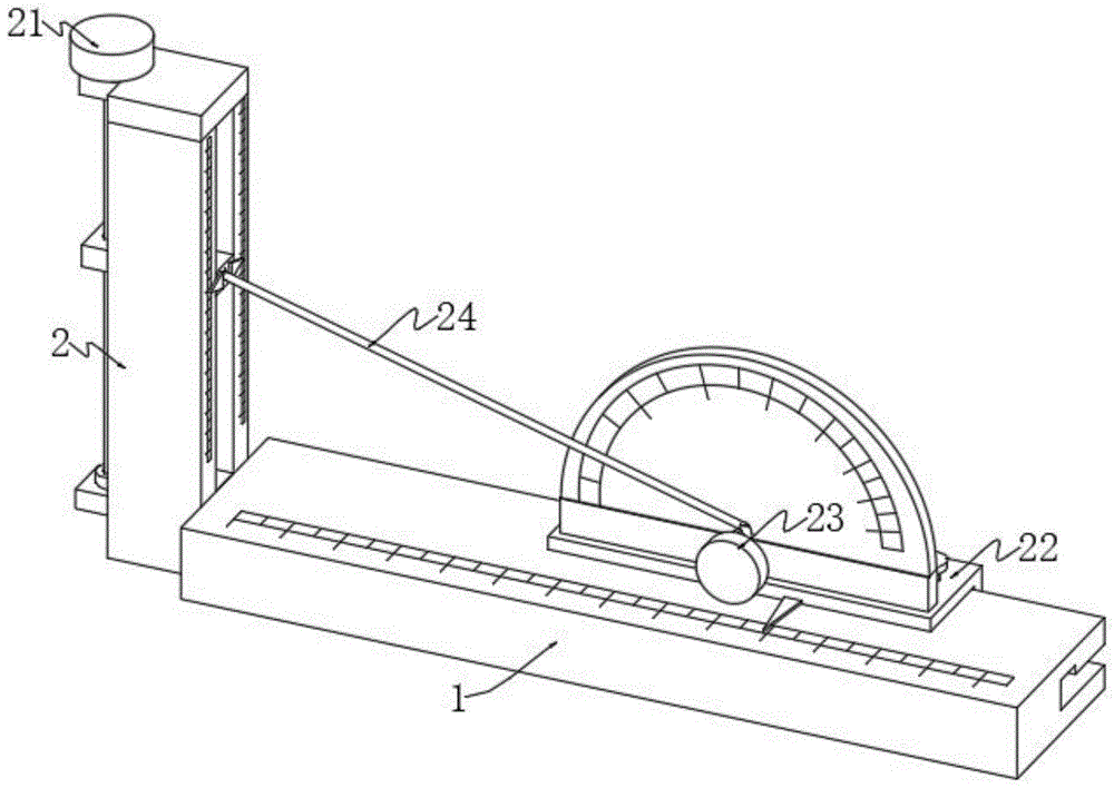
图1为本发明的整体结构示意图;Fig. 1 is the overall structure schematic diagram of the present invention;
图2为本发明中的剖视图;Fig. 2 is a sectional view among the present invention;
图3为本发明图2中A处的放大图;Fig. 3 is the enlarged view of place A in Fig. 2 of the present invention;
图4为本发明中矩形柱和底板的结构示意图;Fig. 4 is the structural representation of rectangular column and base plate among the present invention;
图5为本发明中联动杆和螺纹杆的结构示意图;Fig. 5 is the structural representation of linkage rod and threaded rod among the present invention;
图6为本发明中U型卡板和量角器的结构示意图;Fig. 6 is the structural representation of U-shaped pallet and protractor among the present invention;
图7为本发明中限位插条和U型卡板的结构示意图;Fig. 7 is a structural schematic diagram of a limit insert and a U-shaped clamping plate in the present invention;
图8为本发明中旋转轴和滚轮的结构示意图;Fig. 8 is a structural schematic diagram of a rotating shaft and a roller in the present invention;
图中:In the picture:
1、底板;2、测量机构;1. Bottom plate; 2. Measuring mechanism;
21、升降组件;211、矩形柱;212、上衔接块;213、下衔接块;214、第一轴承;215、螺纹杆;216、旋钮盘;217、联动杆;218、第一螺纹孔;219、左滑槽;2110、内置块;2111、右滑块;2112、贴合滑槽;2113、右滑槽;2114、上盖;21. Lifting assembly; 211. Rectangular column; 212. Upper connecting block; 213. Lower connecting block; 214. First bearing; 215. Threaded rod; 216. Knob plate; 217. Linkage rod; 218. First threaded hole; 219, left chute; 2110, built-in block; 2111, right slider; 2112, fitting chute; 2113, right chute; 2114, upper cover;
22、平移组件;221、U型卡板;222、方形插槽;223、限位插条;224、第二螺纹孔;225、螺纹旋钮;226、限位插槽;22. Translating component; 221. U-shaped card board; 222. Square slot; 223. Limit insert; 224. Second threaded hole; 225. Threaded knob; 226. Limit slot;
23、绕线组件;231、圆形杆;232、旋转轴;233、连接板;234、量角器;235、第二轴承;236、拉绳;237、贯通孔;238、L型槽;239、重力块;2310、滚轮;23, winding assembly; 231, round rod; 232, rotating shaft; 233, connecting plate; 234, protractor; 235, second bearing; 236, pull rope; 237, through hole; 238, L-shaped groove; 239, Gravity block; 2310, roller;
24、测量组件;241、第一指针;242、第二指针;243、第一刻度线;244、第二刻度线。24. Measuring component; 241, first pointer; 242, second pointer; 243, first scale line; 244, second scale line.
具体实施方式Detailed ways
下面将结合本发明实施例中的附图,对本发明实施例中的技术方案进行清楚、完整地描述,显然,所描述的实施例仅仅是本发明一部分实施例,而不是全部的实施例。基于本发明中的实施例,本领域普通技术人员在没有做出创造性劳动前提下所获得的所有其他实施例,都属于本发明保护的范围。The following will clearly and completely describe the technical solutions in the embodiments of the present invention with reference to the accompanying drawings in the embodiments of the present invention. Obviously, the described embodiments are only some, not all, embodiments of the present invention. Based on the embodiments of the present invention, all other embodiments obtained by persons of ordinary skill in the art without making creative efforts belong to the protection scope of the present invention.
如图1至图8所示;As shown in Figure 1 to Figure 8;
一种数学模型建模装置,包括底板1,还包括设置在底板1表面上的测量机构2;A mathematical model building device, including a base plate 1, and also includes a
测量机构2包括升降组件21、平移组件22、绕线组件23和测量组件24,升降组件21设置在底板1的左侧,平移组件22设置在底板1的表面,绕线组件23设置在平移组件22的表面,测量组件24设置在绕线组件23的表面。The
在一个可选的实施例中,升降组件21包括矩形柱211、上衔接块212、下衔接块213、第一轴承214、螺纹杆215和联动杆217,矩形柱211固定连接在底板1的左表面,联动杆217滑动连接在矩形柱211远离底板1一面开设的左滑槽219内,螺纹杆215螺接在联动杆217表面开设的第一螺纹孔218内,上衔接块212套接在螺纹杆215的表面,并与矩形柱211固定连接,下衔接块213固定连接在矩形柱211靠近上衔接块212的一面,第一轴承214固定连接在下衔接块213的上表面,且螺纹杆215的一端插设在第一轴承214的内壁面,并通过第一轴承214与下衔接块213转动连接。In an optional embodiment, the lifting
在一个可选的实施例中,升降组件21还包括内置块2110和右滑块2111,矩形柱211的右表面开设有右滑槽2113,且右滑块2111滑动连接在右滑槽2113的内壁面,矩形柱211的上表面开设有与左滑槽219和右滑槽2113相连通的贴合滑槽2112,且内置块2110滑动连接在贴合滑槽2112的内壁面,联动杆217和右滑块2111分别与内置块2110固定连接。In an optional embodiment, the lifting
在一个可选的实施例中,升降组件21还包括旋钮盘216和上盖2114,旋钮盘216固定连接在螺纹杆215远离下衔接块213的一端,上盖2114通过螺栓固定连接在矩形柱211的上表面。In an optional embodiment, the lifting
在一个可选的实施例中,平移组件22包括U型卡板221和限位插条223,底板1的后表面开设有方形插槽222,且U型卡板221滑动连接在方形插槽222的内壁面,方形插槽222的内壁面开设有限位插槽226,且限位插条223插设在限位插槽226的内壁面,限位插条223与U型卡板221固定连接,U型卡板221呈U型结构。In an optional embodiment, the translation assembly 22 includes a
在一个可选的实施例中,平移组件22还包括螺纹旋钮225,U型卡板221的上表面开设有第二螺纹孔224,且螺纹旋钮225螺接在第二螺纹孔224的内壁面,螺纹旋钮225的一端与底板1的表面相贴合。In an optional embodiment, the translation assembly 22 further includes a threaded
在一个可选的实施例中,绕线组件23包括圆形杆231、旋转轴232、连接板233、量角器234、第二轴承235、拉绳236、重力块239和滚轮2310,连接板233固定连接在U型卡板221的上表面,量角器234固定连接在连接板233的上表面,第二轴承235固定安装在连接板233的前表面,旋转轴232固定连接在第二轴承235的内壁面,且旋转轴232通过第二轴承235与连接板233转动连接,滚轮2310固定连接在旋转轴232远离连接板233的一端,且滚轮2310与底板1的表面相贴合,重力块239滑动连接在贴合滑槽2112的内壁面,并位于内置块2110的下方,拉绳236缠绕固定在旋转轴232的表面,圆形杆231固定连接在量角器234的表面,且拉绳236与圆形杆231的表面相贴合。In an optional embodiment, the winding assembly 23 includes a
在一个可选的实施例中,内置块2110靠近右滑块2111的一面开设有L型槽238,L型槽238呈直角状,右滑块2111的表面开设有贯通孔237,且拉绳236贯穿贯通孔237和L型槽238的内部,并与重力块239固定连接。In an optional embodiment, an L-shaped
在一个可选的实施例中,测量组件24包括第一指针241,矩形柱211靠近底板1的一面镶嵌有第一刻度线243,右滑块2111远离内置块2110的一面对称固定连接有第一指针241,第一刻度线243的零刻度线和量角器234的零刻度线在同一水平面。In an optional embodiment, the measurement assembly 24 includes a
在一个可选的实施例中,测量组件24还包括第二指针242,第二指针242固定连接在U型卡板221的前表面,且第二指针242与底板1的上表面相贴合,底板1的上表面靠近第二指针242的下方位置处镶嵌有第二刻度线244。In an optional embodiment, the measurement assembly 24 further includes a
本实施方案中:当该装置在使用时,如图1,拉绳236、底板1和矩形柱211所构成的图形为三角形,由于第一刻度线243的零刻度线和量角器234的零刻度线在同一水平面,故第一指针241所指向第一刻度线243上对应的刻度值为三角形竖直边的长度,底板1上表面镶嵌的第二刻度线244零刻度线处到矩形柱211之间的距离和第二指针242距离量角器234中线的水平距离相同,即第二指针242指在第二刻度线244上对应的刻度值为三角形水平边的长度,当需要对三角形竖直边的长度进行调整时,旋转旋钮盘216,旋钮盘216的转动带动螺纹杆215转动,螺纹杆215的转动在螺纹的作用下带动联动杆217在左滑槽219的内壁面滑动,联动杆217在移动的过程中带动内置块2110在贴合滑槽2112的内壁面滑动,内置块2110的移动带动右滑块2111在右滑槽2113的内壁面滑动,右滑块2111的移动带动第一指针241移动,直至第一指针241指在第一刻度线243上对应的刻度值上,内置块2110在贴合滑槽2112的内壁面滑动的过程中,在重力块239重力的作用下可使拉绳236在贯通孔237在L型槽238的内部滑动,从而使拉绳236始终处于绷紧状态,内置块2110的高度变化,从而使拉绳236的倾斜角度随之变化,通过观察拉绳236倾斜时压在量角器234表面对应的刻度值,即为该直角三角形底面的角度,且该三角形另外一个角的角度值为90减去该角度值,当需要改变该三角形另一边的长度时,旋转螺纹旋钮225,在第二螺纹孔224的作用下可使螺纹旋钮225向着远离底板1的方向移动,在螺纹旋钮225移动至适宜位置后,可推动U型卡板221在方形插槽222的内壁面滑动,U型卡板221在移动的过程中带动量角器234、连接板233和第二指针242同步移动,当U型卡板221向左移动时,连接板233的移动带动滚轮2310在底板1的表面滚动,滚轮2310的滚动带动旋转轴232转动,从而使拉绳236缠绕在旋转轴232的表面,当U型卡板221向右移动时,滚轮2310在底板1的表面滚动,滚轮2310的转动带动旋转轴232转动,从而使缠绕在旋转轴232表面的拉绳236松开,当U型卡板221移动至适宜位置后,旋转螺纹旋钮225在第二螺纹孔224的作用下可使螺纹旋钮225的一端抵住底板1的表面,从而对调整后U型卡板221的位置进行固定,有利于在改变三角形边长时减少重力块239在贴合滑槽2112内部的移动范围,从而增加三角形边长长度的调整范围,有利于方便观察直角三角形边长在变化时三角形角度的变化情况,避免数学教师通过量角器反复测量三角形的角度操作较为不便的现象发生。In this embodiment: when the device is in use, as shown in Figure 1, the figure formed by the
需要说明的是:该装置在使用时,如图1,拉绳236、底板1和矩形柱211所构成的图形为三角形,由于第一刻度线243的零刻度线和量角器234的零刻度线在同一水平面,故第一指针241所指向第一刻度线243上对应的刻度值为三角形竖直边的长度,底板1上表面镶嵌的第二刻度线244零刻度线处到矩形柱211之间的距离和第二指针242距离量角器234中线的水平距离相同,即第二指针242指在第二刻度线244上对应的刻度值为三角形水平边的长度。It should be noted that: when the device is in use, as shown in Figure 1, the figure formed by the
需要说明的是:圆形杆231位于量角器234的中心点上,以便于保证该三角形角度的准确性,圆形杆231压在量角器234上对应的刻度值,即为三角形的角度值。It should be noted that: the
需要说明的是:U型卡板221在方形插槽222的内壁面滑动的过程中,带动限位插条223在限位插槽226的内壁面滑动,从而对U型卡板221的位置进行限制,避免U型卡板221从方形插槽222的内部滑出的现象发生。It should be noted that: during the sliding process of the
需要说明的是:量角器234为测量角度的尺子,日常生活中较为常见,本发明中的量角器234具有一定的厚度,从而能固定在连接板233上。It should be noted that the
最后应说明的是:以上所述仅为本发明的优选实施例而已,并不用于限制本发明,尽管参照前述实施例对本发明进行了详细的说明,对于本领域的技术人员来说,其依然可以对前述各实施例所记载的技术方案进行修改,或者对其中部分技术特征进行等同替换。凡在本发明的精神和原则之内,所作的任何修改、等同替换、改进等,均应包含在本发明的保护范围之内。Finally, it should be noted that: the above is only a preferred embodiment of the present invention, and is not intended to limit the present invention. Although the present invention has been described in detail with reference to the foregoing embodiments, for those skilled in the art, it still The technical solutions recorded in the foregoing embodiments may be modified, or some technical features thereof may be equivalently replaced. Any modifications, equivalent replacements, improvements, etc. made within the spirit and principles of the present invention shall be included within the protection scope of the present invention.
Claims (10)
Priority Applications (1)
| Application Number | Priority Date | Filing Date | Title |
|---|---|---|---|
| CN202211037427.XA CN115376390A (en) | 2022-08-26 | 2022-08-26 | A mathematical model modeling device |
Applications Claiming Priority (1)
| Application Number | Priority Date | Filing Date | Title |
|---|---|---|---|
| CN202211037427.XA CN115376390A (en) | 2022-08-26 | 2022-08-26 | A mathematical model modeling device |
Publications (1)
| Publication Number | Publication Date |
|---|---|
| CN115376390A true CN115376390A (en) | 2022-11-22 |
Family
ID=84068749
Family Applications (1)
| Application Number | Title | Priority Date | Filing Date |
|---|---|---|---|
| CN202211037427.XA Withdrawn CN115376390A (en) | 2022-08-26 | 2022-08-26 | A mathematical model modeling device |
Country Status (1)
| Country | Link |
|---|---|
| CN (1) | CN115376390A (en) |
Cited By (1)
| Publication number | Priority date | Publication date | Assignee | Title |
|---|---|---|---|---|
| CN117329946A (en) * | 2023-11-28 | 2024-01-02 | 中建八局第一建设有限公司 | A panel size measuring device suitable for housing construction projects |
-
2022
- 2022-08-26 CN CN202211037427.XA patent/CN115376390A/en not_active Withdrawn
Cited By (2)
| Publication number | Priority date | Publication date | Assignee | Title |
|---|---|---|---|---|
| CN117329946A (en) * | 2023-11-28 | 2024-01-02 | 中建八局第一建设有限公司 | A panel size measuring device suitable for housing construction projects |
| CN117329946B (en) * | 2023-11-28 | 2024-02-09 | 中建八局第一建设有限公司 | A panel size measuring device suitable for housing construction projects |
Similar Documents
| Publication | Publication Date | Title |
|---|---|---|
| CN209745217U (en) | Measuring scale for detecting surface flatness of concrete member | |
| CN111964556A (en) | Measuring tool for horizontal metal tank and using method | |
| CN218765131U (en) | Automatic calibration measuring device for bearing inner diameter | |
| CN210930214U (en) | An adjustable drawing tablet for outdoor learning | |
| CN211291372U (en) | A New Vertical Flatness Measuring Tool | |
| CN216443370U (en) | an electronic compass | |
| CN217585807U (en) | Measuring device with comparison mark structure for building construction | |
| CN211969010U (en) | A multifunctional drawing ruler for mathematics teaching | |
| CN216562121U (en) | Teacher's teaching ability detection device | |
| CN216770450U (en) | Engineering quality supervise is with straightness detection device that hangs down | |
| CN211054802U (en) | Marketing teaching is with system drawing device | |
| CN206394333U (en) | A kind of Calculus Teaching assistant teaching aid | |
| CN218311024U (en) | Positioning device for punching in mold production | |
| CN207867774U (en) | A kind of angle of friction MEASUREMENT TEACHING tool | |
| CN219405960U (en) | Combined drawing rule for teaching | |
| CN224246904U (en) | Angle square calibrating device | |
| CN210070770U (en) | A measuring instrument for mathematics teaching | |
| CN208902214U (en) | A handheld water depth measurement device | |
| CN210149020U (en) | Measuring tool for mathematical education | |
| CN223412636U (en) | A portable mechanical measuring instrument | |
| CN211195605U (en) | Blackboard for teaching chinese language and literature | |
| CN219695907U (en) | An easily adjustable teaching tool rack | |
| CN219895008U (en) | Drawing board with stop mechanism | |
| CN220163533U (en) | Foldable ruler | |
| CN209541680U (en) | The portable plotting board in amount room suitable for indoor design |
Legal Events
| Date | Code | Title | Description |
|---|---|---|---|
| PB01 | Publication | ||
| PB01 | Publication | ||
| SE01 | Entry into force of request for substantive examination | ||
| SE01 | Entry into force of request for substantive examination | ||
| WW01 | Invention patent application withdrawn after publication | ||
| WW01 | Invention patent application withdrawn after publication |
Application publication date: 20221122 |