CN115370269A - Vertical sliding window - Google Patents
Vertical sliding window Download PDFInfo
- Publication number
- CN115370269A CN115370269A CN202210905979.1A CN202210905979A CN115370269A CN 115370269 A CN115370269 A CN 115370269A CN 202210905979 A CN202210905979 A CN 202210905979A CN 115370269 A CN115370269 A CN 115370269A
- Authority
- CN
- China
- Prior art keywords
- window
- frame
- sash
- glass
- groove
- Prior art date
- Legal status (The legal status is an assumption and is not a legal conclusion. Google has not performed a legal analysis and makes no representation as to the accuracy of the status listed.)
- Pending
Links
Images


Classifications
-
- E—FIXED CONSTRUCTIONS
- E06—DOORS, WINDOWS, SHUTTERS, OR ROLLER BLINDS IN GENERAL; LADDERS
- E06B—FIXED OR MOVABLE CLOSURES FOR OPENINGS IN BUILDINGS, VEHICLES, FENCES OR LIKE ENCLOSURES IN GENERAL, e.g. DOORS, WINDOWS, BLINDS, GATES
- E06B3/00—Window sashes, door leaves, or like elements for closing wall or like openings; Layout of fixed or moving closures, e.g. windows in wall or like openings; Features of rigidly-mounted outer frames relating to the mounting of wing frames
- E06B3/32—Arrangements of wings characterised by the manner of movement; Arrangements of movable wings in openings; Features of wings or frames relating solely to the manner of movement of the wing
- E06B3/34—Arrangements of wings characterised by the manner of movement; Arrangements of movable wings in openings; Features of wings or frames relating solely to the manner of movement of the wing with only one kind of movement
- E06B3/42—Sliding wings; Details of frames with respect to guiding
- E06B3/44—Vertically-sliding wings
-
- E—FIXED CONSTRUCTIONS
- E06—DOORS, WINDOWS, SHUTTERS, OR ROLLER BLINDS IN GENERAL; LADDERS
- E06B—FIXED OR MOVABLE CLOSURES FOR OPENINGS IN BUILDINGS, VEHICLES, FENCES OR LIKE ENCLOSURES IN GENERAL, e.g. DOORS, WINDOWS, BLINDS, GATES
- E06B3/00—Window sashes, door leaves, or like elements for closing wall or like openings; Layout of fixed or moving closures, e.g. windows in wall or like openings; Features of rigidly-mounted outer frames relating to the mounting of wing frames
- E06B3/54—Fixing of glass panes or like plates
- E06B3/58—Fixing of glass panes or like plates by means of borders, cleats, or the like
- E06B3/60—Fixing of glass panes or like plates by means of borders, cleats, or the like of clamping cleats of metal
Landscapes
- Engineering & Computer Science (AREA)
- Civil Engineering (AREA)
- Structural Engineering (AREA)
- Specific Sealing Or Ventilating Devices For Doors And Windows (AREA)
Abstract
本发明公开了一种提拉窗,包括:窗框;窗扇,其位于所述窗框内,所述窗扇内具有窗口,所述窗扇正对所述窗口的一侧由室内至室外的方向依次设置有压紧件与外挡板,所述外挡板环绕所述窗口延伸,所述压紧件环绕所述窗口设置有多个;玻璃,其位于所述窗口内,所述玻璃的室外侧相抵于所述外挡板,多个所述压紧件相抵于所述玻璃的室内侧,本发明使得玻璃安装更加方便,并且以压紧件与外挡板直接对玻璃夹紧固定,可减少玻璃两侧可活动的空隙,有利于减少玻璃的晃动,提高对玻璃安装的稳定性。
The invention discloses a sliding window, comprising: a window frame; a window sash, which is located in the window frame, a window is provided in the window sash, and the side of the window sash facing the window is sequentially from the indoor to the outdoor direction. A pressing member and an outer baffle are provided, and the outer baffle extends around the window, and a plurality of pressing members are arranged around the window; glass is located in the window, and the outer side of the glass is Against the outer baffle, a plurality of the pressing parts are against the indoor side of the glass. The invention makes the glass installation more convenient, and the pressing parts and the outer baffle are directly clamped and fixed to the glass, which can reduce the The movable gap on both sides of the glass is beneficial to reduce the shaking of the glass and improve the stability of the glass installation.
Description
技术领域technical field
本发明涉及一种门窗,尤其涉及一种提拉窗。The invention relates to a door and window, in particular to a sliding window.
背景技术Background technique
区别于传统的推拉或平开式的窗扇,在提拉窗中,窗扇可在窗框内上下活动,现有的提拉窗窗扇面积一般较小,只应用于普通的门窗洞口,随着人们需求的日益提高,市面上出现了一些窗扇面积较大的提拉窗,其可应用于大型门窗洞口,甚至用作于阳台外围,而窗扇面积增大的情况下,其玻璃面积亦会对应增大,现有的窗扇中一般将玻璃的侧边插入至两个固定的板体之间进行限位,难以对面积较大的玻璃进行稳固地定位,容易出现玻璃晃动、甚至掉落的现象。Different from the traditional push-pull or casement sash, in the pull-up window, the sash can move up and down in the window frame. The area of the existing pull-up window sash is generally small, and it is only used in ordinary door and window openings. As people With the increasing demand, some sliding windows with larger sash areas appear on the market, which can be applied to large door and window openings, and even used on the periphery of balconies. When the sash area increases, the glass area will also increase accordingly. Large, in the existing window sashes, the side of the glass is generally inserted between two fixed panels for positioning, it is difficult to stably position the glass with a large area, and the glass is prone to shaking or even falling.
发明内容Contents of the invention
本发明目的在于提供一种提拉窗,以解决现有技术中所存在的一个或多个技术问题,至少提供一种有益的选择或创造条件。The purpose of the present invention is to provide a sliding window to solve one or more technical problems in the prior art, and at least provide a beneficial option or create conditions.
本发明解决其技术问题的解决方案是:The solution that the present invention solves its technical problem is:
一种提拉窗,包括:窗框;窗扇,其位于所述窗框内,所述窗扇内具有窗口,所述窗扇正对所述窗口的一侧由室内至室外的方向依次设置有压紧件与外挡板,所述外挡板环绕所述窗口延伸,所述压紧件环绕所述窗口设置有多个;玻璃,其位于所述窗口内,所述玻璃的室外侧相抵于所述外挡板,多个所述压紧件相抵于所述玻璃的室内侧。A sliding window, comprising: a window frame; a window sash, which is located in the window frame, and has a window in the window sash, and the side of the window sash facing the window is sequentially provided with pressing part and an outer baffle, the outer baffle extends around the window, and a plurality of pressing parts are arranged around the window; glass, which is located in the window, and the outer side of the glass abuts against the For the outer baffle, the plurality of pressing parts are against the interior side of the glass.
该技术方案至少具有如下的有益效果:窗扇位于窗框内,在使用时,以窗框、窗扇与玻璃等结构件中正对于室内的一侧为室内侧,而另一侧则为室外侧,当需要将玻璃装入窗口时,将玻璃的室外侧相抵于外挡板,外挡板可限制玻璃向室外一侧掉落,然后将多个压紧件装入至窗扇上,利用压紧件相抵于玻璃的室内侧,将玻璃直接压紧于外挡板上,如此使得玻璃安装更加方便,并且以压紧件与外挡板直接对玻璃夹紧固定,可减少玻璃两侧可活动的空隙,有利于减少玻璃的晃动,提高对玻璃安装的稳定性。The technical solution has at least the following beneficial effects: the window sash is located in the window frame. When in use, the side of the structural members such as the window frame, window sash and glass facing the room is the indoor side, while the other side is the outdoor side. When it is necessary to install the glass into the window, put the outdoor side of the glass against the outer baffle, the outer baffle can limit the glass from falling to the outdoor side, then install multiple pressing parts on the window sash, and use the pressing parts to offset On the indoor side of the glass, the glass is directly pressed against the outer baffle, which makes the installation of the glass more convenient, and the glass is directly clamped and fixed by the pressing piece and the outer baffle, which can reduce the movable gap on both sides of the glass. It is beneficial to reduce the shaking of the glass and improve the stability of the glass installation.
作为上述技术方案的进一步改进,所述窗扇正对所述窗口的一侧设置有连接槽,所述连接槽环绕所述窗口设置,所述连接槽沿远离室内方向倾斜延伸,所述压紧件包括相互连接的压紧部与连接部,所述连接部上设置有通孔,所述压紧部沿靠近所述窗口中心的方向延伸,所述压紧部相抵于所述玻璃的室内侧,所述通孔内穿插有连接件,所述连接件配合连接于所述连接槽内。在打入压紧件时,连接件穿过连接部上的通孔再配合连接至通孔内,由于连接槽倾斜延伸,连接件将连接部压紧至窗扇时,可产生远离窗口方向的分力以及向外挡板方向的分力,如此可对玻璃形成压紧至窗扇上的压力以及压紧于外挡板上的压力,使得玻璃安装定位更加稳固。As a further improvement of the above technical solution, the side of the sash facing the window is provided with a connection groove, the connection groove is arranged around the window, the connection groove extends obliquely away from the indoor direction, and the pressing member It includes a pressing part and a connecting part connected to each other, the connecting part is provided with a through hole, the pressing part extends in a direction close to the center of the window, the pressing part abuts against the interior side of the glass, A connecting piece is inserted into the through hole, and the connecting piece is mated and connected in the connecting groove. When the pressing piece is driven in, the connecting piece passes through the through hole on the connecting part and then fits into the through hole. Since the connecting groove extends obliquely, when the connecting piece presses the connecting part to the window sash, it can produce a separation away from the direction of the window. In this way, the glass can be pressed against the window sash and pressed against the outer baffle, making the glass installation and positioning more stable.
作为上述技术方案的进一步改进,所述窗扇正对所述窗口的一侧可拆卸地连接有装饰板,所述装饰板的室外侧设置有收纳槽,所述压紧部位于所述收纳槽内。装饰板可对压紧件进行遮挡保护,并且在装入至窗扇时,压紧部可收入至收纳槽内,以减少装饰板占用的厚度,当需要拆装压紧件时,将装饰板拆出,即可使得压紧件外露。As a further improvement of the above technical solution, the side of the window sash facing the window is detachably connected with a decorative plate, the outdoor side of the decorative plate is provided with a storage groove, and the pressing part is located in the storage groove . The decorative board can shield and protect the pressing part, and when it is installed in the window sash, the pressing part can be stored in the storage groove to reduce the thickness occupied by the decorative board. When it is necessary to disassemble the pressing part, remove the decorative board out, the pressing part can be exposed.
作为上述技术方案的进一步改进,所述装饰板与所述玻璃之间填充有密封胶层。密封胶层可填补装饰板靠近窗口的位置与玻璃之间的空隙,有利于提高整体的气密性与防水性。As a further improvement of the above technical solution, a sealant layer is filled between the decorative plate and the glass. The sealant layer can fill the gap between the position of the decorative panel near the window and the glass, which is beneficial to improve the overall airtightness and waterproofness.
作为上述技术方案的进一步改进,所述压紧部与所述玻璃之间设置有垫块。压紧部通过垫块压紧于玻璃上,可提高对玻璃的保护,避免压紧件直接按压作用于玻璃上而对玻璃造成损坏。As a further improvement of the above technical solution, a spacer is provided between the pressing part and the glass. The pressing part is pressed against the glass by the spacer, which can improve the protection of the glass and prevent the glass from being damaged by the pressing part directly pressing on the glass.
作为上述技术方案的进一步改进,所述窗框的顶部包括沿水平方向延伸的上顶框、可拆卸地连接于所述上顶框底侧的转换框与扣盖,所述扣盖位于所述转换框的室内侧,所述转换框的底侧设置有上扇槽,所述窗扇的顶侧可进出于所述上扇槽,所述上顶框内部设置有容纳腔,所述扣盖与所述转换框的室外侧之间围设形成收纳腔,所述扣盖的底侧与所述转换框的底侧之间具有与所述收纳腔相互连通的间隙。上顶框的容纳腔内可装入外设的用于对窗扇提拉活动的电机驱动结构,当窗扇向上活动到位时,窗扇的顶侧可进入上扇槽内,而转换框与扣盖之间则围设形成用于对纱网进行收纳遮挡的收纳腔,纱网可从间隙拉出收纳腔,纱网主要连接至外设窗框的两侧受力,使用时,转换框位于室外侧,扣盖位于室内侧,当需要对纱网进行维护时,直接将扣盖从上顶框上拆出即可打开收纳腔,如需要进一步维护容纳腔内的电机驱动结构时,亦可将转换框与扣盖拆出上顶框,如此提高了对装入至上顶框内的结构件进行拆装维护的便捷性,并形成了不同的腔体对结构件进行规整,使得腔体内的结构不容易相互干涉、缠绕,提高整体使用体验。As a further improvement of the above technical solution, the top of the window frame includes an upper top frame extending in the horizontal direction, a conversion frame and a buckle cover detachably connected to the bottom side of the upper top frame, and the buckle cover is located on the On the indoor side of the conversion frame, the bottom side of the conversion frame is provided with an upper fan groove, the top side of the window sash can enter and exit the upper fan groove, and the inside of the upper top frame is provided with an accommodation chamber, and the buckle cover and A storage cavity is formed between the outdoor sides of the conversion frame, and there is a gap communicating with the storage cavity between the bottom side of the buckle cover and the bottom side of the conversion frame. The accommodating cavity of the upper top frame can be installed with the motor drive structure of the peripheral equipment for lifting and pulling the window sash. When the window sash moves upwards to the right position, the top side of the window sash can enter the upper sash groove, and the transition frame and the buckle cover The room is surrounded by a storage cavity for storing and covering the gauze. The gauze can be pulled out of the storage cavity from the gap. The gauze is mainly connected to the external window frame for stress on both sides. When in use, the conversion frame is located outside the outdoor , the buckle cover is located on the inner side of the room. When it is necessary to maintain the gauze, directly remove the buckle cover from the top frame to open the storage chamber. If further maintenance is required for the motor drive structure in the storage chamber, the switch The frame and buckle cover are removed from the top frame, which improves the convenience of disassembly and maintenance of the structural parts installed in the top frame, and forms different cavities to regularize the structural parts, so that the structure in the cavity is not It is easy to interfere with each other and get entangled, which improves the overall user experience.
作为上述技术方案的进一步改进,所述窗扇的数量有两个,一个所述窗扇为固定扇,一个所述窗扇为活动扇,所述固定扇的顶部室外侧连接有上勾板,所述上勾板与所述固定扇之间形成槽口向下的上勾槽,所述上勾槽内设置有第一胶条,所述固定扇的顶部室外侧设置有第二胶条,所述第二胶条位于所述上勾板的上方,所述活动扇的底部室内侧连接有下勾板,所述下勾板与所述活动扇之间形成槽口向上的下勾槽,所述下勾槽内设置有第三胶条,所述活动扇的底部室内侧设置有第四胶条,所述第四胶条位于所述下勾板的下方,所述上勾板插入所述下勾槽内并与所述第三胶条相抵,所述下勾板插入所述上勾槽内并与所述第一胶条相抵,所述第二胶条相抵于所述固定扇,所述第四胶条相抵于所述活动扇。当固定扇与活动扇对窗框遮挡封闭时,上勾板与下勾板分别插入下勾槽与上勾槽内,使得两个窗扇相互勾紧,并且上勾板相抵于第三胶条、下勾板相抵于第一胶条,如此可进一步提高两个窗扇之间的连接稳定性,减少晃动,并增强密封性,形成了双重密封结构,另外,第二胶条相抵于固定扇,形成一重密封结构,第四胶条相抵于活动扇,形成另一重密封结构,如此通过多重密封结构,填补了两个窗扇之间的装配空位,极大地提高了两个窗扇连接位置的密封性,从而提高整窗使用时的气密性、保温性与防水性。As a further improvement of the above-mentioned technical solution, there are two windows, one of which is a fixed window and one of which is a movable window, and an upper hook plate is connected to the outside of the top of the fixed window. An upper hook groove with a downward notch is formed between the hook plate and the fixed fan. A first rubber strip is arranged in the upper hook groove, and a second rubber strip is arranged outside the top of the fixed fan. The two rubber strips are located above the upper hook plate, and the bottom indoor side of the movable fan is connected with a lower hook plate. A lower hook groove with an upward notch is formed between the lower hook plate and the movable fan. A third rubber strip is arranged in the hook groove, and a fourth rubber strip is arranged on the inner side of the bottom chamber of the movable fan. The fourth rubber strip is located below the lower hook plate, and the upper hook plate is inserted into the lower hook plate. slot and against the third rubber strip, the lower hook plate is inserted into the upper hook groove and against the first rubber strip, the second rubber strip is against the fixed fan, and the first The four rubber strips are against the movable fan. When the fixed sash and the movable sash are closed to the window frame, the upper hook plate and the lower hook plate are respectively inserted into the lower hook groove and the upper hook groove, so that the two sashes are hooked tightly to each other, and the upper hook plate is against the third rubber strip, The lower hook plate is against the first rubber strip, which can further improve the connection stability between the two sashes, reduce shaking, and enhance the sealing performance, forming a double sealing structure. In addition, the second rubber strip is against the fixed sash, forming One seal structure, the fourth rubber strip is against the movable sash to form another seal structure, so through the multiple seal structure, the assembly space between the two sashes is filled, and the sealing of the joint position of the two sashes is greatly improved, thus Improve the air tightness, thermal insulation and water resistance of the whole window when used.
作为上述技术方案的进一步改进,所述窗框的两侧均包括侧边框、中转框与内封盖,所述侧边框正对窗口的一侧由室外至室内的方向依次连接有外挡盖、所述中转框与所述内封盖,所述外挡盖与所述中转框之间围设形成槽口朝向窗口的侧扇槽,所述中转框的室内侧开设有洞口,所述内封盖可拆卸地连接于所述中转框的一侧并遮挡所述洞口,所述窗扇可在窗框内上下活动并伸入所述窗框两侧的侧扇槽内。在窗框的任意一侧中,中转框连接至侧边框上,与侧边框上的外挡盖围设形成侧扇槽,在实际应用中,可采用不同结构的中转框,与侧边框相互搭配形成侧扇槽,侧扇槽可对在窗框内上下活动的窗扇侧边进行限位,将中转框装入侧边框后,可通过洞口在中转框与侧边框之间打入外设的结构固定件,以将中转框与侧边框进一步固定连接,并且安装维护更加方便,提高整体结构稳定性,最后将外挡盖装入至侧边框上,从而对洞口进行遮挡。As a further improvement of the above technical solution, both sides of the window frame include a side frame, a transfer frame and an inner cover, and the side of the side frame facing the window is sequentially connected with an outer cover, The transfer frame and the inner cover, the outer cover and the transfer frame are surrounded by a side fan groove with a notch facing the window, the inner side of the transfer frame is provided with a hole, and the inner seal The cover is detachably connected to one side of the transfer frame and covers the opening, and the window sash can move up and down in the window frame and extend into the side sash grooves on both sides of the window frame. On either side of the window frame, the transfer frame is connected to the side frame, and forms a side fan groove with the outer cover on the side frame. In practical applications, transfer frames of different structures can be used to match with the side frame Form the side fan groove, which can limit the side of the window sash moving up and down in the window frame. After the transfer frame is installed in the side frame, the peripheral structure can be inserted between the transfer frame and the side frame through the hole The fixing parts are used to further fix the connection between the transfer frame and the side frame, and the installation and maintenance are more convenient, and the stability of the overall structure is improved. Finally, the outer cover is installed on the side frame to cover the opening.
作为上述技术方案的进一步改进,所述外挡盖与所述中转框之间还围设有滑腔,所述侧扇槽与所述滑腔之间设置有槽孔,所述窗扇的两侧均连接有限位板,所述限位板穿过所述槽孔并伸入所述滑腔内,所述限位板上设置有滚轮,所述滚轮的旋转轴线沿左右方向延伸。限位板穿过槽孔后,可通过槽孔对限位板从室内至室外的方向进行限位,并且可通过滚轮在相抵于滑腔的内壁进行滑动,使得窗扇运动更加平稳。As a further improvement of the above-mentioned technical solution, a sliding chamber is provided between the outer cover and the transfer frame, and a slot hole is provided between the side fan groove and the sliding chamber, and the two sides of the window sash Both are connected with a limit plate, and the limit plate passes through the slot hole and extends into the sliding cavity, and a roller is arranged on the limit plate, and the rotation axis of the roller extends along the left and right directions. After the limiting plate passes through the slot hole, the direction of the limiting plate from indoor to outdoor can be limited through the slot hole, and the roller can slide against the inner wall of the sliding chamber, so that the movement of the window sash is more stable.
作为上述技术方案的进一步改进,所述外挡盖的室内侧连接有第一挡板,所述中转框的室外侧连接有第二挡板,所述第一挡板与所述第二挡板分别位于所述滚轮的两个对角之外。第一挡板与第二挡片在滑腔内对滚轮的位置进行限定,从远离或靠近窗口中心的方向对窗扇的活动进行限位,可减少滚轮在使用过程中在滑腔上打滑或偏移,进一步提高窗扇使用时的稳定性。As a further improvement of the above technical solution, a first baffle is connected to the indoor side of the outer baffle, a second baffle is connected to the outdoor side of the transfer frame, and the first baffle and the second baffle are are respectively located outside the two opposite corners of the rollers. The first baffle and the second baffle limit the position of the rollers in the sliding chamber, and limit the movement of the sash from the direction away from or close to the center of the window, which can reduce the sliding or deviation of the rollers on the sliding chamber during use. Move to further improve the stability of the sash when in use.
附图说明Description of drawings
为了更清楚地说明本发明实施例中的技术方案,下面将对实施例描述中所需要使用的附图作简单说明。显然,所描述的附图只是本发明的一部分实施例,而不是全部实施例,本领域的技术人员在不付出创造性劳动的前提下,还可以根据这些附图获得其他设计方案和附图。In order to more clearly illustrate the technical solutions in the embodiments of the present invention, the following will briefly describe the drawings that need to be used in the description of the embodiments. Apparently, the described drawings are only some embodiments of the present invention, not all embodiments, and those skilled in the art can obtain other designs and drawings based on these drawings without creative work.
图1是本发明的整体示意图;Fig. 1 is the overall schematic diagram of the present invention;
图2是图1的A-A剖面结构示意图;Fig. 2 is a schematic diagram of the A-A sectional structure of Fig. 1;
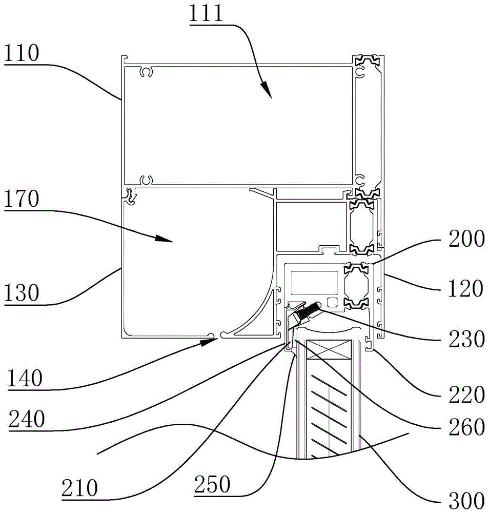
图3是图1的B-B剖面结构示意图;Fig. 3 is the B-B sectional structure schematic diagram of Fig. 1;
图4是图1的C-C剖面结构示意图。FIG. 4 is a schematic diagram of the C-C section structure in FIG. 1 .
附图中:100-窗框、110-上顶框、111-容纳腔、120-转换框、130-扣盖、140-间隙、150-限位板、160-滚轮、170-收纳腔、200-窗扇、210-压紧件、220-外挡板、230-连接件、240-装饰板、250-密封胶层、260-垫块、300-玻璃、410-固定扇、411-上勾板、412-第一胶条、413-第二胶条、420-活动扇、421-下勾板、422-第三胶条、423-第四胶条、510-侧边框、511-外挡盖、512-第一挡板、520-中转框、521-第二挡板、530-内封盖、541-滑腔、542-槽孔。In the attached drawings: 100-window frame, 110-top frame, 111-accommodating chamber, 120-converting frame, 130-button cover, 140-gap, 150-limiting plate, 160-roller, 170-accommodating chamber, 200 -window sashes, 210-pressing parts, 220-outer baffles, 230-connectors, 240-decorative panels, 250-sealant layer, 260-pads, 300-glass, 410-fixed fans, 411-upper hooks , 412-first rubber strip, 413-second rubber strip, 420-movable fan, 421-lower hook plate, 422-third rubber strip, 423-fourth rubber strip, 510-side frame, 511-outer cover , 512-first baffle plate, 520-transfer frame, 521-second baffle plate, 530-inner cover, 541-sliding cavity, 542-slot hole.
具体实施方式Detailed ways
下面详细描述本发明的实施例,所述实施例的示例在附图中示出,其中自始至终相同或类似的标号表示相同或类似的元件或具有相同或类似功能的元件。下面通过参考附图描述的实施例是示例性的,仅用于解释本发明,而不能理解为对本发明的限制。Embodiments of the present invention are described in detail below, examples of which are shown in the drawings, wherein the same or similar reference numerals designate the same or similar elements or elements having the same or similar functions throughout. The embodiments described below by referring to the figures are exemplary only for explaining the present invention and should not be construed as limiting the present invention.
在本发明的描述中,需要理解的是,涉及到方位描述,例如上、下、前、后、左、右等指示的方位或位置关系为基于附图所示的方位或位置关系,仅是为了便于描述本发明和简化描述,而不是指示或暗示所指的装置或元件必须具有特定的方位、以特定的方位构造和操作,因此不能理解为对本发明的限制。In the description of the present invention, it should be understood that the orientation descriptions, such as up, down, front, back, left, right, etc. indicated orientations or positional relationships are based on the orientations or positional relationships shown in the drawings, and are only In order to facilitate the description of the present invention and simplify the description, it does not indicate or imply that the device or element referred to must have a specific orientation, be constructed and operated in a specific orientation, and thus should not be construed as limiting the present invention.
在本发明的描述中,若干的含义是一个或者多个,多个的含义是两个以上,大于、小于、超过等理解为不包括本数,以上、以下、以内等理解为包括本数。如果有描述到第一、第二只是用于区分技术特征为目的,而不能理解为指示或暗示相对重要性或者隐含指明所指示的技术特征的数量或者隐含指明所指示的技术特征的先后关系。In the description of the present invention, several means one or more, and multiple means more than two. Greater than, less than, exceeding, etc. are understood as not including the original number, and above, below, within, etc. are understood as including the original number. If the description of the first and second is only for the purpose of distinguishing the technical features, it cannot be understood as indicating or implying the relative importance or implicitly indicating the number of the indicated technical features or implicitly indicating the order of the indicated technical features relation.
本发明的描述中,除非另有明确的限定,设置、安装、连接等词语应做广义理解,所属技术领域技术人员可以结合技术方案的具体内容合理确定上述词语在本发明中的具体含义。In the description of the present invention, unless otherwise clearly defined, words such as setting, installation, and connection should be understood in a broad sense, and those skilled in the art can reasonably determine the specific meanings of the above words in the present invention in combination with the specific content of the technical solution.
参照图1与图2,一种提拉窗,包括窗框100、窗扇200与玻璃300,在使用时,以窗框100、窗扇200与玻璃300等结构件中正对于室内的一侧为室内侧,而另一侧则为室外侧,其中,窗扇200位于所述窗框100内,一般窗扇200具有至少两个,一个为可上下活动的,而另一个为固定的,又可以是两个都为可上下活动的,所述窗扇200包括扇框,由扇框围设形成窗口,将玻璃300装设于窗口内用于遮挡窗口,所述窗扇200正对所述窗口的一侧由室内至室外的方向依次设置有压紧件210与外挡板220,所述外挡板220环绕所述窗口延伸,所述压紧件210环绕所述窗口设置有多个,所述玻璃300的室外侧相抵于所述外挡板220,多个所述压紧件210相抵于所述玻璃300的室内侧。Referring to Fig. 1 and Fig. 2, a sliding window includes a
由上述可知,窗扇200位于窗框100内,当需要将玻璃300装入窗口时,将玻璃300的室外侧相抵于外挡板220,外挡板220可限制玻璃300向室外一侧掉落,然后将多个压紧件210装入至窗扇200上,利用压紧件210相抵于玻璃300的室内侧,将玻璃300直接压紧于外挡板220上,如此使得玻璃300安装更加方便,并且以压紧件210与外挡板220直接对玻璃300夹紧固定,可减少玻璃300两侧可活动的空隙,有利于减少玻璃300的晃动,提高对玻璃300安装的稳定性。It can be seen from the above that the
压紧件210在窗扇200上可进行拆装,从而方便对玻璃300的拆装,为了实现将压紧件210连接至窗扇200上,在本实施例中,所述窗扇200正对所述窗口的一侧设置有连接槽,所述连接槽环绕所述窗口设置,所述连接槽沿远离室内方向倾斜延伸,所述压紧件210包括相互连接的压紧部与连接部,所述连接部上设置有通孔,所述压紧部沿靠近所述窗口中心的方向延伸,所述压紧部相抵于所述玻璃300的室内侧,所述通孔内穿插有连接件230,所述连接件230配合连接于所述连接槽内,在实际应用中,连接槽的内侧壁上设置有条形的凹槽,条形凹槽沿连接槽的深度方向设置有多个,如此形成可配合螺纹连接的螺纹槽,连接件230可为带有螺纹的结构件,通过与螺纹槽的逐渐配合,从而将连接部逐渐压紧于窗扇200上,例如,连接件230可选用螺丝、螺栓等连接结构。The pressing
在打入压紧件210时,连接件230穿过连接部上的通孔再配合连接至通孔内,由于连接槽倾斜延伸,连接件230将连接部压紧至窗扇200时,可产生远离窗口方向的分力以及向外挡板220方向的分力,如此可对玻璃300形成压紧至窗扇200上的压力以及压紧于外挡板220上的压力,使得玻璃300安装定位更加稳固。When the
为了提高整体外观,在本实施例中,所述窗扇200正对所述窗口的一侧可拆卸地连接有装饰板240,如装饰板240的底侧通过卡扣连接于窗扇200上,所述装饰板240的室外侧设置有收纳槽,所述压紧部位于所述收纳槽内。装饰板240可对压紧件210进行遮挡保护,并且在装入至窗扇200时,压紧部可收入至收纳槽内,以减少装饰板240占用的厚度,当需要拆装压紧件210时,将装饰板240拆出,即可使得压紧件210外露。In order to improve the overall appearance, in this embodiment, the side of the
装饰板240不仅可对压紧件210进行遮挡,以提高外观,还可对玻璃300进行保护,减少外物进入至玻璃300的底侧,为了提高整个窗扇200的密封性,在本实施例中,所述装饰板240与所述玻璃300之间填充有密封胶层250。密封胶层250可填补装饰板240靠近窗口的位置与玻璃300之间的空隙,有利于提高整体的气密性与防水性。The
随着连接件230与连接槽的逐渐配合,逐渐加大压紧部对玻璃300的压紧力,使得玻璃300安装更加稳固,在实际应用中,压紧件210通常为金属件,从而确保在压紧时具有足够的结构强度,而金属的压紧件210对玻璃300施力时容易对玻璃300造成损伤,在本实施例中,所述压紧部与所述玻璃300之间设置有垫块260。压紧部通过垫块260压紧于玻璃300上,可提高对玻璃300的保护,避免压紧件210直接按压作用于玻璃300上而对玻璃300造成损坏。As the connecting
对于窗框100,通常分为沿水平方向延伸的上边框与下边框、沿竖直方向延伸的侧边框510,侧边框510的数量有两条,上边框的两端分别连接至两个侧边框510的顶端,下边框的两端分别连接至两个侧边框510的底端,从而围设形成安装于门窗洞口的窗框100,而在实际使用时,对于提拉窗的使用功能分类,可分为手动提拉活动的提拉窗,亦可分为电动提拉活动的提拉窗,还可分为是否带有纱网的提拉窗,如提拉窗中需要实现电动提拉活动,并且带有纱网功能时,则需要对窗框100进行设计,以装入多种结构,在本实施例中,所述窗框100的顶部,亦即上边框包括沿水平方向延伸的上顶框110、可拆卸地连接于所述上顶框110底侧的转换框120与扣盖130,上边框的两端连接至两个侧边框510上,所述扣盖130位于所述转换框120的室内侧,所述转换框120的底侧设置有上扇槽,在窗框100内可上下活动的窗扇200,其顶侧可进出于所述上扇槽,所述上顶框110内部设置有容纳腔111,所述扣盖130与所述转换框120的室外侧之间围设形成收纳腔170,所述扣盖130的底侧与所述转换框120的底侧之间具有与所述收纳腔170相互连通的间隙140。The
在上述的窗框100顶部结构中,上顶框110的容纳腔111内可装入外设的用于对窗扇200提拉活动的电机驱动结构,当窗扇200向上活动到位时,窗扇200的顶侧可进入上扇槽内,而转换框120与扣盖130之间则围设形成用于对纱网进行收纳遮挡的收纳腔170,纱网可从间隙140拉出收纳腔170,纱网主要连接至外设窗框100的两侧受力,使用时,转换框120位于室外侧,扣盖130位于室内侧,当需要对纱网进行维护时,直接将扣盖130从上顶框110上拆出即可打开收纳腔170,如需要进一步维护容纳腔111内的电机驱动结构时,亦可将转换框120与扣盖130拆出上顶框110,如此提高了对装入至上顶框110内的结构件进行拆装维护的便捷性,并形成了不同的腔体对结构件进行规整,使得腔体内的结构不容易相互干涉、缠绕,提高整体使用体验。In the above-mentioned top structure of the
在上述实施例中,转换框120装入至上顶框110后,可采用上顶框110的左侧搭在转换框120左侧的设计,亦可直接将转换框120直接拼接至上顶框110的底侧,并使得转换框120的左侧与上顶框110的左侧相互齐平,而为了使得两者连接更加紧密,在本实施例中,所述转换框120的右侧设置有定位台阶,所述上顶框110的右侧设置有向下延伸的下延段,所述下延段伸入所述定位台阶内,所述转换框120的右侧面与所述上顶框110的右侧面相互齐平。在安装转换框120时,可将上顶框110的下延段伸入至定位台阶内定位,使得转换框120可更快速、稳固地装入至上顶框110的底侧,并且下延段配合连接至定位台阶处,可提高上顶框110与转换框120之间的连接紧密性,不容易从连接处向转换框120内部渗水。In the above-mentioned embodiment, after the
作为转换框120拆装连接至上顶框110底侧的具体实施例,所述上顶框110的底侧设置有向左弯折的上卡接勾,所述转换框120的顶侧设置有向右弯折的下卡接勾,所述上卡接勾与所述下卡接勾相互勾接。将下延段插入定位台阶内定位后,可再将上卡接勾插入下卡接勾与转换框120底侧形成的下卡接槽内、下卡接勾插入上卡接勾与上顶框110形成的上卡接槽内,实现上卡接勾与下卡接勾的相互勾接,使得转换框120稳定地连接至上顶框110上。As a specific embodiment in which the
转换框120通过相互勾接的结构连接至上顶框110后,为了进一步提高两者连接结构的稳定性,在本实施例中,所述转换框120的左侧连接有连接板,所述连接板向左上方延伸并相抵于所述上顶框110的底侧,所述连接板上穿设有螺丝,所述螺丝连接于所述上顶框110上。螺丝从连接板处连接至上顶框110上,由于连接板向左上方倾斜延伸,螺丝将连接板压紧在上顶框110上的压紧力朝向右上方,从而使得下延段与转换框120上的定位台阶配合更加紧密,转换框120可更稳固地连接至上顶框110的底侧。After the
所述窗扇200的数量有两个,一个所述窗扇200为固定扇410,一个所述窗扇200为活动扇420,如固定扇410位于窗框100的底部,而活动扇420则可在窗框100内上下活动,当活动扇420活动至窗框100顶部时,活动扇420与固定扇410共同关闭窗框100,而为了提高此时活动扇420与固定扇410的连接密封性,如图3所示,在本实施例中,所述固定扇410的顶部室外侧连接有上勾板411,所述上勾板411与所述固定扇410之间形成槽口向下的上勾槽,所述上勾槽内设置有第一胶条412,所述固定扇410的顶部室外侧设置有第二胶条413,所述第二胶条413位于所述上勾板411的上方,所述活动扇420的底部室内侧连接有下勾板421,所述下勾板421与所述活动扇420之间形成槽口向上的下勾槽,所述下勾槽内设置有第三胶条422,所述活动扇420的底部室内侧设置有第四胶条423,所述第四胶条423位于所述下勾板421的下方,所述上勾板411插入所述下勾槽内并与所述第三胶条422相抵,所述下勾板421插入所述上勾槽内并与所述第一胶条412相抵,所述第二胶条413相抵于所述固定扇410,所述第四胶条423相抵于所述活动扇420。There are two
当固定扇410与活动扇420对窗框100遮挡封闭时,上勾板411与下勾板421分别插入下勾槽与上勾槽内,使得两个窗扇200相互勾紧,并且上勾板411相抵于第三胶条422、下勾板421相抵于第一胶条412,如此可进一步提高两个窗扇200之间的连接稳定性,减少晃动,并增强密封性,形成了双重密封结构,另外,第二胶条413相抵于固定扇410,形成一重密封结构,第四胶条423相抵于活动扇420,形成另一重密封结构,如此通过多重密封结构,填补了两个窗扇200之间的装配空位,极大地提高了两个窗扇200连接位置的密封性,从而提高整窗使用时的气密性、保温性与防水性。When the fixed
如图4所示,所述窗框100的两侧均包括侧边框510、中转框520与内封盖530,上顶框110的端部连接至侧边框510的底端,而下边框的端部连接至侧边框510的底端,所述侧边框510正对窗口的一侧由室外至室内的方向依次连接有外挡盖511、所述中转框520与所述内封盖530,所述外挡盖511与所述中转框520之间围设形成槽口朝向窗口的侧扇槽,所述中转框520的室内侧开设有洞口,所述内封盖530可拆卸地连接于所述中转框520的一侧并遮挡所述洞口,所述窗扇200可在窗框100内上下活动并伸入所述窗框100两侧的侧扇槽内。As shown in Figure 4, both sides of the
在窗框100的任意一侧中,中转框520连接至侧边框510上,与侧边框510上的外挡盖511围设形成侧扇槽,在实际应用中,可采用不同结构的中转框520,与侧边框510相互搭配形成侧扇槽,侧扇槽可对在窗框100内上下活动的窗扇200侧边进行限位,将中转框520装入侧边框510后,可通过洞口在中转框520与侧边框510之间打入外设的结构固定件,以将中转框520与侧边框510进一步固定连接,并且安装维护更加方便,提高整体结构稳定性,最后将外挡盖511装入至侧边框510上,从而对洞口进行遮挡。另外,中转框520可作为固定扇410的侧边扇框,中转框520上同样具有连接槽、压紧件210等对玻璃300夹紧固定的结构。On either side of the
为了减少活动扇420在窗框100内上下活动时的晃动,在本实施例中,所述外挡盖511与所述中转框520之间还围设有滑腔541,所述侧扇槽与所述滑腔541之间设置有槽孔542,所述窗扇200的两侧均连接有限位板150,所述限位板150穿过所述槽孔542并伸入所述滑腔541内,所述限位板150上设置有滚轮160,所述滚轮160的旋转轴线沿左右方向延伸。限位板150穿过槽孔542后,可通过槽孔542对限位板150从室内至室外的方向进行限位,并且可通过滚轮160在相抵于滑腔541的内壁进行滑动,使得窗扇200运动更加平稳。In order to reduce the shaking when the
为了对滚轮160的位置进一步限位,在本实施例中,所述外挡盖511的室内侧连接有第一挡板512,所述中转框520的室外侧连接有第二挡板521,所述第一挡板512与所述第二挡板521分别位于所述滚轮160的两个对角之外,亦即第一挡板512与第二挡板521对滚轮160的左右两侧限位,在实际应用中,第一挡板512与第二挡板521均为贴合滚轮160边角形状的弧形设计,与滚轮160的两个对角相抵。第一挡板512与第二挡片在滑腔541内对滚轮160的位置进行限定,从远离或靠近窗口中心的方向对窗扇200的活动进行限位,可减少滚轮160在使用过程中在滑腔541上打滑或偏移,进一步提高窗扇200使用时的稳定性。In order to further limit the position of the
以上对本发明的较佳实施方式进行了具体说明,但本发明创造并不限于所述实施例,熟悉本领域的技术人员在不违背本发明精神的前提下还可作出种种的等同变型或替换,这些等同的变型或替换均包含在本申请权利要求所限定的范围内。The preferred embodiments of the present invention have been described in detail above, but the invention is not limited to the described embodiments, and those skilled in the art can also make various equivalent modifications or replacements without violating the spirit of the present invention. These equivalent modifications or replacements are all within the scope defined by the claims of the present application.
Claims (10)
Priority Applications (1)
| Application Number | Priority Date | Filing Date | Title |
|---|---|---|---|
| CN202210905979.1A CN115370269A (en) | 2022-07-29 | 2022-07-29 | Vertical sliding window |
Applications Claiming Priority (1)
| Application Number | Priority Date | Filing Date | Title |
|---|---|---|---|
| CN202210905979.1A CN115370269A (en) | 2022-07-29 | 2022-07-29 | Vertical sliding window |
Publications (1)
| Publication Number | Publication Date |
|---|---|
| CN115370269A true CN115370269A (en) | 2022-11-22 |
Family
ID=84064814
Family Applications (1)
| Application Number | Title | Priority Date | Filing Date |
|---|---|---|---|
| CN202210905979.1A Pending CN115370269A (en) | 2022-07-29 | 2022-07-29 | Vertical sliding window |
Country Status (1)
| Country | Link |
|---|---|
| CN (1) | CN115370269A (en) |
Citations (10)
| Publication number | Priority date | Publication date | Assignee | Title |
|---|---|---|---|---|
| CN201396031Y (en) * | 2009-02-27 | 2010-02-03 | 株洲瑞高塑胶有限责任公司 | Plastic-steel single-hung window |
| CN202280405U (en) * | 2011-11-10 | 2012-06-20 | 哈尔滨森鹰窗业股份有限公司 | Press strip for aluminum-wrapped wood window glass |
| CN103883227A (en) * | 2014-04-16 | 2014-06-25 | 韩治国 | Glass fixing device |
| CN204186244U (en) * | 2014-11-06 | 2015-03-04 | 高碑店顺达墨瑟门窗有限公司 | A kind of waterproof sealing fixed structure of glass of door and window |
| CN209244463U (en) * | 2018-08-09 | 2019-08-13 | 佛山市南海富轩门窗幕墙有限公司 | A kind of concordant aluminum alloy casement window of frame fan |
| JP2019167714A (en) * | 2018-03-22 | 2019-10-03 | 株式会社Lixil | Fixture |
| CN209959116U (en) * | 2019-03-29 | 2020-01-17 | 河南北新建设工程有限公司 | Convenient lift-draw formula bridge cut-off fire window |
| CN210768432U (en) * | 2019-06-18 | 2020-06-16 | 重庆美心贝斯特门窗股份有限公司 | A broken bridge aluminum alloy fireproof window glass edge pressing structure |
| CN216950081U (en) * | 2021-12-16 | 2022-07-12 | 重庆明濠门窗有限公司 | Bridge cut-off aluminium fire prevention door and window frame additional strengthening |
| CN218092699U (en) * | 2022-07-29 | 2022-12-20 | 广东智品科技有限公司 | Vertical sliding window |
-
2022
- 2022-07-29 CN CN202210905979.1A patent/CN115370269A/en active Pending
Patent Citations (10)
| Publication number | Priority date | Publication date | Assignee | Title |
|---|---|---|---|---|
| CN201396031Y (en) * | 2009-02-27 | 2010-02-03 | 株洲瑞高塑胶有限责任公司 | Plastic-steel single-hung window |
| CN202280405U (en) * | 2011-11-10 | 2012-06-20 | 哈尔滨森鹰窗业股份有限公司 | Press strip for aluminum-wrapped wood window glass |
| CN103883227A (en) * | 2014-04-16 | 2014-06-25 | 韩治国 | Glass fixing device |
| CN204186244U (en) * | 2014-11-06 | 2015-03-04 | 高碑店顺达墨瑟门窗有限公司 | A kind of waterproof sealing fixed structure of glass of door and window |
| JP2019167714A (en) * | 2018-03-22 | 2019-10-03 | 株式会社Lixil | Fixture |
| CN209244463U (en) * | 2018-08-09 | 2019-08-13 | 佛山市南海富轩门窗幕墙有限公司 | A kind of concordant aluminum alloy casement window of frame fan |
| CN209959116U (en) * | 2019-03-29 | 2020-01-17 | 河南北新建设工程有限公司 | Convenient lift-draw formula bridge cut-off fire window |
| CN210768432U (en) * | 2019-06-18 | 2020-06-16 | 重庆美心贝斯特门窗股份有限公司 | A broken bridge aluminum alloy fireproof window glass edge pressing structure |
| CN216950081U (en) * | 2021-12-16 | 2022-07-12 | 重庆明濠门窗有限公司 | Bridge cut-off aluminium fire prevention door and window frame additional strengthening |
| CN218092699U (en) * | 2022-07-29 | 2022-12-20 | 广东智品科技有限公司 | Vertical sliding window |
Similar Documents
| Publication | Publication Date | Title |
|---|---|---|
| EP1222353A1 (en) | Railless window and door system | |
| CN218092699U (en) | Vertical sliding window | |
| JP3474164B2 (en) | Composite sash frame structure | |
| CN210738417U (en) | Double-open type aluminum alloy door and window capable of concealing drainage | |
| CN216641865U (en) | Middle sash profile structure of sliding door | |
| CN215408337U (en) | Integration ventilation window and fill electric pile | |
| CN205477173U (en) | Sliding door closing cap formula is spacing attaches a grade structure | |
| JPH11280339A (en) | Upper frame structure of insulation sash | |
| JP2009299439A (en) | Sash | |
| CN218092701U (en) | Lower frame of vertical sliding window and lower sash of vertical sliding window | |
| CN222731458U (en) | Profile structure capable of opening aluminum alloy grille | |
| KR920008925Y1 (en) | Blind Bracket | |
| CN215632477U (en) | Window screening integral type flat-open window and window | |
| CN222909838U (en) | Window door structure | |
| CN216130750U (en) | Inner sash vertical frame section bar | |
| CN220815360U (en) | Composite heat insulation strip for broken bridge aluminum doors and windows | |
| CN219864678U (en) | Glass curtain wall retreating type heat-insulating opening window | |
| CN217681511U (en) | Screen window can dismantle 85 series doors and windows | |
| CN216921876U (en) | Panorama austral window, sliding sash convenient to equipment | |
| CN217001611U (en) | Embedded honeycomb blind | |
| JP7839626B2 (en) | Doors and windows | |
| CN220327084U (en) | Fast-assembling formula filing cabinet | |
| CN219220237U (en) | Waterproof good and simple to operate's door and window structure | |
| JP4131942B2 (en) | Sash with glass block | |
| CN217001422U (en) | Window frame section bar and door and window adopting same |
Legal Events
| Date | Code | Title | Description |
|---|---|---|---|
| PB01 | Publication | ||
| PB01 | Publication | ||
| SE01 | Entry into force of request for substantive examination | ||
| SE01 | Entry into force of request for substantive examination | ||
| RJ01 | Rejection of invention patent application after publication | ||
| RJ01 | Rejection of invention patent application after publication |
Application publication date: 20221122 |