CN115370118A - Assembly type climbing frame for building and using method thereof - Google Patents
Assembly type climbing frame for building and using method thereof Download PDFInfo
- Publication number
- CN115370118A CN115370118A CN202211071794.1A CN202211071794A CN115370118A CN 115370118 A CN115370118 A CN 115370118A CN 202211071794 A CN202211071794 A CN 202211071794A CN 115370118 A CN115370118 A CN 115370118A
- Authority
- CN
- China
- Prior art keywords
- building
- pressure
- support
- main frame
- wall
- Prior art date
- Legal status (The legal status is an assumption and is not a legal conclusion. Google has not performed a legal analysis and makes no representation as to the accuracy of the status listed.)
- Granted
Links
- 230000009194 climbing Effects 0.000 title claims abstract description 34
- 238000000034 method Methods 0.000 title claims abstract description 12
- 238000009434 installation Methods 0.000 claims abstract description 30
- 230000000087 stabilizing effect Effects 0.000 claims description 16
- 238000013459 approach Methods 0.000 claims description 7
- 230000003014 reinforcing effect Effects 0.000 claims description 3
- 238000010276 construction Methods 0.000 abstract description 4
- 230000001737 promoting effect Effects 0.000 abstract description 3
- 230000000694 effects Effects 0.000 abstract description 2
- 230000003028 elevating effect Effects 0.000 abstract description 2
- 230000001976 improved effect Effects 0.000 description 7
- 230000008093 supporting effect Effects 0.000 description 6
- 230000004888 barrier function Effects 0.000 description 4
- 210000001503 joint Anatomy 0.000 description 4
- 238000005452 bending Methods 0.000 description 3
- 230000001174 ascending effect Effects 0.000 description 2
- 230000009286 beneficial effect Effects 0.000 description 1
- 238000009435 building construction Methods 0.000 description 1
- 230000006835 compression Effects 0.000 description 1
- 238000007906 compression Methods 0.000 description 1
- 230000002349 favourable effect Effects 0.000 description 1
- 230000003993 interaction Effects 0.000 description 1
- 238000003466 welding Methods 0.000 description 1
Images



Classifications
-
- E—FIXED CONSTRUCTIONS
- E04—BUILDING
- E04G—SCAFFOLDING; FORMS; SHUTTERING; BUILDING IMPLEMENTS OR AIDS, OR THEIR USE; HANDLING BUILDING MATERIALS ON THE SITE; REPAIRING, BREAKING-UP OR OTHER WORK ON EXISTING BUILDINGS
- E04G3/00—Scaffolds essentially supported by building constructions, e.g. adjustable in height
- E04G3/28—Mobile scaffolds; Scaffolds with mobile platforms
-
- E—FIXED CONSTRUCTIONS
- E04—BUILDING
- E04G—SCAFFOLDING; FORMS; SHUTTERING; BUILDING IMPLEMENTS OR AIDS, OR THEIR USE; HANDLING BUILDING MATERIALS ON THE SITE; REPAIRING, BREAKING-UP OR OTHER WORK ON EXISTING BUILDINGS
- E04G5/00—Component parts or accessories for scaffolds
- E04G5/04—Means for fastening, supporting, or bracing scaffolds on or against building constructions
-
- E—FIXED CONSTRUCTIONS
- E04—BUILDING
- E04G—SCAFFOLDING; FORMS; SHUTTERING; BUILDING IMPLEMENTS OR AIDS, OR THEIR USE; HANDLING BUILDING MATERIALS ON THE SITE; REPAIRING, BREAKING-UP OR OTHER WORK ON EXISTING BUILDINGS
- E04G3/00—Scaffolds essentially supported by building constructions, e.g. adjustable in height
- E04G3/28—Mobile scaffolds; Scaffolds with mobile platforms
- E04G2003/286—Mobile scaffolds; Scaffolds with mobile platforms mobile vertically
Landscapes
- Engineering & Computer Science (AREA)
- Architecture (AREA)
- Mechanical Engineering (AREA)
- Civil Engineering (AREA)
- Structural Engineering (AREA)
- Conveying And Assembling Of Building Elements In Situ (AREA)
- Jib Cranes (AREA)
Abstract
The application discloses frame is climbed to assembled for building and application method thereof relates to the field of equipment for construction, and it includes the main frame and installs the wall support that attaches on building, the main frame with attach the wall support and slide and be connected, it respectively is provided with a set ofly to attach the wall support in main frame length direction's both sides, the last middle part position of main frame length direction can be dismantled and be fixed with the mount pad, the mount pad goes up and down to be provided with the pressure-bearing support, the pressure-bearing support is the level and extends towards building one side, the mount pad is provided with the driver part who is used for driving pressure-bearing support elevating movement. This application has the stability after promoting the main frame installation, promotes the effect of climbing the security of frame.
Description
Technical Field
The application relates to the field of equipment for building construction, in particular to an assembly type climbing frame for a building and a using method thereof.
Background
The climbing frame is also called a lifting frame, and can be divided into hydraulic type, electric type, manual pull type and other main types according to the power source, and the climbing frame can ascend or descend along the building without being limited by the height of the building, thereby greatly saving manpower and materials.
In the related art, for the installation operation of the climbing frame, a main frame is generally assembled on the ground in advance, the main frame is composed of a plurality of unit frames, a scaffold board or a scaffold net board is fixedly installed at the lower side position of the main frame, a barrier net is installed at one side of the main frame, which is far away from a building, and a guide rail and an abutting rod are installed at one side of the main frame, which is close to the building; meanwhile, the wall attaching support is fixed on the constructed wall body through a screw rod and a nut, and a roller set used for supporting a top support of the abutting rod and used in cooperation with the guide rail is arranged on the wall attaching support. Then, hoisting the main frame, enabling a guide rail on the main frame to be matched with a roller group on the wall attaching support in a sliding manner, and enabling the main frame to slide on the wall attaching support along the vertical direction; and after the main frame slides to a preset position relative to the wall attaching support, the top support on the wall attaching support is tightly propped against the abutting rod on the main frame. And finally, hoisting each main frame in sequence, fixedly connecting two vertically adjacent main frames, and aligning the guide rails on each main frame to form a frame group. For the stability of guaranteeing to climb the frame, attach the wall support and respectively be provided with a set ofly in main frame length direction's both sides generally, every group attaches the wall support and all includes a plurality of wall supports that attach along the even interval setting of vertical direction.
And an electric hoist is hooked between the frame group and the wall-attached support positioned on the upper side, and the electric hoist is arranged corresponding to the two groups of wall-attached supports. When the climbing frame is lifted, the electric hoist is used for tensioning the frame group, and all the top supports are separated from the abutting rods; then, the frame group can be pulled up and lifted by the electric hoist; after the frame group reaches the designated position, the top support on the corresponding wall-attached support supports all supports the abutting rod, and therefore the climbing frame is lifted. At this time, the electric block can be shut down.
In the related art, when the building itself is wide or long, the main frame needs to be lengthened correspondingly. In construction, when constructors and some materials are positioned in the middle of the main frame, the main frame is easy to swing and has poor stability; if a new wall-attached support is directly added on the wall body, the damage to the outer wall of the building is increased.
Disclosure of Invention
In order to solve the problem that when the length of a main frame is long, the existing wall-attached support has poor support stability for the main frame, the application provides an assembly type climbing frame for a building and a using method thereof.
First aspect, this application provides a frame is climbed to assembled for building, adopts following technical scheme:
the utility model provides a frame is climbed to assembled for building, includes the main frame and installs the wall support that attaches in building, the main frame with attach the wall support and slide and be connected, it respectively is provided with a set ofly in main frame length direction's both sides to attach the wall support, the ascending middle part position of main frame length direction can be dismantled and be fixed with the mount pad, the ascending and descending of mount pad is provided with the pressure-bearing support, the pressure-bearing support is the level and extends towards building one side, still be provided with the driver part who is used for driving pressure-bearing support elevating movement on the mount pad.
By adopting the technical scheme, after the main frame is slid to the designated position, the top support on the wall attaching support is tightly propped against the propping rod on the main frame; then, the support bracket may be driven to descend by the driving member such that the support bracket abuts against the upper side of the corresponding floor of the building. When the climbing frame is lifted, a worker can remove the mounting seat from the main frame, and at the moment, the climbing frame can be lifted; after the climbing frame is lifted to the preset height, the mounting seat can be mounted on the main frame again, and the pressure-bearing support abuts against the upper side face of the corresponding building layer again. Through this kind of mode, support the middle part of main frame by the pressure-bearing support to help promoting the stability after the main frame installation, promote the security of climbing the frame, and help reducing the use quantity to attaching the wall support, reduce the damage to the building outer wall.
Preferably, the mounting seat is provided with a rotating seat in a rotating mode around a vertical axis, the pressure-bearing support is arranged on the rotating seat in a lifting mode, and the mounting seat is further provided with a power component used for driving the rotating seat to rotate.
Through adopting above-mentioned technical scheme, when the promotion climbs the frame, need not to dismantle the mount pad from the main frame, can rise and break away from the building and correspond the layer upper flank by drive unit drive pressure-bearing support, rotate the seat by the drive of power part drive again for the length direction of pressure-bearing support is on a parallel with the length direction of main frame, and the pressure-bearing support will dodge the building and correspond the layer, climbs the frame and can be promoted smoothly. After the climbing frame is lifted, the rotating seat can be driven by the power component to rotate, so that the pressure-bearing support extends to one side of the building, and the pressure-bearing support is driven by the driving component to descend and tightly abut against the upper side face of the corresponding layer of the building. Thereby realize that the pressure-bearing support dodges fast on the building corresponds the layer, help reducing staff's intensity of labour.
Preferably, the rotating seat is provided with a clamping support in a lifting manner at the lower side of the pressure-bearing support, the clamping support is parallel to the pressure-bearing support, and the driving part drives the pressure-bearing support and the clamping support to synchronously approach and leave.
By adopting the technical scheme, in actual application, the pressure-bearing support and the clamping support can be driven by the driving part to synchronously approach and clamp the corresponding layer of the building, so that the stability of the main frame after installation is further improved.
Preferably, the rotating seat is provided with a sliding groove along the vertical direction, and the pressure-bearing support is embedded into the sliding groove at one side of the rotating seat and is in sliding fit with the sliding groove along the vertical direction; and a bearing plate is fixed at the upper side of the middle part of the bearing support and is abutted against one side surface of the rotating seat close to the bearing plate.
By adopting the technical scheme, after the bearing support abuts against the upper side face of the corresponding building layer, a large interaction force is provided between the bearing support and the upper side face of the corresponding building layer, the bearing support is provided with a large upward bending moment, the bearing plate abuts against the rotating seat, the deformation of the bearing support at the rotating seat is favorably reduced, and the smoothness of sliding of the bearing support on the rotating seat is favorably ensured.
Preferably, the sliding groove penetrates through the rotating seat along the length direction of the pressure-bearing support, the pressure-bearing support penetrates through the sliding groove on one side of the rotating seat, the driving component comprises a lead screw, the lead screw is vertical, the lead screw is rotatably erected on the rotating seat around the axis of the lead screw, and the lead screw penetrates through one end, away from the building, of the pressure-bearing support and is in threaded fit with the pressure-bearing support.
By adopting the technical scheme, when the pressure-bearing support is abutted to the side surface of the corresponding floor of the building, the pressure-bearing support has a large upward bending moment, the screw rod is arranged at one end of the pressure-bearing support, which is far away from the building, the influence of the bending moment of the pressure-bearing support on the screw rod is weakened, and the screw rod is favorable for ensuring the smoothness of the movement of the pressure-bearing support driven by the screw rod.
Preferably, one end of the pressure-bearing support, which is far away from the rotating seat, is provided with a hook block in a lifting manner, and the pressure-bearing support is also provided with a pushing piece used for driving the hook block to move downwards.
By adopting the technical scheme, the side wall can be poured or built at the edge of each floor of the general building, when the pressure-bearing support presses the upper side face of the corresponding floor of the building, the hook block can be pushed by the pushing piece to move downwards and hook the inner side of the side wall, and the stability of the main frame after installation is further improved.
And when the building corresponding layer is not poured or a side wall is built, the hook block can move upwards relative to the pressure-bearing support, and the contact area between the pressure-bearing support and the side surface on the building corresponding layer is ensured.
Preferably, one side of the pressure-bearing support deviating from the rotating seat is fixedly provided with an installation shell, the lower side of the installation shell is open, and the hook block is embedded into the installation shell and is matched with the installation shell in a sliding manner.
By adopting the technical scheme, the hook block is embedded into the mounting shell and is matched with the mounting shell in a sliding manner, so that the lifting stability of the hook block is ensured, the bearing capacity of the hook block for the tension of the main frame and the tension bearing support is ensured, and the stability of the main frame after being mounted is indirectly improved.
Preferably, the pushing member is an elastic member, and the elastic member abuts against between the hook block and the inner wall of the mounting shell and provides downward thrust for the hook block.
Through adopting above-mentioned technical scheme, when colluding the building and correspond the layer side wall, collude the piece and release the installation shell by the elastic component to can collude and link the building and correspond the layer side wall. When there is not the side wall on the building corresponds the layer, the pressure-bearing support downstream, collude the piece and will compress the elastic component and retract in the installation shell to conveniently collude the switching of two kinds of states in the piece colludes building corresponds layer side wall and the retraction installation shell.
Preferably, a stabilizing bolt penetrates through the upper side wall of the mounting shell from top to bottom above the mounting shell, a screw rod of the stabilizing bolt is connected with the upper side wall of the mounting shell in a sliding manner along the vertical direction, and a thread at one end of the stabilizing bolt extending into the mounting shell is screwed into the hook block;
and, the stabilizing bolt passes through the elastic member.
Through adopting above-mentioned technical scheme, on the one hand, stabilize bolt screw in and collude the piece to the block is colluded and is deviate from the installation shell, and the convenience is colluded the installation operation of piece on the pressure-bearing support. On the other hand, the stabilizing bolt penetrates through the elastic piece, and the stability of the elastic piece is guaranteed.
In a second aspect, the application provides a method for using an assembly type climbing frame for a building, which adopts the following technical scheme:
a use method of an assembly climbing frame for a building comprises the following steps:
splicing the main frame, assembling the unit frames into the main frame, fixing the mounting seat at the middle position of the main frame in the length direction, and mounting the pressure-bearing support and the driving component on the mounting seat;
installing wall attaching supports, installing the wall attaching supports on the outer wall of the building, installing two groups of wall attaching supports corresponding to two sides of the main framework in the length direction, wherein each two groups of wall attaching supports comprise a plurality of wall attaching supports arranged at intervals up and down;
assembling, namely hoisting the main frame to enable the main frame to be connected with the wall attaching support in a sliding manner, and after the main frame reaches a preset position, tightly supporting a top support on the wall attaching support against a butting rod on the main frame and fixedly connecting two vertically adjacent main frames;
and (4) reinforcing, namely driving the pressure-bearing support to descend by the driving part, so that the pressure-bearing support is abutted against the upper side surface of the corresponding layer of the building.
Through adopting above-mentioned technical scheme, support the middle part of main frame by the pressure-bearing support to help promoting the stability after the main frame installation, promote the security of climbing the frame, and help reducing the use quantity to attaching the wall support, reduce the damage to the building outer wall.
In summary, the present application includes at least one of the following beneficial technical effects:
1. the middle part of the main frame is supported by the pressure-bearing support, so that the stability of the main frame after installation is improved, the safety of the climbing frame is improved, the use number of the wall-attached supports is reduced, and the damage to the outer wall of a building is reduced;
2. the rotating seat is driven to rotate by means of the power component, the pressure-bearing support is avoided from the floor of a building, and convenience in lifting of the climbing frame is improved;
3. the side walls of the corresponding layers of the building are hooked by the hook blocks, so that the stability of the installed main frame is further improved.
Drawings
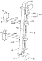
Fig. 1 is an axial view of the present embodiment, which mainly shows the overall structure of the assembled climbing frame for building;
FIG. 2 is a schematic view of the wall-attached support structure according to the present embodiment;
FIG. 3 is a schematic view of the roller set structure according to the present embodiment;
FIG. 4 is a schematic view of the auxiliary supporting device of this embodiment;
fig. 5 is a schematic view of the hook block and the elastic member structure according to this embodiment.
Reference numerals: 1. a main frame; 11. a unit frame; 12. a scaffold board; 13. a barrier net; 14. a slide rail; 141. a wheel groove; 15. a butting rod; 2. a wall-attached support; 21. a fixing plate; 3. supporting; 31. a hinged support; 32. adjusting the screw rod; 321. adjusting the nut; 33. a support head; 331. a card slot; 4. an auxiliary supporting device; 41. a mounting seat; 411. mounting a plate; 42. a rotating seat; 421. a chute; 43. a positive and negative rotation motor; 44. a clamping assembly; 441. a pressure-bearing support; 4411. a slider; 4412. a pressure bearing plate; 442. clamping the bracket; 443. a drive member; 4431. a drive motor; 4432. a lead screw; 5. a roller set; 51. a roller; 6. hooking the block; 7. mounting a shell; 71. an elastic member; 72. and stabilizing the bolt.
Detailed Description
The present application is described in further detail below with reference to the attached drawings.
The embodiment of the application discloses frame is climbed to assembled for building.
Referring to fig. 1 and 2, frame is climbed to assembled for building, including main frame 1 and install in building attach wall support 2, attach wall support 2 and correspond the both sides on main frame 1 length direction and be provided with two sets ofly in building, every group attaches wall support 2 and all includes a plurality of wall supports 2 that attach that set up at upper and lower interval, main frame 1 slides and connects in attaching wall support 2, it still is provided with the shore 3 that is used for supporting main frame 1 on wall support 2 to attach, the middle part of main frame 1 still is provided with the supplementary device 4 that props that is used for connecting building and main frame 1.
Specifically, referring to fig. 1 and 2, the main frame 1 includes a plurality of unit frames 11 sequentially arranged along a length direction thereof, and adjacent two unit frames 11 are locked by a fastener. Scaffold boards 12 are laid on the lower side in the main frame 1, the scaffold boards 12 are locked on the main frame 1 through fasteners, the scaffold boards 12 can be scaffold net boards, and one side, deviating from a construction building, of the main frame 1 is locked with a barrier net 13 through the fasteners. A slide rail 14 and an abutting rod 15 are fixed on one side of the main frame 1 close to the construction building. The slide rail 14 is vertical and locked on the main frame 1 through a fastener, and two ends of the slide rail 14 in the length direction of the main frame 1 are respectively provided with one slide rail. The pole 15 axes of butt joint sets up along the length direction of main frame 1, and butt joint pole 15 is fixed in on the slide rail 14 through the fastener, and butt joint pole 15 corresponds two slide rails 14 and is provided with two sets ofly, and every group butt joint pole 15 all includes along the even interval of vertical direction to be provided with a plurality of butt pole 15.
Referring to fig. 2 and 3, the structure and installation manner of each wall attachment support 2 are the same, and any one of the wall attachment supports 2 is explained as an example. The wall attaching support 2 is locked on the outer wall of the building through a fastener, and the roller group 5 is arranged on the wall attaching support 2. Attach and vertically be provided with fixed plate 21 on wall support 2, fixed plate 21 is provided with two along main frame 1 length direction interval on attaching wall support 2, roller train 5 is including two sets of gyro wheels 51, every gyro wheel 51 of group includes two gyro wheels 51, and two sets of gyro wheels 51 rotate respectively and install on two fixed plates 21, and, race 141 has all been seted up along slide rail 14 length direction to the both sides face of slide rail 14 on main frame 1 length direction, two sets of gyro wheels 51 imbed respectively in two race 141, thereby realize main frame 1 and attach the connection of sliding between the wall support 2. The top support 3 comprises a hinged support 31, an adjusting screw rod 32 and a support head 33, the hinged support 31 is hinged on the wall-attached support 2, the screw thread screwing directions of two sides of the adjusting screw rod 32 in the axial direction are opposite, two ends of the adjusting screw rod 32 are screwed into the hinged support 31 and the support head 33 respectively, and one side of the support head 33 departing from the adjusting screw rod 32 is provided with a clamping groove 331 for clamping the butt rod 15. In order to rotate the adjusting screw 32 conveniently, the adjusting nut 321 is sleeved in the middle of the adjusting screw 32, and the adjusting nut 321 is welded with the adjusting screw 32.
When the climbing frame is assembled, the main frame 1 is hoisted by a crane, so that two groups of rollers 51 of the roller group 5 on the wall-attached support 2 are correspondingly embedded into the roller grooves 141 of the slide rails 14; the main frame 1 can then be caused to slip relative to the wall attachment supports 2 under the control of the crane. After the main frame 1 slides to the predetermined position, the worker can rotate the top brace 3, so that the top brace 3 inclines upwards from the wall-attached support 2 to one side of the main frame 1, and rotate the adjusting screw 32, so that the support head 33 approaches to the corresponding abutting rod 15, and the abutting rod 15 is clamped into the clamping groove 331. So that the top brace 3 is pressed against the connection bar 15 and the main frame 1 is mounted on the wall attachment supports 2.
Next, referring to fig. 3 and 4, the secondary support device 4 includes a mounting seat 41 and a rotating seat 42. The mount pad 41 includes two mounting panels 411, and two mounting panels 411 all are the level, and two mounting panels 411 set up on main frame 1 along vertical direction interval, and two mounting panels 411 all are fixed in one side that main frame 1 is close to the building through the fastener. The rotating base 42 is located between the two mounting plates 411, the upper side and the lower side of the rotating base 42 are respectively abutted to the side walls of the two mounting plates 411 which are close to each other, and the upper side and the lower side of the rotating base 42 are rotatably connected to the corresponding mounting plates 411 through rotating shafts. Meanwhile, the mounting base 41 is also provided with a power component, the power component is a forward and reverse rotating motor 43, the forward and reverse rotating motor 43 is fixed on the mounting base 41, and an output shaft of the forward and reverse rotating motor 43 is coaxially fixed with a rotating shaft of the rotating base 42.
Referring to fig. 4 and 5, the secondary bracing apparatus 4 further includes a clamping assembly 44, and the clamping assembly 44 includes a bearing bracket 441, a clamping bracket 442, and a driving member 443. The pressure-bearing support 441 and the clamping support 442 are horizontally arranged and are parallel to each other, the pressure-bearing support 441 is located above the clamping support 442, one sides of the pressure-bearing support 441 and the clamping support 442 in the length direction are connected with the rotating seat 42 in a sliding mode, hook blocks 6 are arranged at the ends, away from the rotating seat 42, of the pressure-bearing support 441 and the clamping support 442, and the driving component 443 drives the pressure-bearing support 441 and the clamping support 442 to synchronously approach to and keep away from each other.
The sliding groove 421 is formed in the rotating seat 42 in the vertical direction, the sliding groove 421 penetrates through the rotating seat 42 along the length direction of the pressure bearing support 441, the pressure bearing support 441 and the clamping support 442 penetrate through the sliding groove 421 at the end departing from the hook block 6, the pressure bearing support 441 and the clamping support 442 both comprise sliding blocks 4411 departing from one side of the hook block 6, and the two sliding blocks 4411 are located in the sliding groove 421 and are in sliding fit with the sliding groove 421 in the vertical direction. In order to improve the pressure-bearing capacity of the pressure-bearing support 441 and the clamping support 442, pressure-bearing plates 4412 are fixed at the upper side position of the pressure-bearing support 441 and the lower side position of the clamping support 442, the two pressure-bearing plates 4412 are both located at one side of the rotating seat 42 close to the hook block 6, and the two pressure-bearing plates 4412 are both abutted against one side of the rotating seat 42 close to the hook block 6.
The two hook blocks 6 are symmetrical up and down on the pressure-bearing support 441 and the clamping support 442, and the hook blocks 6 on the pressure-bearing support 441 are taken as an example for explanation. Bearing support 441 deviates from the one end welding of rotating seat 42 and has installation shell 7, and the downside of installation shell 7 is opened, colludes piece 6 embedding installation shell 7 and with installation shell 7 cooperation of sliding. A pushing part is tightly propped between the inner top wall of the mounting shell 7 and the hook block 6, the pushing part is an elastic part 71, and the elastic part 71 in this embodiment is a compression spring. And, the side wall is provided with stabilizing bolt 72 on installing shell 7 from the top down run through installing shell 7, and stabilizing bolt 72's screw rod and installing shell 7 go up the side wall and slide along vertical direction and be connected, and stabilizing bolt 72 stretches into the one end screw thread screw in piece 6 in installing shell 7, and elastic component 71 overlaps and establishes stabilizing bolt 72.
The mounting shell 7, the elastic piece 71 and the stabilizing bolt 72 are correspondingly arranged at one end of the clamping bracket 442, which is far away from the rotating seat 42, and are symmetrical relative to the mounting shell 7, the elastic piece 71 and the stabilizing bolt 72 on the pressure bearing bracket 441, so that the hook block 6 on the clamping bracket 442 can be normally used.
The driving part 443 includes a driving motor 4431 and a lead screw 4432. The lead screw 4432 is vertical, the lead screw 4432 is rotatably mounted on the rotating base 42, and the lead screw 4432 is positioned on one side of the rotating base 42, which is far away from the hook block 6. The screw thread turning directions of the two axial sides of the screw 4432 are opposite, the two sides of the screw 4432 penetrate through the pressure bearing bracket 441 and the clamping bracket 442 respectively, and the two sides of the screw 4432 are in threaded fit with the pressure bearing bracket 441 and the clamping bracket 442 respectively. The driving motor 4431 is fixed on the rotating base 42, and an output shaft of the driving motor 4431 is coaxially fixed with the lead screw 4432.
After the top brace 3 tightly props up the abutting rod 15 on the main frame 1, the forward and reverse rotating motor 43 drives the rotating seat 42 to rotate, and the pressure-bearing bracket 441 and the clamping bracket 442 face one side of the building, so that the pressure-bearing bracket 441 is positioned at the upper side of a corresponding floor of the building, and the clamping bracket 442 is positioned at the lower side of the corresponding floor of the building; then, the driving motor 4431 drives the screw 4432 to rotate, and the bearing bracket 441 and the clamping bracket 442 approach each other and clamp the corresponding floor of the building. When the side walls are poured or built on the upper edge and the lower edge of the corresponding building layer, the two hook blocks 6 are in an extending state and hook the side walls of the corresponding building layer under the action of the elastic pieces 71; when there is not the side wall on the building corresponding floor, two colluding blocks 6 butt building corresponding floor, two colluding blocks 6 will compress two elastic component 71 respectively, and two colluding blocks 6 will retract respectively in two installation shell 7.
In addition, it should be noted that all the fasteners related to the present embodiment may adopt any one of a bolt, a bolt and a nut, and the like, so as to achieve stable locking of the corresponding parts, and the structure is simple and is not shown in the drawings.
The embodiment of the application also discloses a using method of the assembled climbing frame for the building.
Referring to fig. 1, the method for using the assembled climbing frame for the building comprises the following steps:
s1, splicing the main frame 1.
The unit frames 11 are assembled into the main frame 1 through fasteners, the scaffold boards 12 are laid on the lower side of the main frame 1 through the fasteners, the barrier net 13 is locked on one side of the main frame 1 departing from a building through the fasteners, and the main frame 1 is provided with the sliding rails 14 and the abutting rods 15 close to one side of the building. At the same time, the mounting base 41 and the rotating base 42 are mounted at the middle position in the longitudinal direction of the main frame 1, and the pressure receiving bracket 441, the clamp bracket 442, and the driving member 443 are mounted on the rotating base 42.
And S2, mounting a wall attaching support 2.
Referring to fig. 2 and 3, the wall-attached support 2 is locked to the outer wall of the building through a fastener, two sets of wall-attached supports 2 are installed corresponding to two sides of the main frame 1 in the length direction, and each set of wall-attached supports 2 includes a plurality of wall-attached supports 2 arranged at intervals from top to bottom. Wherein, each wall-attached support 2 is provided with a roller group 5 and a top support 3.
And S3, assembling.
Referring to fig. 1, a crane is used to hoist the main frame 1, so that two groups of rollers 51 of the roller group 5 on the wall-attached support 2 are correspondingly embedded into the roller grooves 141 of the slide rails 14; then, under the control of the crane, the main frame 1 can be made to slide relative to the wall attachment supports 2. After the main frame 1 reaches a predetermined position, the top brace 3 is rotated, so that the top brace 3 inclines upwards from the wall-attached support 2 to one side of the main frame 1, the adjusting screw 32 is rotated, the support head 33 is close to the corresponding abutting rod 15, and the abutting rod 15 is clamped into the clamping groove 331. And then, sequentially hoisting other main frames 1 above the lowermost main frame 1 in the same manner, and fixedly connecting the two vertically adjacent main frames 1.
And S4, reinforcing.
Referring to fig. 4 and 5, the forward and reverse rotation motor 43 drives the rotating base 42 to rotate, and the pressure-bearing bracket 441 and the clamping bracket 442 face one side of the building, so that the pressure-bearing bracket 441 is positioned at the upper side of the corresponding floor of the building, and the clamping bracket 442 is positioned at the lower side of the corresponding floor of the building; then, the driving motor 4431 drives the screw 4432 to rotate, the bearing bracket 441 and the clamping bracket 442 approach each other and clamp the corresponding floor of the building, and thus the basic installation of the climbing frame is completed.
When the side walls are poured or built on the edges above and below the corresponding building layer, the two hook blocks 6 are in an extending state and hook the side walls of the corresponding building layer under the action of the elastic pieces 71. When there is not the side wall on the building corresponding floor, two hook blocks 6 butt building corresponding floor, and two hook blocks 6 will compress two elastic component 71 respectively, and two hook blocks 6 will retract respectively in two installation shell 7.
The above embodiments are preferred embodiments of the present application, and the protection scope of the present application is not limited by the above embodiments, so: all equivalent changes made according to the structure, shape and principle of the present application shall be covered by the protection scope of the present application.
Claims (10)
1. The utility model provides a frame is climbed to assembled for building, includes main frame (1) and installs attaches wall support (2) on building, main frame (1) with attach wall support (2) and slide and be connected, attach wall support (2) and respectively be provided with a set of, its characterized in that in main frame (1) length direction's both sides: the mounting seat (41) is detachably fixed at the middle position of the main frame (1) in the length direction, the mounting seat (41) is provided with a pressure bearing support (441) in a lifting mode, the pressure bearing support (441) is horizontal and extends towards one side of a building, and a driving component (443) used for driving the pressure bearing support (441) to move up and down is further arranged on the mounting seat (41).
2. The assembled climbing frame for building of claim 1, wherein: the mounting seat (41) is provided with a rotating seat (42) in a rotating mode around a vertical axis, the pressure bearing support (441) is arranged on the rotating seat (42) in a lifting mode, and a power component used for driving the rotating seat (42) to rotate is further arranged on the mounting seat (41).
3. The assembled climbing frame for building of claim 2, wherein: the rotating seat (42) is provided with a clamping bracket (442) in a lifting mode at the lower side of the pressure-bearing bracket (441), the clamping bracket (442) is parallel to the pressure-bearing bracket (441), and the driving part (443) drives the pressure-bearing bracket (441) and the clamping bracket (442) to synchronously approach and separate.
4. The assembled climbing frame for building of claim 2, wherein: a sliding groove (421) is formed in the rotating seat (42) along the vertical direction, and the pressure-bearing support (441) is embedded into the sliding groove (421) on one side of the rotating seat (42) and is in sliding fit with the sliding groove (421) along the vertical direction; and a pressure bearing plate (4412) is fixed at the upper side position of the middle part of the pressure bearing bracket (441), and the pressure bearing plate (4412) is abutted against one side surface of the rotating seat (42) close to the pressure bearing plate (4412).
5. The assembled climbing frame for building of claim 4, wherein: the sliding groove (421) penetrates through the rotating seat (42) along the length direction of the pressure-bearing support (441), the pressure-bearing support (441) penetrates through the sliding groove (421) on one side of the rotating seat (42), the driving component (443) comprises a lead screw (4432), the lead screw (4432) is vertical, the lead screw (4432) is rotatably erected on the rotating seat (42) around the axis of the lead screw, and the lead screw (4432) penetrates through one end, deviating from a building, of the pressure-bearing support (441) and is in threaded fit with the pressure-bearing support (441).
6. The assembled climbing frame for building according to claim 1, wherein: and one end of the pressure-bearing support (441), which is far away from the rotating seat (42), is provided with a hook block (6) in a lifting manner, and the pressure-bearing support (441) is also provided with a pushing piece for driving the hook block (6) to move downwards.
7. The assembled climbing frame for building of claim 6, wherein: the bearing support (441) is fixedly provided with an installation shell (7) on one side departing from the rotating seat (42), the lower side of the installation shell (7) is open, and the hook block (6) is embedded into the installation shell (7) and is in sliding fit with the installation shell (7).
8. The assembled climbing frame for building of claim 7, wherein: the pushing piece is an elastic piece (71), and the elastic piece (71) is tightly propped against between the hook block (6) and the inner wall of the mounting shell (7) and provides downward thrust for the hook block (6).
9. The assembled climbing frame for building and the use method thereof according to claim 8, wherein: a stabilizing bolt (72) penetrates through the upper side wall of the mounting shell (7) from top to bottom above the mounting shell (7), a screw rod of the stabilizing bolt (72) is connected with the upper side wall of the mounting shell (7) in a sliding manner along the vertical direction, and one end of the stabilizing bolt (72) extending into the mounting shell (7) is screwed into the hook block (6) through threads;
the stabilizing bolt (72) penetrates through the elastic member (71).
10. The use method of the assembled climbing frame for the building is characterized in that: the method comprises the following steps:
splicing the main frame (1), assembling the unit frames (11) into the main frame (1), fixing an installation seat (41) at the middle position of the main frame (1) in the length direction, and installing a pressure bearing bracket (441) and a driving component (443) on the installation seat (41);
installing wall attaching supports (2), installing the wall attaching supports (2) on an outer wall of a building, installing two groups of wall attaching supports (2) corresponding to two sides of the main frame (1) in the length direction, wherein the two groups of wall attaching supports (2) respectively comprise a plurality of wall attaching supports (2) arranged at intervals up and down;
assembling, namely sequentially hoisting a plurality of main frames (1) to enable the main frames (1) to be connected with the wall attaching support (2) in a sliding manner, and after the main frames (1) reach a preset position, tightly propping rods (15) on the main frames (1) against the top braces (3) on the wall attaching support (2) and fixedly connecting the two vertically adjacent main frames (1);
and (3) reinforcing, wherein the pressure-bearing support (441) is driven to descend by the driving part (443), so that the pressure-bearing support (441) is abutted against the upper side surface of the corresponding floor of the building.
Priority Applications (1)
| Application Number | Priority Date | Filing Date | Title |
|---|---|---|---|
| CN202211071794.1A CN115370118B (en) | 2022-09-02 | 2022-09-02 | Assembled climbing frame for building and application method thereof |
Applications Claiming Priority (1)
| Application Number | Priority Date | Filing Date | Title |
|---|---|---|---|
| CN202211071794.1A CN115370118B (en) | 2022-09-02 | 2022-09-02 | Assembled climbing frame for building and application method thereof |
Publications (2)
| Publication Number | Publication Date |
|---|---|
| CN115370118A true CN115370118A (en) | 2022-11-22 |
| CN115370118B CN115370118B (en) | 2023-10-27 |
Family
ID=84069924
Family Applications (1)
| Application Number | Title | Priority Date | Filing Date |
|---|---|---|---|
| CN202211071794.1A Active CN115370118B (en) | 2022-09-02 | 2022-09-02 | Assembled climbing frame for building and application method thereof |
Country Status (1)
| Country | Link |
|---|---|
| CN (1) | CN115370118B (en) |
Citations (9)
| Publication number | Priority date | Publication date | Assignee | Title |
|---|---|---|---|---|
| US20040200178A1 (en) * | 2003-04-08 | 2004-10-14 | Simmons Robert J. | Matrix frame/panel skin building structure |
| US20150167326A1 (en) * | 2013-12-17 | 2015-06-18 | Shenzhen Techen Technology Co., Ltd | Sealed and integrated climbing scaffold and method for using the same |
| CN211736326U (en) * | 2020-01-13 | 2020-10-23 | 通州建总集团有限公司 | Fabricated outer wall climbing frame for building construction |
| CN213894834U (en) * | 2020-12-16 | 2021-08-06 | 广州市芳村建筑工程有限公司 | A Truss Bridge Based on Attached Lifting Platform |
| CN113356551A (en) * | 2021-06-16 | 2021-09-07 | 重庆渝能建筑安装工程有限公司 | Cantilever frame structure |
| US20210293037A1 (en) * | 2018-07-23 | 2021-09-23 | Peri Gmbh | Lift drive for a rail-guided climbing system |
| CN114382274A (en) * | 2022-01-25 | 2022-04-22 | 段艳红 | Intelligent climbing frame system for construction site |
| CN114704068A (en) * | 2022-06-07 | 2022-07-05 | 中铁城建集团第一工程有限公司 | Attached lifting scaffold system |
| CN114856159A (en) * | 2022-04-22 | 2022-08-05 | 江苏正方园建设集团有限公司 | Temporary attachment device for attached lifting scaffold |
-
2022
- 2022-09-02 CN CN202211071794.1A patent/CN115370118B/en active Active
Patent Citations (9)
| Publication number | Priority date | Publication date | Assignee | Title |
|---|---|---|---|---|
| US20040200178A1 (en) * | 2003-04-08 | 2004-10-14 | Simmons Robert J. | Matrix frame/panel skin building structure |
| US20150167326A1 (en) * | 2013-12-17 | 2015-06-18 | Shenzhen Techen Technology Co., Ltd | Sealed and integrated climbing scaffold and method for using the same |
| US20210293037A1 (en) * | 2018-07-23 | 2021-09-23 | Peri Gmbh | Lift drive for a rail-guided climbing system |
| CN211736326U (en) * | 2020-01-13 | 2020-10-23 | 通州建总集团有限公司 | Fabricated outer wall climbing frame for building construction |
| CN213894834U (en) * | 2020-12-16 | 2021-08-06 | 广州市芳村建筑工程有限公司 | A Truss Bridge Based on Attached Lifting Platform |
| CN113356551A (en) * | 2021-06-16 | 2021-09-07 | 重庆渝能建筑安装工程有限公司 | Cantilever frame structure |
| CN114382274A (en) * | 2022-01-25 | 2022-04-22 | 段艳红 | Intelligent climbing frame system for construction site |
| CN114856159A (en) * | 2022-04-22 | 2022-08-05 | 江苏正方园建设集团有限公司 | Temporary attachment device for attached lifting scaffold |
| CN114704068A (en) * | 2022-06-07 | 2022-07-05 | 中铁城建集团第一工程有限公司 | Attached lifting scaffold system |
Non-Patent Citations (1)
| Title |
|---|
| 刘鑫;: "装配式建筑施工中的导架式升降平台附着技术研究", 建筑施工, no. 05 * |
Also Published As
| Publication number | Publication date |
|---|---|
| CN115370118B (en) | 2023-10-27 |
Similar Documents
| Publication | Publication Date | Title |
|---|---|---|
| CN103422663B (en) | Attached lift scaffold | |
| CN114086772B (en) | Installation and construction method of herringbone steel truss | |
| CN110820787A (en) | Precast concrete butt joint system | |
| CN1912314A (en) | Automatic hydraulic climbing shuttering | |
| CN111395184A (en) | System and method for constructing high pier with gradually-changed section by using electric bridge type scaffold platform | |
| CN214169903U (en) | Hydraulic jacking climbing mold mechanism | |
| CN113235904B (en) | Circulating mutual climbing lifting column and using method thereof | |
| CN112173917B (en) | Large-span steel structure sliding device and construction method thereof | |
| CN115370118B (en) | Assembled climbing frame for building and application method thereof | |
| CN111764667A (en) | Steel structure truss installation construction equipment and installation construction method | |
| CN114109010B (en) | Hydraulic adjustable lifting structure based on steel pipe scaffold | |
| CN116838112A (en) | Safety sliding equipment and method for building steel structure | |
| CN214658688U (en) | Efficient creeping formwork equipment for variable cross-section creeping formwork construction | |
| CN215407312U (en) | Overhanging climbing device | |
| CN212359071U (en) | A lifting operation platform for the construction of the decorative surface layer of the inclined column | |
| CN210342627U (en) | Connecting structure for preventing falling and protective frame | |
| CN210342629U (en) | Protection frame and lifting structure thereof | |
| CN210342628U (en) | Protective frame | |
| CN116607734A (en) | Building assembly operation platform capable of ascending and descending step by step | |
| CN120573611B (en) | Top lifting device of tower crane and quick assembly disassembly structure thereof | |
| CN213710277U (en) | Liftable handling frame | |
| CN224173748U (en) | An ALC partition wall panel installation device | |
| CN222009561U (en) | A lifting scaffolding wall support extension piece connection structure | |
| CN214527518U (en) | Traction type construction elevator synchronously lifted with building machine | |
| CN223073886U (en) | Manual slide pile manned automatic slide device is resisted in plain type |
Legal Events
| Date | Code | Title | Description |
|---|---|---|---|
| PB01 | Publication | ||
| PB01 | Publication | ||
| SE01 | Entry into force of request for substantive examination | ||
| SE01 | Entry into force of request for substantive examination | ||
| GR01 | Patent grant | ||
| GR01 | Patent grant |