CN115355295A - Transmission chain of wind generating set, wind generating set and single-blade barring method - Google Patents
Transmission chain of wind generating set, wind generating set and single-blade barring method Download PDFInfo
- Publication number
- CN115355295A CN115355295A CN202210981213.1A CN202210981213A CN115355295A CN 115355295 A CN115355295 A CN 115355295A CN 202210981213 A CN202210981213 A CN 202210981213A CN 115355295 A CN115355295 A CN 115355295A
- Authority
- CN
- China
- Prior art keywords
- speed
- regulating
- planetary
- gearbox
- wind
- Prior art date
- Legal status (The legal status is an assumption and is not a legal conclusion. Google has not performed a legal analysis and makes no representation as to the accuracy of the status listed.)
- Pending
Links
Images



Classifications
-
- F—MECHANICAL ENGINEERING; LIGHTING; HEATING; WEAPONS; BLASTING
- F16—ENGINEERING ELEMENTS AND UNITS; GENERAL MEASURES FOR PRODUCING AND MAINTAINING EFFECTIVE FUNCTIONING OF MACHINES OR INSTALLATIONS; THERMAL INSULATION IN GENERAL
- F16H—GEARING
- F16H37/00—Combinations of mechanical gearings, not provided for in groups F16H1/00 - F16H35/00
- F16H37/12—Gearings comprising primarily toothed or friction gearing, links or levers, and cams, or members of at least two of these types
- F16H37/124—Gearings comprising primarily toothed or friction gearing, links or levers, and cams, or members of at least two of these types for interconverting rotary motion and reciprocating motion
-
- F—MECHANICAL ENGINEERING; LIGHTING; HEATING; WEAPONS; BLASTING
- F03—MACHINES OR ENGINES FOR LIQUIDS; WIND, SPRING, OR WEIGHT MOTORS; PRODUCING MECHANICAL POWER OR A REACTIVE PROPULSIVE THRUST, NOT OTHERWISE PROVIDED FOR
- F03D—WIND MOTORS
- F03D13/00—Assembly, mounting or commissioning of wind motors; Arrangements specially adapted for transporting wind motor components
- F03D13/10—Assembly of wind motors; Arrangements for erecting wind motors
-
- F—MECHANICAL ENGINEERING; LIGHTING; HEATING; WEAPONS; BLASTING
- F03—MACHINES OR ENGINES FOR LIQUIDS; WIND, SPRING, OR WEIGHT MOTORS; PRODUCING MECHANICAL POWER OR A REACTIVE PROPULSIVE THRUST, NOT OTHERWISE PROVIDED FOR
- F03D—WIND MOTORS
- F03D15/00—Transmission of mechanical power
-
- F—MECHANICAL ENGINEERING; LIGHTING; HEATING; WEAPONS; BLASTING
- F03—MACHINES OR ENGINES FOR LIQUIDS; WIND, SPRING, OR WEIGHT MOTORS; PRODUCING MECHANICAL POWER OR A REACTIVE PROPULSIVE THRUST, NOT OTHERWISE PROVIDED FOR
- F03D—WIND MOTORS
- F03D7/00—Controlling wind motors
- F03D7/02—Controlling wind motors the wind motors having rotation axis substantially parallel to the air flow entering the rotor
- F03D7/0244—Controlling wind motors the wind motors having rotation axis substantially parallel to the air flow entering the rotor for braking
-
- F—MECHANICAL ENGINEERING; LIGHTING; HEATING; WEAPONS; BLASTING
- F03—MACHINES OR ENGINES FOR LIQUIDS; WIND, SPRING, OR WEIGHT MOTORS; PRODUCING MECHANICAL POWER OR A REACTIVE PROPULSIVE THRUST, NOT OTHERWISE PROVIDED FOR
- F03D—WIND MOTORS
- F03D9/00—Adaptations of wind motors for special use; Combinations of wind motors with apparatus driven thereby; Wind motors specially adapted for installation in particular locations
- F03D9/20—Wind motors characterised by the driven apparatus
- F03D9/25—Wind motors characterised by the driven apparatus the apparatus being an electrical generator
- F03D9/255—Wind motors characterised by the driven apparatus the apparatus being an electrical generator connected to electrical distribution networks; Arrangements therefor
-
- F—MECHANICAL ENGINEERING; LIGHTING; HEATING; WEAPONS; BLASTING
- F16—ENGINEERING ELEMENTS AND UNITS; GENERAL MEASURES FOR PRODUCING AND MAINTAINING EFFECTIVE FUNCTIONING OF MACHINES OR INSTALLATIONS; THERMAL INSULATION IN GENERAL
- F16H—GEARING
- F16H48/00—Differential gearings
- F16H48/06—Differential gearings with gears having orbital motion
-
- F—MECHANICAL ENGINEERING; LIGHTING; HEATING; WEAPONS; BLASTING
- F16—ENGINEERING ELEMENTS AND UNITS; GENERAL MEASURES FOR PRODUCING AND MAINTAINING EFFECTIVE FUNCTIONING OF MACHINES OR INSTALLATIONS; THERMAL INSULATION IN GENERAL
- F16H—GEARING
- F16H57/00—General details of gearing
- F16H57/02—Gearboxes; Mounting gearing therein
-
- F—MECHANICAL ENGINEERING; LIGHTING; HEATING; WEAPONS; BLASTING
- F16—ENGINEERING ELEMENTS AND UNITS; GENERAL MEASURES FOR PRODUCING AND MAINTAINING EFFECTIVE FUNCTIONING OF MACHINES OR INSTALLATIONS; THERMAL INSULATION IN GENERAL
- F16H—GEARING
- F16H57/00—General details of gearing
- F16H57/02—Gearboxes; Mounting gearing therein
- F16H57/035—Gearboxes for gearing with endless flexible members
-
- F—MECHANICAL ENGINEERING; LIGHTING; HEATING; WEAPONS; BLASTING
- F16—ENGINEERING ELEMENTS AND UNITS; GENERAL MEASURES FOR PRODUCING AND MAINTAINING EFFECTIVE FUNCTIONING OF MACHINES OR INSTALLATIONS; THERMAL INSULATION IN GENERAL
- F16H—GEARING
- F16H57/00—General details of gearing
- F16H57/02—Gearboxes; Mounting gearing therein
- F16H57/037—Gearboxes for accommodating differential gearings
-
- F—MECHANICAL ENGINEERING; LIGHTING; HEATING; WEAPONS; BLASTING
- F16—ENGINEERING ELEMENTS AND UNITS; GENERAL MEASURES FOR PRODUCING AND MAINTAINING EFFECTIVE FUNCTIONING OF MACHINES OR INSTALLATIONS; THERMAL INSULATION IN GENERAL
- F16H—GEARING
- F16H57/00—General details of gearing
- F16H57/08—General details of gearing of gearings with members having orbital motion
-
- F—MECHANICAL ENGINEERING; LIGHTING; HEATING; WEAPONS; BLASTING
- F16—ENGINEERING ELEMENTS AND UNITS; GENERAL MEASURES FOR PRODUCING AND MAINTAINING EFFECTIVE FUNCTIONING OF MACHINES OR INSTALLATIONS; THERMAL INSULATION IN GENERAL
- F16H—GEARING
- F16H57/00—General details of gearing
- F16H57/02—Gearboxes; Mounting gearing therein
- F16H2057/02034—Gearboxes combined or connected with electric machines
-
- F—MECHANICAL ENGINEERING; LIGHTING; HEATING; WEAPONS; BLASTING
- F16—ENGINEERING ELEMENTS AND UNITS; GENERAL MEASURES FOR PRODUCING AND MAINTAINING EFFECTIVE FUNCTIONING OF MACHINES OR INSTALLATIONS; THERMAL INSULATION IN GENERAL
- F16H—GEARING
- F16H57/00—General details of gearing
- F16H57/02—Gearboxes; Mounting gearing therein
- F16H2057/02039—Gearboxes for particular applications
- F16H2057/02078—Gearboxes for particular applications for wind turbines
-
- Y—GENERAL TAGGING OF NEW TECHNOLOGICAL DEVELOPMENTS; GENERAL TAGGING OF CROSS-SECTIONAL TECHNOLOGIES SPANNING OVER SEVERAL SECTIONS OF THE IPC; TECHNICAL SUBJECTS COVERED BY FORMER USPC CROSS-REFERENCE ART COLLECTIONS [XRACs] AND DIGESTS
- Y02—TECHNOLOGIES OR APPLICATIONS FOR MITIGATION OR ADAPTATION AGAINST CLIMATE CHANGE
- Y02E—REDUCTION OF GREENHOUSE GAS [GHG] EMISSIONS, RELATED TO ENERGY GENERATION, TRANSMISSION OR DISTRIBUTION
- Y02E10/00—Energy generation through renewable energy sources
- Y02E10/70—Wind energy
- Y02E10/72—Wind turbines with rotation axis in wind direction
Landscapes
- Engineering & Computer Science (AREA)
- General Engineering & Computer Science (AREA)
- Mechanical Engineering (AREA)
- Life Sciences & Earth Sciences (AREA)
- Sustainable Development (AREA)
- Sustainable Energy (AREA)
- Chemical & Material Sciences (AREA)
- Combustion & Propulsion (AREA)
- Power Engineering (AREA)
- Wind Motors (AREA)
Abstract
本发明提供一种风力发电机组的传动链、风力发电机组及单叶片盘车方法,属于风力发电技术领域。风力发电机组的传动链包括差动行星调速齿轮箱、同步发电机和调速电机,差动行星调速齿轮箱具有第一输入端和第二输入端,第一输入端用于与风力发电机组的风轮连接,第二输入端用于与调速电机的输出端连接,差动行星调速齿轮箱的输出端与同步发电机的输入端连接,调速电机和同步发电机均位于差动行星调速齿轮箱远离风轮的一侧。整个传动链的结构更加紧凑,布局更加合理,同时为适用不同的风轮直径,可以在传动链与风轮之间布置不同级数齿轮传动的齿轮箱,提高了传动链的适配性,扩大了传动链的应用范围。

The invention provides a transmission chain of a wind power generator set, a wind power generator set and a single-blade turning method, belonging to the technical field of wind power generation. The transmission chain of the wind power generating set includes a differential planetary speed-regulating gearbox, a synchronous generator and a speed-regulating motor. The differential planetary speed-regulating gearbox has a first input end and a second input end. The wind wheel of the unit is connected, the second input end is used to connect with the output end of the speed-regulating motor, the output end of the differential planetary speed-regulating gearbox is connected with the input end of the synchronous generator, and the speed-regulating motor and the synchronous generator are both located in the differential The side of the dynamic planetary speed-regulating gearbox away from the wind wheel. The structure of the entire transmission chain is more compact and the layout is more reasonable. At the same time, in order to adapt to different diameters of wind wheels, gear boxes with different stages of gear transmission can be arranged between the transmission chain and the wind wheel, which improves the adaptability of the transmission chain and expands The scope of application of the transmission chain.
Description
技术领域technical field
本发明涉及风力发电技术领域,特别涉及一种风力发电机组的传动链、风力发电机组及单叶片盘车方法。The invention relates to the technical field of wind power generation, in particular to a transmission chain of a wind power generator, a wind power generator and a single-blade turning method.
背景技术Background technique
风力发电机机组主要有双馈型、半直驱型及直驱型三种型式,然而三种型式的风力发电机机组都需要采用大功率的变流器实现并网,成本较高。现有技术中,已有一些技术手段能够实现同步发电机的直接并网。比如,中国专利CN202215429U公开了一种差动齿箱调速型同步风力发电机组的控制系统,该系统通过在三级齿轮箱的输出端增加齿轮箱差动式输出级,使得同步发电机发出的电可以直接并入电网。其采用的三级齿轮箱为两级行星加一级平行轴齿轮,一级平行轴齿轮具有凸出于两级行星的小齿轮,方便在齿轮箱差动式输出级的两侧分别设置伺服电机和常规同步发电机,然而上述结构布局具有特定的应用范围,对于其他没有凸出小齿轮的齿轮箱,上述结构布局不再适用。There are mainly three types of wind turbines: doubly-fed, semi-direct drive and direct drive. However, all three types of wind turbines need to use high-power converters to realize grid connection, which is costly. In the prior art, there are some technical means that can realize direct grid connection of synchronous generators. For example, the Chinese patent CN202215429U discloses a control system of a synchronous wind turbine generator with differential gearbox speed regulation. Electricity can be directly connected to the grid. The three-stage gearbox it adopts is two-stage planetary plus one-stage parallel-shaft gear, and the first-stage parallel-shaft gear has a pinion protruding from the two-stage planet, so that it is convenient to install servo motors on both sides of the differential output stage of the gearbox Compared with conventional synchronous generators, however, the above-mentioned structural layout has a specific application range, and for other gearboxes without protruding pinions, the above-mentioned structural layout is no longer applicable.
发明内容Contents of the invention
本发明要解决的技术问题是为了解决现有技术中风力发电机组的传动链中的伺服电机和常规同步发电机设置在齿轮箱差动式输出级的两侧导致的结构布局局限性较大,不适用于其他类型齿轮箱的缺陷,提供一种风力发电机组的传动链、风力发电机组及单叶片盘车方法。The technical problem to be solved by the present invention is to solve the relatively large structural layout limitations caused by the arrangement of the servo motor and the conventional synchronous generator in the transmission chain of the wind power generating set on both sides of the gearbox differential output stage in the prior art, The invention is not applicable to the defects of other types of gearboxes, and provides a transmission chain of a wind power generating set, a wind generating set and a single-blade turning method.
本发明通过下述技术方案来解决上述技术问题:The present invention solves the above technical problems through the following technical solutions:
一种风力发电机组的传动链,包括差动行星调速齿轮箱、同步发电机和调速电机,所述差动行星调速齿轮箱具有第一输入端和第二输入端,所述第一输入端用于与所述风力发电机组的风轮连接,所述第二输入端用于与所述调速电机的输出端连接,所述差动行星调速齿轮箱的输出端与所述同步发电机的输入端连接,所述调速电机和所述同步发电机均位于所述差动行星调速齿轮箱远离所述风轮的一侧。A transmission chain of a wind power generating set, comprising a differential planetary speed-regulating gearbox, a synchronous generator and a speed-regulating motor, the differential planetary speed-regulating gearbox has a first input end and a second input end, the first The input end is used to connect with the wind rotor of the wind power generating set, the second input end is used to connect with the output end of the speed-regulating motor, and the output end of the differential planetary speed-regulating gearbox is synchronized with the The input end of the generator is connected, and both the speed-regulating motor and the synchronous generator are located on the side of the differential planetary speed-regulating gearbox away from the wind wheel.
在本方案中,差动行星调速齿轮箱具有两个输入端,即第一输入端和第二输入端,第一输入端与风轮连接,通过风轮将自然环境中的风能转化为机械能,获得初始动力;第二输入端与调速电机连接,由于风力是不稳定的,即初始动力是不稳定的,通过调速电机可以调节差动行星调速齿轮箱的输出端的转速,并使得该转速恒定,进而使得与差动行星调速齿轮箱的输出端相连接的同步发电机的转子的转速恒定,同步发电机输出的电频率恒定,可以直接或通过第二变压器并入电网。调速电机和同步发电机均位于差动行星调速齿轮箱远离风轮的一侧,使得整个传动链的结构更加紧凑,布局更加合理,为适用不同的风轮直径,可以在传动链与风轮之间布置不同级数齿轮传动的齿轮箱,提高了传动链的适配性,扩大了传动链的应用范围。In this scheme, the differential planetary speed-regulating gearbox has two input ends, namely the first input end and the second input end, the first input end is connected with the wind wheel, and the wind energy in the natural environment is converted into mechanical energy through the wind wheel , to obtain the initial power; the second input end is connected to the speed-regulating motor, because the wind force is unstable, that is, the initial power is unstable, the speed-regulating motor can adjust the speed of the output end of the differential planetary speed-regulating gearbox, and make The rotation speed is constant, which in turn makes the rotation speed of the rotor of the synchronous generator connected to the output end of the differential planetary speed-regulating gearbox constant, and the electrical frequency output by the synchronous generator is constant, which can be connected to the grid directly or through the second transformer. Both the speed-regulating motor and the synchronous generator are located on the side away from the wind wheel of the differential planetary speed-regulating gearbox, which makes the structure of the entire transmission chain more compact and the layout more reasonable. Gear boxes with different stages of gear transmission are arranged between the wheels, which improves the adaptability of the transmission chain and expands the application range of the transmission chain.
优选地,所述差动行星调速齿轮箱包括齿圈和调速太阳轮,所述齿圈的输出轴与所述同步发电机连接,所述调速太阳轮的输入轴为所述第二输入端,所述调速太阳轮的输入轴与所述调速电机的输出端连接。Preferably, the differential planetary speed-regulating gearbox includes a ring gear and a speed-regulating sun gear, the output shaft of the ring gear is connected to the synchronous generator, and the input shaft of the speed-regulating sun gear is the second At the input end, the input shaft of the speed-regulating sun gear is connected with the output end of the speed-regulating motor.
在本方案中,齿圈的输出轴为差动行星调速齿轮箱的输出端,调速太阳轮的输入轴为差动行星调速齿轮箱的第二输入端,调速电机用于驱动调速太阳轮转动,进而通过调节行星轮的转动来调节齿圈的转动,使得齿圈的转速达到恒定的预设值,使得同步发电机输出的电频率恒定,可以直接或通过第二变压器并入电网。In this scheme, the output shaft of the ring gear is the output end of the differential planetary speed-regulating gearbox, the input shaft of the speed-regulating sun gear is the second input end of the differential planetary speed-regulating gearbox, and the speed-regulating motor is used to drive the speed-regulating The sun gear rotates at a high speed, and then the rotation of the ring gear is adjusted by adjusting the rotation of the planetary gear, so that the rotation speed of the ring gear reaches a constant preset value, so that the electric frequency output by the synchronous generator is constant, which can be incorporated directly or through the second transformer power grid.
优选地,所述调速太阳轮设于所述齿圈的内圈,所述齿圈的输出轴为空心轴,所述调速太阳轮的输入轴穿过所述齿圈的输出轴与所述调速电机的输出端连接。Preferably, the speed-adjusting sun gear is arranged on the inner ring of the ring gear, the output shaft of the ring gear is a hollow shaft, and the input shaft of the speed-regulating sun gear passes through the output shaft of the ring gear and the Connect the output terminal of the speed-regulating motor.
在本方案中,调速太阳轮位于齿圈的内圈,调速太阳轮的输入轴穿过齿圈的空心输出轴,即齿圈的输出轴套设于调速太阳轮的输入轴外侧,使得差动行星调速齿轮箱的结构更加紧凑,减少空间占用,且方便齿圈的输出轴连接的同步发电机和调速太阳轮的输入轴连接的调速电机设置于差动行星调速齿轮箱的同一侧。In this scheme, the speed-regulating sun gear is located in the inner ring of the ring gear, and the input shaft of the speed-regulating sun gear passes through the hollow output shaft of the ring gear, that is, the output shaft of the ring gear is sleeved outside the input shaft of the speed-regulating sun gear. Make the structure of the differential planetary speed-regulating gearbox more compact, reduce space occupation, and facilitate the synchronous generator connected to the output shaft of the ring gear and the speed-regulating motor connected to the input shaft of the speed-regulating sun gear to be arranged on the differential planetary speed-regulating gear same side of the box.
优选地,所述差动行星调速齿轮箱还包括行星架和行星轮,所述行星架的输入轴为所述第一输入端,所述行星架驱动所述行星轮公转,所述行星轮位于所述调速太阳轮和齿圈之间并与所述调速太阳轮和所述齿圈啮合连接。Preferably, the differential planetary speed-regulating gearbox further includes a planetary carrier and a planetary gear, the input shaft of the planetary carrier is the first input end, the planetary carrier drives the planetary wheel to revolve, and the planetary wheel It is located between the speed-regulating sun gear and the ring gear and meshedly connected with the speed-regulating sun gear and the ring gear.
在本方案中,行星架的输入轴为第一输入端,方便与风轮进行直接或间接的连接;行星架用于驱动行星轮公转,调速太阳轮与行星轮啮合,使得行星轮在受到来自风轮的初始动力驱动的同时,还受到来自调速电机的调节动力的调节,进而使得与其啮合的齿圈的转速达到恒定的预设值,即使与齿圈连接的同步发电机转子的转速达到恒定的预设值,输出的电频率恒定,可以直接或通过第二变压器并入电网。In this scheme, the input shaft of the planetary carrier is the first input end, which is convenient for direct or indirect connection with the wind wheel; the planetary carrier is used to drive the revolution of the planetary gear, and the speed-regulating sun gear meshes with the planetary wheel, so that the planetary wheel is While being driven by the initial power from the wind wheel, it is also regulated by the regulating power from the speed-regulating motor, so that the speed of the ring gear meshing with it reaches a constant preset value, even if the speed of the synchronous generator rotor connected to the ring gear When a constant preset value is reached, the output electric frequency is constant and can be connected to the grid directly or through a second transformer.
优选地,所述同步发电机设置于所述差动行星调速齿轮箱和所述调速电机之间。Preferably, the synchronous generator is arranged between the differential planetary speed-regulating gearbox and the speed-regulating motor.
在本方案中,同步发电机的输入端与齿圈的空心输出轴连接,调速太阳轮的输入轴穿过齿圈的空心输出轴和同步发电机后与调速电机的输入端连接,即差动行星调速齿轮箱、同步发电机和调速电机沿同一轴线、同一方向依次设置,使得结构更加紧凑,布局更加合理,方便传动链在风力发电装置上的安装。In this scheme, the input end of the synchronous generator is connected to the hollow output shaft of the ring gear, and the input shaft of the speed-regulating sun gear passes through the hollow output shaft of the ring gear and the synchronous generator, and then is connected to the input end of the speed-regulating motor, namely The differential planetary speed-regulating gearbox, synchronous generator and speed-regulating motor are sequentially arranged along the same axis and in the same direction, making the structure more compact and the layout more reasonable, which facilitates the installation of the transmission chain on the wind power generation device.
优选地,所述同步发电机的朝向所述调速电机一侧具有避让凹槽,所述调速电机至少部分位于所述避让凹槽内。Preferably, the side of the synchronous generator facing the speed-regulating motor has an avoidance groove, and the speed-regulating motor is at least partially located in the avoidance groove.
在本方案中,调速电机可以部分或者全部位于同步发电机的避让凹槽内,使得调速电机和同步发电机之间的距离更小,二者的位置更加紧凑,进一步减少传动链对空间的占用。In this solution, the speed-regulating motor can be partially or completely located in the avoidance groove of the synchronous generator, so that the distance between the speed-regulating motor and the synchronous generator is smaller, and the positions of the two are more compact, further reducing the space for the transmission chain occupancy.
优选地,所述传动链还包括基本行星齿轮箱,所述基本行星齿轮箱布置于所述风轮和所述差动行星调速齿轮箱之间。Preferably, the transmission chain further includes a basic planetary gearbox arranged between the wind wheel and the differential planetary speed-regulating gearbox.
在本方案中,基本行星齿轮箱可以将风轮的转速进行增速并输出给差动行星调速齿轮箱,例如,在风轮转速很低的情况下,基本行星齿轮箱可以输入风轮的较低的转速,然后输出较高的转速给差动行星调速齿轮箱,以便使得差动行星调速齿轮箱的第一输入端的输入转速更接近所需转速,以减少第二输入端的输入,即减小调速电机的转速。In this solution, the basic planetary gearbox can increase the speed of the wind rotor and output it to the differential planetary speed-regulating gearbox. For example, when the speed of the wind rotor is very low, the basic planetary gearbox can input the lower speed, and then output a higher speed to the differential planetary speed-regulating gearbox, so that the input speed of the first input end of the differential planetary speed-regulating gearbox is closer to the required speed, so as to reduce the input of the second input end, That is, reduce the speed of the speed regulating motor.
优选地,所述基本行星齿轮箱为一级行星齿轮箱、二级行星齿轮箱或三级行星齿轮箱中的一种。Preferably, the basic planetary gearbox is one of a one-stage planetary gearbox, a two-stage planetary gearbox or a three-stage planetary gearbox.
在本方案中,一级行星齿轮箱、二级行星齿轮箱和三级行星齿轮箱的结构简单,且均是常用的行星齿轮箱,基本行星齿轮箱采用上述形式的齿轮箱有利于增大传动链的应用范围,同时成本较低。In this scheme, the structure of the first-stage planetary gearbox, the second-stage planetary gearbox and the third-stage planetary gearbox is simple, and they are all commonly used planetary gearboxes. The basic planetary gearbox adopts the above-mentioned gearbox to increase the transmission The scope of application of the chain, while the cost is low.
一种风力发电机组,包括风轮,所述风力发电机组还包括上述的风力发电机组的传动链,所述风轮与所述传动链的输入端连接。A wind power generating set includes a wind rotor, and the wind power generating set further includes the above-mentioned transmission chain of the wind power generating set, and the wind wheel is connected to the input end of the transmission chain.
在本方案中,风轮与传动链的输入端连接,通过风轮将自然环境中的风能转化为机械能。传动链中的调速电机和同步发电机均位于差动行星调速齿轮箱远离风轮的一侧,使得整个风力发电机组的结构更加紧凑,布局更加合理,为适用不同的风轮直径,可以在传动链与风轮之间布置不同级数齿轮传动的齿轮箱,使得风力发电机组的装配更为方便。In this scheme, the wind wheel is connected to the input end of the transmission chain, and the wind energy in the natural environment is converted into mechanical energy through the wind wheel. The speed-regulating motor and synchronous generator in the transmission chain are located on the side away from the wind rotor of the differential planetary speed-regulating gearbox, which makes the structure of the whole wind turbine more compact and the layout more reasonable. Gear boxes with different stages of gear transmission are arranged between the transmission chain and the wind wheel, which makes the assembly of the wind power generating set more convenient.
在本方案中,风力发电机组的差动行星调速齿轮箱具有两个输入端,即第一输入端和第二输入端,第一输入端与风轮连接,通过风轮将自然环境中的风能转化为机械能,获得初始动力;第二输入端与调速电机连接,获得调节动力,由于风力是不稳定的,即初始动力是不稳定的,通过调速电机提供的调节动力可以调节差动行星调速齿轮箱的输出端的转速,使得该转速恒定,进而使得同步发电机输出的电频率恒定,可以直接并入电网。In this scheme, the differential planetary speed-regulating gearbox of the wind power generating set has two input ends, that is, the first input end and the second input end. The first input end is connected with the wind wheel, through which the natural environment The wind energy is converted into mechanical energy to obtain the initial power; the second input end is connected to the speed-regulating motor to obtain the regulating power. Since the wind force is unstable, that is, the initial power is unstable, and the regulating power provided by the speed-regulating motor can adjust the differential The rotational speed of the output end of the planetary speed-adjusting gearbox makes the rotational speed constant, thereby making the electric frequency output by the synchronous generator constant, which can be directly connected to the power grid.
优选地,所述风力发电机组还包括变频器和第一变压器,所述调速电机、所述变频器和所述第一变压器依次连接,所述第一变压器用于连接电网。Preferably, the wind power generating set further includes a frequency converter and a first transformer, the speed-regulating motor, the frequency converter and the first transformer are connected in sequence, and the first transformer is used for connecting to a power grid.
在本方案中,调速电机通过变频器和第一变压器与电网相连,当风轮的转速较小,传动链的输出端的转速低于同步发电机所需的转速时,电网相当于调速电机的电源,调速电机能够为传动链提供动力,使传动链输出端的转速达到同步发电机所需的转速;当风轮的转速适中,传动链的输出端的转速刚好达到同步发电机所需的转速时,调速电机不做功,提供的动力为零;当传动链的输出端的转速高于同步发电机所需的转速时,调速电机此时相当于发电机,能够消耗部分第一输入端提供的初始动力,降低传动链的输出端的转速至同步发电机所需的转速,调速电机发出的电能经变频器和第一变压器最终并入电网。In this scheme, the speed-regulating motor is connected to the power grid through the frequency converter and the first transformer. When the speed of the wind wheel is small and the speed of the output end of the transmission chain is lower than the speed required by the synchronous generator, the power grid is equivalent to the speed-regulating motor The speed regulating motor can provide power for the transmission chain, so that the speed at the output end of the transmission chain reaches the speed required by the synchronous generator; when the speed of the wind wheel is moderate, the speed at the output end of the transmission chain just reaches the speed required by the synchronous generator When , the speed-regulating motor does not do work, and the power provided is zero; when the speed of the output end of the transmission chain is higher than the speed required by the synchronous generator, the speed-regulating motor is equivalent to a generator at this time, and can consume part of the power provided by the first input end. The initial power of the transmission chain is reduced to the speed required by the synchronous generator, and the electric energy generated by the speed-regulating motor is finally incorporated into the grid through the frequency converter and the first transformer.
优选地,所述风力发电机组还包括制动器,所述制动器用于停止所述同步发电机的转子的转动。Preferably, the wind power generating set further includes a brake for stopping the rotation of the rotor of the synchronous generator.
在本方案中,可以通过启动制动器来停止同步发电机的转子的转动,以便进行风力发电机组的安装或检修,方便快捷。In this solution, the rotation of the rotor of the synchronous generator can be stopped by starting the brake, so that the installation or maintenance of the wind power generating set is convenient and quick.
一种单叶片盘车方法,所述单叶片盘车方法适用上述的风力发电机组,其包括以下步骤:A single-blade turning method, the single-blade turning method is applicable to the above-mentioned wind power generating set, which includes the following steps:
S1、在旋转所述风轮的轮毂之前,启动所述制动器,避免所述同步发电机发生运动;S1. Before rotating the hub of the wind rotor, start the brake to prevent the synchronous generator from moving;
S2、启动所述调速电机,通过所述传动链驱动所述轮毂转动不同的角度,以分别完成所述风轮的各个叶片的安装。S2. Start the speed-regulating motor, and drive the hub to rotate at different angles through the transmission chain, so as to respectively complete the installation of each blade of the wind wheel.
在本方案中,采用单叶片盘车方法对风轮的叶片进行安装,即对风轮的叶片逐个进行安装,通过启动制动器来停止同步发电机转子的转动,此时同步发电机停止工作,不再进行发电;然后启动调速电机,电网为调速电机的电源,调速电机驱动差动行星调速齿轮箱的第一输入端转动,进而带动风轮的轮毂转动不同的角度,以分别完成风轮的各个叶片的安装,此种方法方便快捷,避免了传统方法中需要额外采用盘车装置的缺陷。In this scheme, the blades of the wind rotor are installed by single-blade turning method, that is, the blades of the wind rotor are installed one by one, and the rotation of the rotor of the synchronous generator is stopped by starting the brake. At this time, the synchronous generator stops working and no Then generate electricity; then start the speed-regulating motor, the power grid is the power supply of the speed-regulating motor, the speed-regulating motor drives the first input end of the differential planetary speed-regulating gearbox to rotate, and then drives the hub of the wind wheel to rotate at different angles to complete The installation of each blade of the wind wheel is convenient and fast, and avoids the defect that additional turning devices need to be used in the traditional method.
本发明的积极进步效果在于:The positive progress effect of the present invention is:
本发明的差动行星调速齿轮箱具有两个输入端,即第一输入端和第二输入端,第一输入端与风轮连接,通过风轮将自然环境中的风能转化为机械能,获得初始动力;第二输入端与调速电机连接,由于风力是不稳定的,即初始动力是不稳定的,通过调速电机可以调节差动行星调速齿轮箱的输出端的转速,并使得该转速恒定,进而使得与差动行星调速齿轮箱的输出端相连接的同步发电机的转子的转速恒定,同步发电机输出的电频率恒定,可以直接或通过第二变压器并入电网。调速电机和同步发电机均位于差动行星调速齿轮箱远离风轮的一侧,使得整个传动链的结构更加紧凑,布局更加合理,同时为适用不同的风轮直径,可以在传动链与风轮之间布置不同级数齿轮传动的齿轮箱,提高了传动链的适配性,扩大了传动链的应用范围。The differential planetary speed-regulating gearbox of the present invention has two input ends, that is, the first input end and the second input end, the first input end is connected with the wind wheel, and the wind energy in the natural environment is converted into mechanical energy through the wind wheel to obtain Initial power; the second input end is connected to the speed-regulating motor. Since the wind force is unstable, that is, the initial power is unstable. Constant, so that the rotor speed of the synchronous generator connected to the output end of the differential planetary speed-regulating gearbox is constant, and the electrical frequency output by the synchronous generator is constant, which can be directly or connected to the grid through the second transformer. Both the speed-regulating motor and the synchronous generator are located on the side away from the wind wheel of the differential planetary speed-regulating gearbox, which makes the structure of the entire transmission chain more compact and the layout more reasonable. Gear boxes with different stages of gear transmission are arranged between the wind wheels, which improves the adaptability of the transmission chain and expands the application range of the transmission chain.
附图说明Description of drawings
图1为本发明风力发电机组的传动链的示意图。Fig. 1 is a schematic diagram of a transmission chain of a wind power generating set according to the present invention.
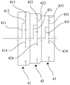
图2为本发明风力发电机组的三级行星齿轮箱的示意图。Fig. 2 is a schematic diagram of a three-stage planetary gearbox of a wind power generating set according to the present invention.
图3为本发明风力发电机组的示意图。Fig. 3 is a schematic diagram of the wind power generating set of the present invention.
图4为本发明单叶片盘车方法的流程图。Fig. 4 is a flow chart of the single blade turning method of the present invention.
附图标记说明:Explanation of reference signs:
差动行星调速齿轮箱 1Differential planetary speed-adjusting
第一输入端 11
第二输入端 12
齿圈 13
调速太阳轮 14Speed governing
行星架 15
行星轮 16
同步发电机 2
避让凹槽 21
调速电机 3
三级行星齿轮箱 4Three-stage planetary gearbox 4
一级行星齿轮组件 41Primary
一级行星架 411
一级行星轮 412Primary
一级齿圈 413
一级太阳轮 414
二级行星齿轮组件 42Secondary
二级行星架 421
二级行星轮 422Secondary
二级齿圈 423
二级太阳轮 424
三级行星齿轮组件 43Three-stage
三级行星架 431Three-
三级行星轮 432Three-stage
三级齿圈 433Three-
三级太阳轮 434Three-
风力发电机组 100
风轮 101
变频器 102
第一变压器 103
电网 104
具体实施方式Detailed ways
下面通过实施例的方式并结合附图来更清楚完整地说明本发明,但并不因此将本发明限制在所述的实施例范围之内。The present invention will be more clearly and completely described below by means of embodiments in conjunction with the accompanying drawings, but the present invention is not limited within the scope of the described embodiments.
如图1-3所示,本实施例提供一种风力发电机组100的传动链,其包括差动行星调速齿轮箱1、同步发电机2和调速电机3,差动行星调速齿轮箱1具有第一输入端11和第二输入端12,第一输入端11用于与风力发电机组100的风轮101连接,第二输入端12用于与调速电机3的输出端连接,差动行星调速齿轮箱1的输出端与同步发电机2的输入端连接,调速电机3和同步发电机2均位于差动行星调速齿轮箱1远离风轮101的一侧。差动行星调速齿轮箱1具有两个输入端,即第一输入端11和第二输入端12,第一输入端11与风轮101连接,通过风轮101将自然环境中的风能转化为机械能,获得初始动力;第二输入端12与调速电机3连接,由于风力是不稳定的,即初始动力是不稳定的,通过调速电机3可以调节差动行星调速齿轮箱1的输出端的转速,并使得该转速恒定,进而使得与差动行星调速齿轮箱1的输出端相连接的同步发电机2的转子的转速恒定,同步发电机2输出的电频率恒定,可以直接或通过第二变压器并入电网104。调速电机3和同步发电机2均位于差动行星调速齿轮箱1远离风轮101的一侧,使得整个传动链的结构更加紧凑,布局更加合理,为适用不同的风轮101直径,可以在传动链与风轮101之间布置不同级数齿轮传动的齿轮箱,提高了传动链的适配性,扩大了传动链的应用范围。As shown in Figures 1-3, this embodiment provides a transmission chain of a wind power generating set 100, which includes a differential planetary speed-regulating
本实施例中,差动行星调速齿轮箱1包括齿圈13和调速太阳轮14,齿圈13的输出轴与同步发电机2连接,调速太阳轮14的输入轴为第二输入端12,调速太阳轮14的输入轴与调速电机3的输出端连接。齿圈13的输出轴为差动行星调速齿轮箱1的输出端,调速太阳轮14的输入轴为差动行星调速齿轮箱1的第二输入端12,调速电机3用于驱动调速太阳轮14转动,进而通过调节行星轮的转动来调节齿圈13的转动,使得齿圈13的转速达到恒定的预设值,使得同步发电机2输出的电频率恒定,可以直接或通过第二变压器并入电网104。In this embodiment, the differential planetary speed-regulating
本实施例中,调速太阳轮14设于齿圈13的内圈,齿圈13的输出轴为空心轴,调速太阳轮14的输入轴穿过齿圈13的输出轴与调速电机3的输出端连接,即齿圈13的输出轴套设于调速太阳轮14的输入轴外侧,使得差动行星调速齿轮箱1的结构更加紧凑,减少空间占用,且方便齿圈13的输出轴连接的同步发电机2和调速太阳轮14的输入轴连接的调速电机3设置于差动行星调速齿轮箱1的同一侧。In this embodiment, the speed-regulating
本实施例中,差动行星调速齿轮箱1还包括行星架15和行星轮16,行星架15的输入轴为第一输入端11,行星架15驱动行星轮16公转,行星轮16位于调速太阳轮14和齿圈13之间并与调速太阳轮14和齿圈13啮合连接。行星架15的输入轴为第一输入端11,方便与风轮101进行直接或间接的连接;行星架15用于驱动行星轮16公转,调速太阳轮14与行星轮16啮合,使得行星轮16在受到来自风轮101的初始动力驱动的同时,还受到来自调速电机3的调节动力的调节,进而使得与其啮合的齿圈13的转速达到恒定的预设值,即使与齿圈13连接的同步发电机2转子的转速达到恒定的预设值,输出的电频率恒定,可以直接或通过第二变压器并入电网104。In this embodiment, the differential planetary speed-regulating
本实施例中,同步发电机2设置于差动行星调速齿轮箱1和调速电机3之间。同步发电机2的输入端与齿圈13的空心输出轴连接,调速太阳轮14的输入轴穿过齿圈13的空心输出轴和同步发电机2后与调速电机3的输入端连接,即差动行星调速齿轮箱1、同步发电机2和调速电机3沿同一轴线、同一方向依次设置,使得结构更加紧凑,布局更加合理,方便传动链在风力发电装置上的安装。In this embodiment, the
本实施例中,同步发电机2的朝向调速电机3一侧具有避让凹槽21,调速电机3部分位于避让凹槽21内,使得调速电机3和同步发电机2之间的距离更小,二者的位置更加紧凑,进一步减少传动链对空间的占用。在是他实施方式中,可以根据实际情况设置避让凹槽21的大小,调速电机3可以全部位于避让凹槽21内。In this embodiment, the side of the
本实施例中,第一输入端11与风轮101间接连接。具体地,传动链还包括基本行星齿轮箱,基本行星齿轮箱布置于风轮101和差动行星调速齿轮箱1之间,基本行星齿轮箱的输入端与风轮101连接,基本行星齿轮箱的输出端与第一输入端11连接。在其他可替代的实施方式中,第一输入端11也可以与风轮101直接连接,即不在风轮101和差动行星调速齿轮箱1之间设置基本行星齿轮箱。In this embodiment, the
基本行星齿轮箱可以将风轮101的转速进行增速并输出给差动行星调速齿轮箱1,例如,在风轮101转速很低的情况下,基本行星齿轮箱可以输入风轮101的较低的转速,然后输出较高的转速给差动行星调速齿轮箱1,以便使得差动行星调速齿轮箱1的第一输入端11的输入转速更接近所需转速,以减少第二输入端12的输入,即减小调速电机3的转速。The basic planetary gearbox can increase the speed of the
本实施例中,基本行星齿轮箱为三级行星齿轮箱4,三级行星齿轮箱4的结构简单,是常用的行星齿轮箱,采用三级行星齿轮箱4有利于增大传动链的应用范围,同时成本较低。In this embodiment, the basic planetary gearbox is a three-stage planetary gearbox 4. The three-stage planetary gearbox 4 has a simple structure and is a commonly used planetary gearbox. The use of a three-stage planetary gearbox 4 is conducive to increasing the application range of the transmission chain , while lower cost.
具体地,如图2所示,三级行星齿轮箱4包括依次连接的一级行星齿轮组件41、二级行星齿轮组件42和三级行星齿轮组件43。一级行星齿轮组件41包括一级行星架411、一级行星轮412、一级齿圈413和一级太阳轮414,一级行星架411的输入轴与风轮101连接,一级行星架411驱动一级行星轮412转动,一级行星轮412驱动一级太阳轮414转动,一级太阳轮414为一级行星齿轮组件41的输出端;二级行星齿轮组件42包括二级行星架421、二级行星轮422、二级齿圈423和二级太阳轮424,二级行星架421与一级太阳轮414连接并驱动二级行星轮422转动,二级行星轮422驱动二级太阳轮424转动,二级太阳轮424为二级行星齿轮组件42的输出端;三级行星齿轮组件43包括三级行星架431、三级行星轮432、三级齿圈433和三级太阳轮434,三级行星架431与二级太阳轮424连接并驱动三级行星轮432转动,三级行星轮432与三级太阳轮434连接,三级太阳轮434与差动行星调速齿轮箱1的行星架15连接。Specifically, as shown in FIG. 2 , the three-stage planetary gearbox 4 includes a first-stage
在其他实施方式中,根据风轮101的转速大小等情况,基本行星齿轮箱也可以采用一级行星齿轮箱或二级行星齿轮箱,并不局限于本实施例。In other embodiments, according to the speed of the
如图3所示,本实施例还提供一种风力发电机组100,包括风轮101,风力发电机组100还包括上述的风力发电机组100的传动链,风轮101与传动链的输入端连接,通过风轮101将自然环境中的风能转化为机械能。传动链中的调速电机3和同步发电机2均位于差动行星调速齿轮箱1远离风轮101的一侧,使得整个风力发电机组100的结构更加紧凑,布局更加合理,为适用不同的风轮101直径,可以在传动链与风轮101之间布置不同级数齿轮传动的齿轮箱,使得风力发电机组100的装配更为方便。As shown in Figure 3, the present embodiment also provides a wind power generating set 100, including a
具体地,在本实施例中,风力发电机组100的同步发电机2为高压发电机并直接连接于电网104。风力发电机组100的差动行星调速齿轮箱1具有两个输入端,即第一输入端11和第二输入端12,第一输入端11与风轮101连接,通过风轮101将自然环境中的风能转化为机械能,获得初始动力;第二输入端12与调速电机3连接,获得调节动力,由于风力是不稳定的,即初始动力是不稳定的,通过调速电机3提供的调节动力可以调节差动行星调速齿轮箱1的输出端的转速,使得该转速恒定,进而使得同步发电机2输出的电频率恒定,可以直接并入电网104。在其他实施方式中,同步发电机2也可以为中压发电机或低压发电机并通过第二变压器连接于电网104。Specifically, in this embodiment, the
本实施例中,风力发电机组100还包括变频器102和第一变压器103,调速电机3、变频器102和第一变压器103依次连接,第一变压器103用于连接电网104。调速电机3通过变频器102和第一变压器103与电网104相连,当风轮101的转速较小,传动链的输出端的转速低于同步发电机2所需的转速时,电网104相当于调速电机3的电源,调速电机3能够为传动链提供动力,使传动链输出端的转速达到同步发电机2所需的转速;当风轮101的转速适中,传动链的输出端的转速刚好达到同步发电机2所需的转速时,调速电机3不做功,提供的动力为零;当传动链的输出端的转速高于同步发电机2所需的转速时,调速电机3此时相当于发电机,能够消耗部分第一输入端11提供的初始动力,降低传动链的输出端的转速至同步发电机2所需的转速,调速电机3发出的电能经变频器102和第一变压器103最终并入电网104。In this embodiment, the wind power generating set 100 further includes a
本实施例中,风力发电机组100还包括制动器,制动器用于停止同步发电机2的转子的转动。可以通过启动制动器来停止同步发电机2的转子的转动,以便进行风力发电机组100的安装或检修,方便快捷。In this embodiment, the wind power generating set 100 further includes a brake, which is used to stop the rotation of the rotor of the
如图4所示,本实施例还提供一种单叶片盘车方法,单叶片盘车方法适用上述的风力发电机组100,其包括以下步骤:As shown in Figure 4, this embodiment also provides a single-blade turning method, which is applicable to the above-mentioned wind power generating set 100, which includes the following steps:
S1、在旋转风轮101的轮毂之前,启动制动器,避免同步发电机2发生运动;S1, before rotating the hub of the
S2、启动调速电机3,通过传动链驱动轮毂转动不同的角度,以分别完成风轮101的各个叶片的安装。S2. Start the
采用单叶片盘车方法对风轮101的叶片进行安装,即对风轮101的叶片逐个进行安装,通过启动制动器来停止同步发电机2转子的转动,此时同步发电机2停止工作,不再进行发电;然后启动调速电机3,电网104为调速电机3的电源,调速电机3驱动差动行星调速齿轮箱1的第一输入端11转动,进而带动风轮101的轮毂转动不同的角度,以分别完成风轮101的各个叶片的安装,此种方法方便快捷,避免了传统方法中需要额外采用盘车装置的缺陷。The blades of the
虽然以上描述了本发明的具体实施方式,但是本领域的技术人员应当理解,这仅是举例说明,本发明的保护范围是由所附权利要求书限定的。本领域的技术人员在不背离本发明的原理和实质的前提下,可以对这些实施方式做出多种变更或修改,但这些变更和修改均落入本发明的保护范围。Although the specific implementation of the present invention has been described above, those skilled in the art should understand that this is only an example, and the protection scope of the present invention is defined by the appended claims. Those skilled in the art can make various changes or modifications to these embodiments without departing from the principle and essence of the present invention, but these changes and modifications all fall within the protection scope of the present invention.
Claims (12)
Priority Applications (1)
| Application Number | Priority Date | Filing Date | Title |
|---|---|---|---|
| CN202210981213.1A CN115355295A (en) | 2022-08-16 | 2022-08-16 | Transmission chain of wind generating set, wind generating set and single-blade barring method |
Applications Claiming Priority (1)
| Application Number | Priority Date | Filing Date | Title |
|---|---|---|---|
| CN202210981213.1A CN115355295A (en) | 2022-08-16 | 2022-08-16 | Transmission chain of wind generating set, wind generating set and single-blade barring method |
Publications (1)
| Publication Number | Publication Date |
|---|---|
| CN115355295A true CN115355295A (en) | 2022-11-18 |
Family
ID=84033067
Family Applications (1)
| Application Number | Title | Priority Date | Filing Date |
|---|---|---|---|
| CN202210981213.1A Pending CN115355295A (en) | 2022-08-16 | 2022-08-16 | Transmission chain of wind generating set, wind generating set and single-blade barring method |
Country Status (1)
| Country | Link |
|---|---|
| CN (1) | CN115355295A (en) |
Cited By (2)
| Publication number | Priority date | Publication date | Assignee | Title |
|---|---|---|---|---|
| CN116201697A (en) * | 2023-02-23 | 2023-06-02 | 上海电气风电集团股份有限公司 | Wind turbine transmission chain and topology |
| CN116335889A (en) * | 2023-02-23 | 2023-06-27 | 上海电气风电集团股份有限公司 | Drive chain of wind power generating set and wind power generating set including same |
Citations (21)
| Publication number | Priority date | Publication date | Assignee | Title |
|---|---|---|---|---|
| AT508051A1 (en) * | 2009-03-26 | 2010-10-15 | Hehenberger Gerald Dipl Ing | ENERGY EQUIPMENT, IN PARTICULAR WIND POWER PLANT |
| CN201621013U (en) * | 2010-02-05 | 2010-11-03 | 国电联合动力技术有限公司 | A speed-adjustable wind turbine |
| CN102146892A (en) * | 2011-02-17 | 2011-08-10 | 国电联合动力技术有限公司 | Variable-speed ratio wind power speed increasing box |
| US20110234179A1 (en) * | 2008-10-09 | 2011-09-29 | Gerald Hehenberger | Differential for a wind power station |
| CN202001208U (en) * | 2011-02-17 | 2011-10-05 | 国电联合动力技术有限公司 | Variable-speed ratio wind power speed increasing box |
| CN102338035A (en) * | 2011-08-30 | 2012-02-01 | 哈尔滨工业大学 | Composite rotor structure variable-speed constant-frequency wind power generator system and control method thereof |
| CN202215429U (en) * | 2011-08-31 | 2012-05-09 | 国电联合动力技术有限公司 | Control system of differential gear box speed regulation type synchronous wind generating set |
| CN102852726A (en) * | 2012-08-29 | 2013-01-02 | 华北电力大学 | Gird-connected wind power generation system with self-adaptive speed regulation composite transmission based on differential mechanism |
| CN202718814U (en) * | 2012-07-04 | 2013-02-06 | 沈阳华创风能有限公司 | Direct grid wind turbine generating set of synchronous generator |
| CN202732233U (en) * | 2012-09-04 | 2013-02-13 | 沈阳华创风能有限公司 | Variable-ratio wind generating set |
| WO2013023228A1 (en) * | 2011-08-18 | 2013-02-21 | Gerald Hehenberger | Energy-generating installation, particularly a wind turbine |
| CN202768296U (en) * | 2012-08-29 | 2013-03-06 | 华北电力大学 | Self-adaption speed regulating mechanism for transmission of grid-tied wind driven generator set |
| DE102012205248A1 (en) * | 2012-03-30 | 2013-10-02 | Suzlon Energy Gmbh | Drive train for wind turbine, has gear box constructed from combination of planetary- and spur gear stages such that gear box exhibits preset transmission ratio, and generator formed as high frequency generator with preset working area |
| US8668610B1 (en) * | 2012-10-19 | 2014-03-11 | Jinan Railway Vehicles Equipment Co., Ltd. | Electro-hydraulic servo synchronizer for MW wind turbine generator system |
| JP5550781B2 (en) * | 2011-09-22 | 2014-07-16 | 三菱重工業株式会社 | Renewable energy power generator and method of operating the renewable energy power generator |
| US20140203561A1 (en) * | 2013-01-23 | 2014-07-24 | General Electric Company | Variable input synchronous output drivetrain for wind turbine |
| US20150115614A1 (en) * | 2013-10-30 | 2015-04-30 | Airgenesis, LLC | Motor Assisted Power Generation System |
| CN106837703A (en) * | 2017-04-13 | 2017-06-13 | 泗阳高传电机制造有限公司 | Half-direct-drive wind driven generator |
| CN111669061A (en) * | 2020-05-20 | 2020-09-15 | 浙江大学 | Anti-towing systems and wind turbines |
| CN213323635U (en) * | 2020-09-29 | 2021-06-01 | 扬州永诚钢结构有限公司 | A high-efficiency and energy-saving hybrid power system for ships |
| CN112943555A (en) * | 2021-02-20 | 2021-06-11 | 上海电气风电集团股份有限公司 | Shafting structure for wind generating set and wind generating set |
-
2022
- 2022-08-16 CN CN202210981213.1A patent/CN115355295A/en active Pending
Patent Citations (21)
| Publication number | Priority date | Publication date | Assignee | Title |
|---|---|---|---|---|
| US20110234179A1 (en) * | 2008-10-09 | 2011-09-29 | Gerald Hehenberger | Differential for a wind power station |
| AT508051A1 (en) * | 2009-03-26 | 2010-10-15 | Hehenberger Gerald Dipl Ing | ENERGY EQUIPMENT, IN PARTICULAR WIND POWER PLANT |
| CN201621013U (en) * | 2010-02-05 | 2010-11-03 | 国电联合动力技术有限公司 | A speed-adjustable wind turbine |
| CN102146892A (en) * | 2011-02-17 | 2011-08-10 | 国电联合动力技术有限公司 | Variable-speed ratio wind power speed increasing box |
| CN202001208U (en) * | 2011-02-17 | 2011-10-05 | 国电联合动力技术有限公司 | Variable-speed ratio wind power speed increasing box |
| WO2013023228A1 (en) * | 2011-08-18 | 2013-02-21 | Gerald Hehenberger | Energy-generating installation, particularly a wind turbine |
| CN102338035A (en) * | 2011-08-30 | 2012-02-01 | 哈尔滨工业大学 | Composite rotor structure variable-speed constant-frequency wind power generator system and control method thereof |
| CN202215429U (en) * | 2011-08-31 | 2012-05-09 | 国电联合动力技术有限公司 | Control system of differential gear box speed regulation type synchronous wind generating set |
| JP5550781B2 (en) * | 2011-09-22 | 2014-07-16 | 三菱重工業株式会社 | Renewable energy power generator and method of operating the renewable energy power generator |
| DE102012205248A1 (en) * | 2012-03-30 | 2013-10-02 | Suzlon Energy Gmbh | Drive train for wind turbine, has gear box constructed from combination of planetary- and spur gear stages such that gear box exhibits preset transmission ratio, and generator formed as high frequency generator with preset working area |
| CN202718814U (en) * | 2012-07-04 | 2013-02-06 | 沈阳华创风能有限公司 | Direct grid wind turbine generating set of synchronous generator |
| CN202768296U (en) * | 2012-08-29 | 2013-03-06 | 华北电力大学 | Self-adaption speed regulating mechanism for transmission of grid-tied wind driven generator set |
| CN102852726A (en) * | 2012-08-29 | 2013-01-02 | 华北电力大学 | Gird-connected wind power generation system with self-adaptive speed regulation composite transmission based on differential mechanism |
| CN202732233U (en) * | 2012-09-04 | 2013-02-13 | 沈阳华创风能有限公司 | Variable-ratio wind generating set |
| US8668610B1 (en) * | 2012-10-19 | 2014-03-11 | Jinan Railway Vehicles Equipment Co., Ltd. | Electro-hydraulic servo synchronizer for MW wind turbine generator system |
| US20140203561A1 (en) * | 2013-01-23 | 2014-07-24 | General Electric Company | Variable input synchronous output drivetrain for wind turbine |
| US20150115614A1 (en) * | 2013-10-30 | 2015-04-30 | Airgenesis, LLC | Motor Assisted Power Generation System |
| CN106837703A (en) * | 2017-04-13 | 2017-06-13 | 泗阳高传电机制造有限公司 | Half-direct-drive wind driven generator |
| CN111669061A (en) * | 2020-05-20 | 2020-09-15 | 浙江大学 | Anti-towing systems and wind turbines |
| CN213323635U (en) * | 2020-09-29 | 2021-06-01 | 扬州永诚钢结构有限公司 | A high-efficiency and energy-saving hybrid power system for ships |
| CN112943555A (en) * | 2021-02-20 | 2021-06-11 | 上海电气风电集团股份有限公司 | Shafting structure for wind generating set and wind generating set |
Cited By (2)
| Publication number | Priority date | Publication date | Assignee | Title |
|---|---|---|---|---|
| CN116201697A (en) * | 2023-02-23 | 2023-06-02 | 上海电气风电集团股份有限公司 | Wind turbine transmission chain and topology |
| CN116335889A (en) * | 2023-02-23 | 2023-06-27 | 上海电气风电集团股份有限公司 | Drive chain of wind power generating set and wind power generating set including same |
Similar Documents
| Publication | Publication Date | Title |
|---|---|---|
| CN102483043A (en) | Wind power plant and method for controlling the operation of a wind power plant | |
| CN106949018B (en) | A kind of compound main transmission of wind energy conversion system mechanical electromagnetic | |
| CN101598113A (en) | A kind of wind power generation device | |
| CN101344073A (en) | Variable speed and constant frequency device for wind power generating set | |
| US8845471B2 (en) | Variable input synchronous output drivetrain for wind turbine | |
| CN102365457A (en) | Energy harvesting equipment, especially wind power plants | |
| CN106150916A (en) | A kind of bilobed wheel synchro wind generator group | |
| CN101649810B (en) | Wind power generation variable pitch speed reducer | |
| CN102269123B (en) | Wind power generation device | |
| CN102365456A (en) | Energy harvesting equipment, especially wind power plants | |
| CN102324801B (en) | wind power plant | |
| CN103986278A (en) | Different connection motor | |
| CN202001208U (en) | Variable-speed ratio wind power speed increasing box | |
| CN202732233U (en) | Variable-ratio wind generating set | |
| KR101028960B1 (en) | Wind Turbine Facility | |
| CN115467789A (en) | A wind source simulation experiment equipment and control method for comprehensive energy in the park | |
| CN114576089A (en) | High-efficiency power generation method of vertical axis turbine wind generating set at low wind speed | |
| GB2483866A (en) | Electric generator apparatus for a fluid turbine arrangement | |
| CN116201697A (en) | Wind turbine transmission chain and topology | |
| CN102013762A (en) | Variable speed constant frequency device of wind turbine generator set | |
| CN206246284U (en) | A kind of bilobed wheel synchro wind generator group | |
| CN202187862U (en) | Speed regulating control device used for front end speed regulating type wind generator system | |
| CN108708832A (en) | Wind-power electricity generation stepless speed-regulating device | |
| CN115289194A (en) | Transmission chain, wind generating set and power generation method thereof | |
| CN202718814U (en) | Direct grid wind turbine generating set of synchronous generator |
Legal Events
| Date | Code | Title | Description |
|---|---|---|---|
| PB01 | Publication | ||
| PB01 | Publication | ||
| SE01 | Entry into force of request for substantive examination | ||
| SE01 | Entry into force of request for substantive examination | ||
| RJ01 | Rejection of invention patent application after publication | ||
| RJ01 | Rejection of invention patent application after publication |
Application publication date: 20221118 |