CN115342623A - Quick automatic drying equipment of textile fabric - Google Patents
Quick automatic drying equipment of textile fabric Download PDFInfo
- Publication number
- CN115342623A CN115342623A CN202210988507.7A CN202210988507A CN115342623A CN 115342623 A CN115342623 A CN 115342623A CN 202210988507 A CN202210988507 A CN 202210988507A CN 115342623 A CN115342623 A CN 115342623A
- Authority
- CN
- China
- Prior art keywords
- roller
- fabric
- box
- drying
- flattening
- Prior art date
- Legal status (The legal status is an assumption and is not a legal conclusion. Google has not performed a legal analysis and makes no representation as to the accuracy of the status listed.)
- Granted
Links
Images


Classifications
-
- F—MECHANICAL ENGINEERING; LIGHTING; HEATING; WEAPONS; BLASTING
- F26—DRYING
- F26B—DRYING SOLID MATERIALS OR OBJECTS BY REMOVING LIQUID THEREFROM
- F26B13/00—Machines and apparatus for drying fabrics, fibres, yarns, or other materials in long lengths, with progressive movement
- F26B13/24—Arrangements of devices using drying processes not involving heating
- F26B13/28—Arrangements of devices using drying processes not involving heating for applying pressure; for brushing; for wiping
-
- D—TEXTILES; PAPER
- D06—TREATMENT OF TEXTILES OR THE LIKE; LAUNDERING; FLEXIBLE MATERIALS NOT OTHERWISE PROVIDED FOR
- D06C—FINISHING, DRESSING, TENTERING OR STRETCHING TEXTILE FABRICS
- D06C15/00—Calendering, pressing, ironing, glossing or glazing textile fabrics
- D06C15/02—Calendering, pressing, ironing, glossing or glazing textile fabrics between co-operating press or calender rolls
-
- F—MECHANICAL ENGINEERING; LIGHTING; HEATING; WEAPONS; BLASTING
- F26—DRYING
- F26B—DRYING SOLID MATERIALS OR OBJECTS BY REMOVING LIQUID THEREFROM
- F26B13/00—Machines and apparatus for drying fabrics, fibres, yarns, or other materials in long lengths, with progressive movement
- F26B13/10—Arrangements for feeding, heating or supporting materials; Controlling movement, tension or position of materials
- F26B13/14—Rollers, drums, cylinders; Arrangement of drives, supports, bearings, cleaning
-
- F—MECHANICAL ENGINEERING; LIGHTING; HEATING; WEAPONS; BLASTING
- F26—DRYING
- F26B—DRYING SOLID MATERIALS OR OBJECTS BY REMOVING LIQUID THEREFROM
- F26B21/00—Arrangements for supplying or controlling air or other gases for drying solid materials or objects
- F26B21/50—Ducting arrangements from the source of air or other gases to the materials or objects being dried
-
- F—MECHANICAL ENGINEERING; LIGHTING; HEATING; WEAPONS; BLASTING
- F26—DRYING
- F26B—DRYING SOLID MATERIALS OR OBJECTS BY REMOVING LIQUID THEREFROM
- F26B25/00—Details of general application not covered by group F26B21/00 or F26B23/00
-
- F—MECHANICAL ENGINEERING; LIGHTING; HEATING; WEAPONS; BLASTING
- F26—DRYING
- F26B—DRYING SOLID MATERIALS OR OBJECTS BY REMOVING LIQUID THEREFROM
- F26B25/00—Details of general application not covered by group F26B21/00 or F26B23/00
- F26B25/001—Handling, e.g. loading or unloading arrangements
- F26B25/003—Handling, e.g. loading or unloading arrangements for articles
-
- F—MECHANICAL ENGINEERING; LIGHTING; HEATING; WEAPONS; BLASTING
- F26—DRYING
- F26B—DRYING SOLID MATERIALS OR OBJECTS BY REMOVING LIQUID THEREFROM
- F26B25/00—Details of general application not covered by group F26B21/00 or F26B23/00
- F26B25/20—Rollers
Landscapes
- Engineering & Computer Science (AREA)
- Mechanical Engineering (AREA)
- General Engineering & Computer Science (AREA)
- Textile Engineering (AREA)
- Treatment Of Fiber Materials (AREA)
Abstract
本发明公开了一种纺织面料快速自动烘干设备,涉及纺织面料加工技术领域,包括收集辊、传送箱和烘干箱,所述烘干箱的一侧设置有传送箱,烘干箱的另一侧设置有收集辊,通过转动装置将上铺平辊放下,使其与压在面料顶面,通过上铺平电机的输出端驱动上铺平辊转动,将朝上褶皱的面料铺平,同时通过转动装置将上压辊倾斜槽内的下铺平辊上,对面料施加压力,使得面料与下铺平辊接触,通过下铺平电机的输出端驱动下铺平辊转动,实现面料朝下褶皱的铺平工作;可实现面料朝上褶皱或者朝下褶皱的铺平工作,不需要人工一一平整,避免烘干后褶皱痕迹明显,保证燃料染色定色均匀,影响面料美观及后续加工。
The invention discloses a fast automatic drying equipment for textile fabrics, which relates to the technical field of textile fabric processing, and comprises a collection roller, a transmission box and a drying box, one side of the drying box is provided with a transmission box, and the other side of the drying box is There is a collection roller on one side, and the upper flattening roller is lowered by the rotating device to make it press against the top surface of the fabric, and the upper flattening roller is driven to rotate by the output end of the upper flattening motor, so that the upwardly folded fabric is flattened. At the same time, through the rotating device, the lower flat roller in the inclined groove of the upper pressure roller is put on the fabric, so that the fabric is in contact with the lower flat roller, and the output end of the lower flat motor drives the lower flat roller to rotate, so that the fabric is facing Flattening of lower folds; it can realize the flattening of upward or downward folds of the fabric, without manual leveling, avoiding obvious wrinkles after drying, ensuring uniform dyeing and color fixing of fuel, affecting the appearance of fabrics and subsequent processing .
Description
技术领域technical field
本发明涉及纺织面料加工技术领域,尤其涉及一种纺织面料快速自动烘干设备。The invention relates to the technical field of textile fabric processing, in particular to a rapid automatic drying equipment for textile fabrics.
背景技术Background technique
纺织面料在进行加工后,会有染色烘干步骤,目前纺织面料上料时需要人工将面料的边和角均放置到治具底部,以保证面料进行烘干时不出褶皱,而产生的折痕导致染色定色不均,影响美观;After the textile fabric is processed, there will be a dyeing and drying step. At present, when the textile fabric is loaded, it is necessary to manually place the edges and corners of the fabric on the bottom of the jig to ensure that the fabric does not have wrinkles when it is dried. Marks lead to uneven dyeing and color fixation, which affects the appearance;
需要将面料平放到传送台上时,通过上转动电机的输出端驱动转动板转动,使得转动板在两个安装板转动,实现上压辊或上铺平辊的翘起,便于面料的初始放置工作,不需要一一将面料塞入上压辊或上铺平辊下方,提高上料效率;且面料在传送过程中,容易出现朝下或者朝上的褶皱,需要人工一一平整,操作繁杂;经过热烘轴烘干后纺织面料会出现膨胀,直接卷绕收集会占用较大空间,不便于后续的收集辊收集。When the fabric needs to be placed flat on the transfer table, the output end of the upper rotation motor is used to drive the rotating plate to rotate, so that the rotating plate rotates on the two mounting plates to realize the tilting of the upper pressing roller or the upper laying roller, which is convenient for the initial production of the fabric. For placing work, it is not necessary to stuff the fabrics one by one under the upper pressing roller or the upper flattening roller to improve the feeding efficiency; and the fabrics are prone to downward or upward wrinkles during the transmission process, which requires manual leveling and operation. Complicated; the textile fabric will swell after being dried by the hot drying shaft, and the direct winding collection will take up a large space, which is not convenient for the subsequent collection roller collection.
发明内容Contents of the invention
本发明的目的是为了解决现有技术中存在的问题,而提出的一种纺织面料快速自动烘干设备。The object of the present invention is to solve the problems existing in the prior art, and propose a kind of fast automatic drying equipment for textile fabrics.
为达到上述目的,本发明采用了下列技术方案:To achieve the above object, the present invention adopts the following technical solutions:
一种纺织面料快速自动烘干设备,包括收集辊、传送箱和烘干箱,所述烘干箱的一侧设置有传送箱,烘干箱的另一侧设置有收集辊,传送箱的顶面设置有传送台,传送台的底部两端设置有传送辊,每个传送辊上方的传送台上均开设有用于传送辊顶端穿过矩形槽,所述传送箱的顶部两侧对称设置有若干用于铺平面料朝上褶皱的上铺平装置,所述传送箱的内部对称设置有若干用于铺平面料朝下褶皱的下铺平装置;所述烘干箱的内部靠近传送箱的一侧安装有初步滤水装置,初步滤水装置的一侧设置有支撑轴,支撑轴的一侧设置有调节轴,调节轴与支撑轴之间设置有两个热烘轴,烘干箱的顶部设置有气泵,气泵的下方位于烘干箱内设置有集气管,集气管的底部连通设置有若干用于对面料吹风的喷气孔。A rapid and automatic drying equipment for textile fabrics, comprising a collecting roller, a transfer box and a drying box, one side of the drying box is provided with a transfer box, the other side of the drying box is provided with a collecting roller, and the top of the transfer box is There is a conveying table on the surface, and the two ends of the bottom of the conveying table are provided with conveying rollers. The conveying stage above each conveying roller is provided with a rectangular groove for the top of the conveying roller to pass through. There are several symmetrically arranged on both sides of the top of the conveying box. For the upper flattening device for laying the flat material upward folds, the interior of the transfer box is symmetrically provided with several lower flattening devices for the downward folds of the flat fabric; the inside of the drying box is close to one of the transfer box A preliminary water filtering device is installed on the side, and one side of the preliminary water filtering device is provided with a supporting shaft, and one side of the supporting shaft is provided with an adjusting shaft, and two heat drying shafts are arranged between the adjusting shaft and the supporting shaft, and the top of the drying box An air pump is provided, and an air collecting pipe is arranged under the air pump in the drying box, and the bottom of the air collecting pipe is communicated with a plurality of air jet holes for blowing the fabric.
作为本发明的进一步技术方案,所述上铺平装置装置包括转动装置以及倾斜设置的上铺平辊,转动装置的一侧设置有驱动上铺平辊转动的上铺平电机,需要将面料平放到传送台上时,通过转动装置驱动上铺平辊转动翘起,面料放置完成后,再通过转动装置将上铺平辊放下,使其与压在面料顶面,通过上铺平电机的输出端驱动上铺平辊转动,将朝上褶皱的面料铺平。As a further technical solution of the present invention, the upper flattening device includes a rotating device and an upper flattening roller arranged obliquely. One side of the rotating device is provided with an upper flattening motor that drives the upper flattening roller to rotate. When it is placed on the conveying table, the upper paving roller is driven to rotate and tilt by the rotating device. After the fabric is placed, the upper paving roller is put down by the rotating device so that it is pressed against the top surface of the fabric and passed by the upper paving motor. The output end drives the upper paving roller to rotate, and paves the upwardly folded fabric.
作为本发明的进一步技术方案,所述下铺平装置包括固定设置在传送箱上的下固定板,下固定板的一侧固定有下铺平电机,下铺平电机的输出端贯穿下固定板且固定连接有下铺平辊,位于下铺平辊正上方的传送台上开设有倾斜槽,下铺平辊的顶面穿过倾斜槽,使得下铺平辊的顶面能够穿过传送台与面料底面接触,实现下铺平工作。As a further technical solution of the present invention, the lower paving device includes a lower fixed plate fixedly arranged on the transfer box, a lower paved motor is fixed on one side of the lower fixed plate, and the output end of the lower paved motor passes through the lower fixed plate And the lower laying roller is fixedly connected, and the conveying table located directly above the lower laying roller is provided with an inclined groove, and the top surface of the lower laying roller passes through the inclined groove, so that the top surface of the lower laying roller can pass through the conveying platform Contact with the bottom surface of the fabric to realize the lower laying work.
作为本发明的进一步技术方案,位于下铺平装置上方的传送箱顶部设置有转动装置以及倾斜设置的上压辊,上压辊转动设置在转动装置的一侧,上压辊与倾斜槽的位置对应,放置好面料后,通过转动装置将上压辊倾斜槽内的下铺平辊上,对面料施加压力,使得面料与下铺平辊接触,通过下铺平电机的输出端驱动下铺平辊转动,实现面料朝下褶皱的铺平工作。As a further technical solution of the present invention, the top of the transfer box above the lower paving device is provided with a rotating device and an upper pressing roller arranged obliquely, and the upper pressing roller is rotated and arranged on one side of the rotating device. Correspondingly, after the fabric is placed, use the rotating device to place the lower flat roller in the inclined groove of the upper pressure roller on the fabric, so that the fabric is in contact with the lower flat roller, and is driven by the output end of the lower flat motor to pave The rollers rotate to achieve the laying down of the folds of the fabric facing downwards.
作为本发明的进一步技术方案,所述转动装置包括固定设置在传送箱顶部的两个安装板,两个安装板之间转动设置有转动板,上压辊与上铺平辊均设置在转动板上,其中一个安装板的一侧固定有驱动转动板转动的上转动电机,通过上转动电机的输出端驱动转动板转动,使得转动板在两个安装板转动,实现上压辊或上铺平辊的翘起与下方,便于面料的初始放置工作,不需要一一将面料塞入上压辊或上铺平辊下方,提高上料效率。As a further technical solution of the present invention, the rotating device includes two mounting plates fixedly arranged on the top of the conveying box, a rotating plate is arranged between the two mounting plates, and the upper pressing roller and the upper flattening roller are both arranged on the rotating plate One side of one of the mounting plates is fixed with an upper rotating motor that drives the rotating plate to rotate, and the output end of the upper rotating motor drives the rotating plate to rotate, so that the rotating plate rotates on the two mounting plates to realize the upper pressing roller or upper paving The tilting and lowering of the rollers are convenient for the initial placement of the fabrics, and it is not necessary to stuff the fabrics under the upper pressing roller or the upper flat roller one by one, so as to improve the feeding efficiency.
作为本发明的进一步技术方案,所述初步滤水装置包括转动设置在烘干箱内部的初步滤水辊,初步滤水辊的下方固定安装有固定轴,固定轴上通过扭簧连接有加压板,加压板的下方设置有接水箱,通过扭簧的扭力,使得加压板压在初步滤水辊的表面,潮湿的面料经过加压板与初步滤水辊之间,受到加压力,使得水分沿着加压板流入到接水箱中,实现面料初步滤水工作。As a further technical solution of the present invention, the preliminary water filtering device includes a preliminary water filtering roller rotatably arranged inside the drying box, a fixed shaft is fixedly installed under the preliminary water filtering roller, and a pressurizing shaft is connected to the fixed shaft through a torsion spring. The bottom of the pressure plate is provided with a water receiving box. Through the torsion of the torsion spring, the pressure plate is pressed on the surface of the preliminary water filter roller, and the wet fabric passes between the pressure plate and the preliminary water filter roller and is subjected to pressure. Make the water flow into the water receiving tank along the pressure plate, and realize the preliminary water filtering work of the fabric.
作为本发明的进一步技术方案,所述烘干箱的底部设置有若干排气孔,烘干箱与收集辊之间设置有压平装置。As a further technical solution of the present invention, several exhaust holes are provided at the bottom of the drying box, and a flattening device is provided between the drying box and the collecting roller.
作为本发明的进一步技术方案,所述压平装置包括两个平行设置的侧板,两个侧板之间的底部位置转动设置有承接辊,承接辊的上方设置有加压辊,每个侧板的中部均开设有滑槽,滑槽的内部滑动有滑块,加压辊的两端分别与两个滑块转动连接,滑槽的内部竖直方向转动设置有丝杆,丝杆螺纹贯穿滑块,每个侧板的顶部均设置有驱动丝杆转动压平电机,烘干后的面料穿过加压辊与承接辊之间,通过压平电机同步驱动丝杆转动,使得滑块向下移动,继而使得加压辊向下移动,通过与承接辊配合,实现面料压平工作,便于后续的收集辊收集。As a further technical solution of the present invention, the flattening device includes two side plates arranged in parallel, a receiving roller is installed at the bottom position between the two side plates, and a pressure roller is arranged above the receiving roller. The middle part of the plate is provided with a chute, the inside of the chute slides with a slider, the two ends of the pressure roller are respectively connected to the two sliders in rotation, the inside of the chute rotates vertically with a screw, and the thread of the screw runs through Slider, the top of each side plate is equipped with a driving screw to rotate and flatten the motor. The dried fabric passes between the pressure roller and the receiving roller, and the screw is driven synchronously by the flattening motor to rotate, so that the slider moves toward the Move down, and then make the pressure roller move down, and cooperate with the receiving roller to realize the flattening of the fabric, which is convenient for the subsequent collection of the collection roller.
本发明的有益效果:Beneficial effects of the present invention:
1、本发明需要将面料平放到传送台上时,通过上转动电机的输出端驱动转动板转动,使得转动板在两个安装板转动,实现上压辊或上铺平辊的翘起,便于面料的初始放置工作,不需要一一将面料塞入上压辊或上铺平辊下方,提高上料效率;1. In the present invention, when the fabric is placed flat on the conveying table, the output end of the upper rotating motor drives the rotating plate to rotate, so that the rotating plate rotates on the two mounting plates to realize the tilting of the upper pressing roller or the upper flat roller. It is convenient for the initial placement of fabrics, and it is not necessary to stuff the fabrics one by one under the upper pressing roller or the upper flat roller, so as to improve the feeding efficiency;
2、本发明面料放置完成后,通过转动装置将上铺平辊放下,使其与压在面料顶面,通过上铺平电机的输出端驱动上铺平辊转动,将朝上褶皱的面料铺平,同时通过转动装置将上压辊倾斜槽内的下铺平辊上,对面料施加压力,使得面料与下铺平辊接触,通过下铺平电机的输出端驱动下铺平辊转动,实现面料朝下褶皱的铺平工作;可实现面料朝上褶皱或者朝下褶皱的铺平工作,不需要人工一一平整,避免烘干后褶皱痕迹明显,保证燃料染色定色均匀,影响面料美观及后续加工;2. After the fabric of the present invention is placed, the upper laying roller is lowered by the rotating device, and pressed against the top surface of the fabric, and the upper laying roller is driven to rotate by the output end of the upper laying motor, and the upwardly folded fabric is laid At the same time, through the rotating device, the lower flat roller in the inclined groove of the upper pressure roller is applied to the fabric, so that the fabric is in contact with the lower flat roller, and the lower flat roller is driven to rotate through the output end of the lower flat motor to achieve The paving work of fabric facing down folds; it can realize the paving work of facing up or down folds of fabrics, without manual leveling one by one, avoiding obvious wrinkles after drying, ensuring uniform dyeing and color fixing of fuel, affecting the appearance and quality of fabrics Subsequent processing;
3、本发明中,潮湿的面料经过加压板与初步滤水辊之间,受到加压力,使得水分沿着加压板流入到接水箱中,实现面料初步滤水工作,面料通过两个热烘轴时,热烘轴会对面料进行热烘,配合喷气孔喷出的气流,快速烘干面料;烘干后的面料穿过加压辊与承接辊之间,通过压平电机同步驱动丝杆转动,使得滑块向下移动,继而使得加压辊向下移动,通过与承接辊配合,实现面料压平工作,便于后续的收集辊收集。3. In the present invention, the wet fabric passes between the pressure plate and the preliminary water filter roller, and is pressurized so that the water flows into the water receiving tank along the pressure plate to realize the preliminary water filtration work of the fabric. The fabric passes through two hot When drying the shaft, the heating shaft will heat the fabric, and cooperate with the airflow from the air jet hole to quickly dry the fabric; the dried fabric passes between the pressure roller and the receiving roller, and the wire is synchronously driven by the flattening motor. The rotation of the rod makes the slider move down, and then the pressure roller moves down, and cooperates with the receiving roller to realize the flattening of the fabric, which is convenient for subsequent collection by the collecting roller.
附图说明Description of drawings
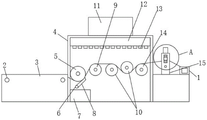
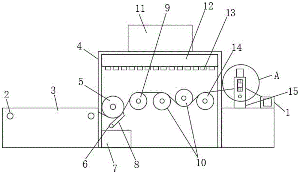
图1为本发明的整体结构示意图;Fig. 1 is the overall structure schematic diagram of the present invention;
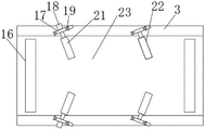
图2为本发明传送箱的俯视图;Fig. 2 is the top view of the transfer box of the present invention;
图3为本发明传送箱的内部结构示意图;Fig. 3 is a schematic diagram of the internal structure of the transfer box of the present invention;
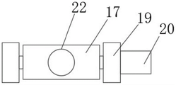
图4为本发明转动装置的结构示意图;Fig. 4 is the structural representation of rotating device of the present invention;
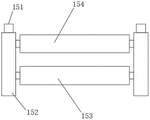
图5为本发明压平装置的结构示意图;Fig. 5 is the structural representation of flattening device of the present invention;
图6为本发明图1中A区域的放大结构示意图。FIG. 6 is a schematic diagram of an enlarged structure of area A in FIG. 1 of the present invention.
图中:1、收集辊;2、传送辊;3、传送箱;4、烘干箱;5、初步滤水辊;6、固定轴;7、接水箱;8、加压板;9、支撑轴;10、热烘轴;11、气泵;12、集气管;13、喷气孔;14、调节轴;15、压平装置;151、压平电机;152、侧板;153、承接辊;154、加压辊;155、丝杆;156、滑槽;157、滑块;16、矩形槽;17、转动板;18、上铺平电机;19、安装板;20、上转动电机;21、上铺平辊;22、上压辊;23、传送台;24、下铺平辊;25、下固定板;26、下转动电机。In the figure: 1. Collecting roller; 2. Conveying roller; 3. Conveying box; 4. Drying box; 5. Preliminary water filter roller; 6. Fixed shaft; 7. Water receiving tank; 8. Pressure plate; 9. Support Shaft; 10, heat drying shaft; 11, air pump; 12, air collecting pipe; 13, jet hole; 14, adjustment shaft; 15, flattening device; 151, flattening motor; 152, side plate; 153, receiving roller; 154 155, screw mandrel; 156, chute; 157, slide block; 16, rectangular groove; 17, rotating plate; 18, upper paving motor; 19, mounting plate; 20, upper rotating motor; 21, 22, the upper pressure roller; 23, the transmission platform; 24, the lower flat roller; 25, the lower fixing plate; 26, the lower rotating motor.
具体实施方式Detailed ways
为更进一步阐述本发明为实现预定目的所采取的技术手段及功效,以下结合附图及较佳实施例,对依据本发明的具体实施方式、结构、特征及其功效,详细说明如后。In order to further explain the technical means and effects adopted by the present invention to achieve the intended purpose, the specific implementation, structure, features and effects of the present invention will be described in detail below in conjunction with the accompanying drawings and preferred embodiments.
参照图1-图6,一种纺织面料快速自动烘干设备,包括收集辊1、传送箱3和烘干箱4,所述烘干箱4的一侧设置有传送箱3,烘干箱4的另一侧设置有收集辊1,传送箱3的顶面设置有传送台23,传送台23的底部两端设置有传送辊2,每个传送辊2上方的传送台23上均开设有用于传送辊2顶端穿过矩形槽16,所述传送箱3的顶部两侧对称设置有若干用于铺平面料朝上褶皱的上铺平装置,所述传送箱3的内部对称设置有若干用于铺平面料朝下褶皱的下铺平装置;所述烘干箱4的内部靠近传送箱3的一侧安装有初步滤水装置,初步滤水装置的一侧设置有支撑轴9,支撑轴9的一侧设置有调节轴14,调节轴14与支撑轴9之间设置有两个热烘轴10,烘干箱4的顶部设置有气泵11,气泵11的下方位于烘干箱4内设置有集气管12,集气管12的底部连通设置有若干用于对面料吹风的喷气孔13。所述上铺平装置装置包括转动装置以及倾斜设置的上铺平辊21,转动装置的一侧设置有驱动上铺平辊21转动的上铺平电机18,需要将面料平放到传送台23上时,通过转动装置驱动上铺平辊21转动翘起,面料放置完成后,再通过转动装置将上铺平辊21放下,使其与压在面料顶面,通过上铺平电机18的输出端驱动上铺平辊21转动,将朝上褶皱的面料铺平。所述下铺平装置包括固定设置在传送箱3上的下固定板25,下固定板25的一侧固定有下铺平电机26,下铺平电机26的输出端贯穿下固定板25且固定连接有下铺平辊24,位于下铺平辊24正上方的传送台23上开设有倾斜槽,下铺平辊24的顶面穿过倾斜槽,使得下铺平辊24的顶面能够穿过传送台23与面料底面接触,实现下铺平工作。位于下铺平装置上方的传送箱3顶部设置有转动装置以及倾斜设置的上压辊22,上压辊22转动设置在转动装置的一侧,上压辊22与倾斜槽的位置对应,放置好面料后,通过转动装置将上压辊22倾斜槽内的下铺平辊24上,对面料施加压力,使得面料与下铺平辊24接触,通过下铺平电机26的输出端驱动下铺平辊24转动,实现面料朝下褶皱的铺平工作。Referring to Fig. 1-Fig. 6, a kind of rapid automatic drying equipment for textile fabrics comprises a
所述转动装置包括固定设置在传送箱3顶部的两个安装板19,两个安装板19之间转动设置有转动板17,上压辊22与上铺平辊21均设置在转动板17上,其中一个安装板19的一侧固定有驱动转动板17转动的上转动电机20,通过上转动电机20的输出端驱动转动板17转动,使得转动板17在两个安装板19转动,实现上压辊22或上铺平辊21的翘起与下方,便于面料的初始放置工作,不需要一一将面料塞入上压辊22或上铺平辊21下方,提高上料效率。The rotating device includes two mounting
所述初步滤水装置包括转动设置在烘干箱4内部的初步滤水辊5,初步滤水辊5的下方固定安装有固定轴6,固定轴6上通过扭簧连接有加压板8,加压板8的下方设置有接水箱7,通过扭簧的扭力,使得加压板8压在初步滤水辊5的表面,潮湿的面料经过加压板8与初步滤水辊5之间,受到加压力,使得水分沿着加压板8流入到接水箱7中,实现面料初步滤水工作。The preliminary water filtering device includes a preliminary water filtering roller 5 which is rotatably arranged inside the drying box 4, a fixed
所述烘干箱4的底部设置有若干排气孔,烘干箱4与收集辊1之间设置有压平装置15。所述压平装置15包括两个平行设置的侧板152,两个侧板152之间的底部位置转动设置有承接辊153,承接辊153的上方设置有加压辊154,每个侧板152的中部均开设有滑槽156,滑槽156的内部滑动有滑块157,加压辊154的两端分别与两个滑块157转动连接,滑槽156的内部竖直方向转动设置有丝杆155,丝杆155螺纹贯穿滑块157,每个侧板152的顶部均设置有驱动丝杆155转动压平电机151,烘干后的面料穿过加压辊154与承接辊153之间,通过压平电机151同步驱动丝杆155转动,使得滑块157向下移动,继而使得加压辊154向下移动,通过与承接辊153配合,实现面料压平工作,便于后续的收集辊1收集。The bottom of the drying box 4 is provided with a number of exhaust holes, and a
本发明的工作原理如下:步骤一:需要将面料平放到传送台23上时,通过上转动电机20的输出端驱动转动板17转动,使得转动板17在两个安装板19转动,实现上压辊22或上铺平辊21的翘起,便于面料的初始放置工作;The working principle of the present invention is as follows: Step 1: When the fabric needs to be placed flat on the
步骤二:面料放置完成后,再通过转动装置将上铺平辊21放下,使其与压在面料顶面,通过上铺平电机18的输出端驱动上铺平辊21转动,将朝上褶皱的面料铺平,同时通过转动装置将上压辊22倾斜槽内的下铺平辊24上,对面料施加压力,使得面料与下铺平辊24接触,通过下铺平电机26的输出端驱动下铺平辊24转动,实现面料朝下褶皱的铺平工作;可实现面料朝上褶皱或者朝下褶皱的铺平工作;Step 2: After the fabric is placed, put down the
步骤三:潮湿的面料经过加压板8与初步滤水辊5之间,受到加压力,使得水分沿着加压板8流入到接水箱7中,实现面料初步滤水工作,面料通过两个热烘轴10时,热烘轴10会对面料进行热烘,配合喷气孔13喷出的气流,快速烘干面料;Step 3: The wet fabric passes between the
步骤四:烘干后的面料穿过加压辊154与承接辊153之间,通过压平电机151同步驱动丝杆155转动,使得滑块157向下移动,继而使得加压辊154向下移动,通过与承接辊153配合,实现面料压平工作,便于后续的收集辊1收集。Step 4: The dried fabric passes between the
以上所述,仅是本发明的较佳实施例而已,并非对本发明作任何形式上的限制,虽然本发明已以较佳实施例揭示如上,然而并非用以限定本发明,任何本领域技术人员,在不脱离本发明技术方案范围内,当可利用上述揭示的技术内容做出些许更动或修饰为等同变化的等效实施例,但凡是未脱离本发明技术方案内容,依据本发明的技术实质对以上实施例所作的任何简介修改、等同变化与修饰,均仍属于本发明技术方案的范围内。The above description is only a preferred embodiment of the present invention, and does not limit the present invention in any form. Although the present invention has been disclosed as above with preferred embodiments, it is not intended to limit the present invention. Anyone skilled in the art , without departing from the scope of the technical solution of the present invention, when the technical content disclosed above can be used to make some changes or be modified into equivalent embodiments with equivalent changes, but as long as it does not depart from the technical solution of the present invention, the technical content of the present invention In essence, any brief modifications, equivalent changes and modifications made to the above embodiments still fall within the scope of the technical solution of the present invention.
Claims (9)
Priority Applications (1)
| Application Number | Priority Date | Filing Date | Title |
|---|---|---|---|
| CN202210988507.7A CN115342623B (en) | 2022-08-17 | 2022-08-17 | A kind of rapid automatic drying equipment for textile fabrics |
Applications Claiming Priority (1)
| Application Number | Priority Date | Filing Date | Title |
|---|---|---|---|
| CN202210988507.7A CN115342623B (en) | 2022-08-17 | 2022-08-17 | A kind of rapid automatic drying equipment for textile fabrics |
Publications (2)
| Publication Number | Publication Date |
|---|---|
| CN115342623A true CN115342623A (en) | 2022-11-15 |
| CN115342623B CN115342623B (en) | 2023-12-22 |
Family
ID=83952912
Family Applications (1)
| Application Number | Title | Priority Date | Filing Date |
|---|---|---|---|
| CN202210988507.7A Active CN115342623B (en) | 2022-08-17 | 2022-08-17 | A kind of rapid automatic drying equipment for textile fabrics |
Country Status (1)
| Country | Link |
|---|---|
| CN (1) | CN115342623B (en) |
Citations (6)
| Publication number | Priority date | Publication date | Assignee | Title |
|---|---|---|---|---|
| CN210594608U (en) * | 2019-07-25 | 2020-05-22 | 苏州市东舜纺织有限公司 | Automatic cloth paving equipment for textile machinery |
| CN210766073U (en) * | 2019-09-23 | 2020-06-16 | 上海技悠纺织品有限公司 | Even dyeing's textile dyeing machine paves structure |
| CN212955750U (en) * | 2020-07-29 | 2021-04-13 | 无锡市佳龙纺织机械有限公司 | Weaving processing equipment convenient to use |
| CN213931911U (en) * | 2020-12-02 | 2021-08-10 | 天津市丰航服装有限公司 | Cloth drying device for textile processing |
| CN215800442U (en) * | 2021-08-10 | 2022-02-11 | 保定中呢绒业有限公司 | Cashmere fabric surface treatment device |
| CN215854239U (en) * | 2021-09-25 | 2022-02-18 | 济南景辰服装有限公司 | Cloth pulling device for garment processing |
-
2022
- 2022-08-17 CN CN202210988507.7A patent/CN115342623B/en active Active
Patent Citations (6)
| Publication number | Priority date | Publication date | Assignee | Title |
|---|---|---|---|---|
| CN210594608U (en) * | 2019-07-25 | 2020-05-22 | 苏州市东舜纺织有限公司 | Automatic cloth paving equipment for textile machinery |
| CN210766073U (en) * | 2019-09-23 | 2020-06-16 | 上海技悠纺织品有限公司 | Even dyeing's textile dyeing machine paves structure |
| CN212955750U (en) * | 2020-07-29 | 2021-04-13 | 无锡市佳龙纺织机械有限公司 | Weaving processing equipment convenient to use |
| CN213931911U (en) * | 2020-12-02 | 2021-08-10 | 天津市丰航服装有限公司 | Cloth drying device for textile processing |
| CN215800442U (en) * | 2021-08-10 | 2022-02-11 | 保定中呢绒业有限公司 | Cashmere fabric surface treatment device |
| CN215854239U (en) * | 2021-09-25 | 2022-02-18 | 济南景辰服装有限公司 | Cloth pulling device for garment processing |
Also Published As
| Publication number | Publication date |
|---|---|
| CN115342623B (en) | 2023-12-22 |
Similar Documents
| Publication | Publication Date | Title |
|---|---|---|
| CN101380839B (en) | Full-automatic non-woven cloth screen process press | |
| CN111497431A (en) | Printing device for garment fabric processing and printing method thereof | |
| CN111392155A (en) | A kind of adjustable automatic folding mechanism and folding method thereof | |
| CN115342623B (en) | A kind of rapid automatic drying equipment for textile fabrics | |
| CN220977461U (en) | Ironing and flattening device for clothing processing | |
| CN218120520U (en) | An adjustable drying device for processing fabrics | |
| CN118457032A (en) | Glass fiber cloth printing and dyeing equipment | |
| CN212270454U (en) | Anti-static cotton yarn ironing device for textile production | |
| CN211921928U (en) | Drying device of tie-dyeing machine | |
| CN220329159U (en) | Quick drying mechanism of color printing wrapping paper | |
| CN211496143U (en) | An easy-to-adjust printing and spreading machine | |
| CN222758595U (en) | A positioning device for fabric cutting | |
| CN215207727U (en) | Cloth paving machine with ironing function | |
| CN108396495A (en) | A kind of cloth pressuring flat device | |
| CN115948887A (en) | A fabric anti-wrinkle finishing mechanism | |
| CN116163086A (en) | A kind of palm silk pad cloth recycling and reuse equipment | |
| CN220813203U (en) | Pleating device for clothing fabric | |
| CN219955965U (en) | Quick air-drying equipment | |
| CN222821927U (en) | A hot pressing and flattening device for garment processing | |
| CN118498000A (en) | Production equipment and preparation method of thermochromic fabric | |
| CN111749962A (en) | A kind of umbrella surface seamless colloid lamination device and method thereof | |
| CN222799509U (en) | Cloth drying device | |
| CN221859146U (en) | Cardboard quick drying device | |
| CN206436622U (en) | A kind of dyeing machine | |
| CN216969049U (en) | A packaging printing drying device |
Legal Events
| Date | Code | Title | Description |
|---|---|---|---|
| PB01 | Publication | ||
| PB01 | Publication | ||
| SE01 | Entry into force of request for substantive examination | ||
| SE01 | Entry into force of request for substantive examination | ||
| GR01 | Patent grant | ||
| GR01 | Patent grant | ||
| PE01 | Entry into force of the registration of the contract for pledge of patent right |
Denomination of invention: A rapid automatic drying equipment for textile fabric Granted publication date: 20231222 Pledgee: Fuyang Yingquan rural commercial bank Limited by Share Ltd. Pledgor: ANHUI YISHANG TEXTILE TECHNOLOGY Co.,Ltd. Registration number: Y2025980050303 |
|
| PE01 | Entry into force of the registration of the contract for pledge of patent right |