CN115341493A - Safety warning device is used in road and bridge construction - Google Patents
Safety warning device is used in road and bridge construction Download PDFInfo
- Publication number
- CN115341493A CN115341493A CN202210999535.9A CN202210999535A CN115341493A CN 115341493 A CN115341493 A CN 115341493A CN 202210999535 A CN202210999535 A CN 202210999535A CN 115341493 A CN115341493 A CN 115341493A
- Authority
- CN
- China
- Prior art keywords
- groove
- plate
- moving plate
- rod
- road
- Prior art date
- Legal status (The legal status is an assumption and is not a legal conclusion. Google has not performed a legal analysis and makes no representation as to the accuracy of the status listed.)
- Pending
Links
Images


Classifications
-
- E—FIXED CONSTRUCTIONS
- E01—CONSTRUCTION OF ROADS, RAILWAYS, OR BRIDGES
- E01F—ADDITIONAL WORK, SUCH AS EQUIPPING ROADS OR THE CONSTRUCTION OF PLATFORMS, HELICOPTER LANDING STAGES, SIGNS, SNOW FENCES, OR THE LIKE
- E01F9/00—Arrangement of road signs or traffic signals; Arrangements for enforcing caution
- E01F9/60—Upright bodies, e.g. marker posts or bollards; Supports for road signs
- E01F9/604—Upright bodies, e.g. marker posts or bollards; Supports for road signs specially adapted for particular signalling purposes, e.g. for indicating curves, road works or pedestrian crossings
- E01F9/608—Upright bodies, e.g. marker posts or bollards; Supports for road signs specially adapted for particular signalling purposes, e.g. for indicating curves, road works or pedestrian crossings for guiding, warning or controlling traffic, e.g. delineator posts or milestones
-
- E—FIXED CONSTRUCTIONS
- E01—CONSTRUCTION OF ROADS, RAILWAYS, OR BRIDGES
- E01D—CONSTRUCTION OF BRIDGES, ELEVATED ROADWAYS OR VIADUCTS; ASSEMBLY OF BRIDGES
- E01D21/00—Methods or apparatus specially adapted for erecting or assembling bridges
-
- E—FIXED CONSTRUCTIONS
- E01—CONSTRUCTION OF ROADS, RAILWAYS, OR BRIDGES
- E01F—ADDITIONAL WORK, SUCH AS EQUIPPING ROADS OR THE CONSTRUCTION OF PLATFORMS, HELICOPTER LANDING STAGES, SIGNS, SNOW FENCES, OR THE LIKE
- E01F9/00—Arrangement of road signs or traffic signals; Arrangements for enforcing caution
- E01F9/60—Upright bodies, e.g. marker posts or bollards; Supports for road signs
- E01F9/623—Upright bodies, e.g. marker posts or bollards; Supports for road signs characterised by form or by structural features, e.g. for enabling displacement or deflection
- E01F9/646—Upright bodies, e.g. marker posts or bollards; Supports for road signs characterised by form or by structural features, e.g. for enabling displacement or deflection extensible, collapsible or pivotable
-
- E—FIXED CONSTRUCTIONS
- E01—CONSTRUCTION OF ROADS, RAILWAYS, OR BRIDGES
- E01F—ADDITIONAL WORK, SUCH AS EQUIPPING ROADS OR THE CONSTRUCTION OF PLATFORMS, HELICOPTER LANDING STAGES, SIGNS, SNOW FENCES, OR THE LIKE
- E01F9/00—Arrangement of road signs or traffic signals; Arrangements for enforcing caution
- E01F9/60—Upright bodies, e.g. marker posts or bollards; Supports for road signs
- E01F9/658—Upright bodies, e.g. marker posts or bollards; Supports for road signs characterised by means for fixing
- E01F9/673—Upright bodies, e.g. marker posts or bollards; Supports for road signs characterised by means for fixing for holding sign posts or the like
- E01F9/681—Upright bodies, e.g. marker posts or bollards; Supports for road signs characterised by means for fixing for holding sign posts or the like the sign posts being fastened by removable means, e.g. screws or bolts
-
- E—FIXED CONSTRUCTIONS
- E01—CONSTRUCTION OF ROADS, RAILWAYS, OR BRIDGES
- E01F—ADDITIONAL WORK, SUCH AS EQUIPPING ROADS OR THE CONSTRUCTION OF PLATFORMS, HELICOPTER LANDING STAGES, SIGNS, SNOW FENCES, OR THE LIKE
- E01F9/00—Arrangement of road signs or traffic signals; Arrangements for enforcing caution
- E01F9/60—Upright bodies, e.g. marker posts or bollards; Supports for road signs
- E01F9/688—Free-standing bodies
Landscapes
- Engineering & Computer Science (AREA)
- Architecture (AREA)
- Civil Engineering (AREA)
- Structural Engineering (AREA)
- Road Signs Or Road Markings (AREA)
Abstract
本发明公开的是一种道路桥梁施工用安全警示装置,涉及桥梁施工技术领域,其包括固定底座,固定底座的表面开设有通槽,通槽的表面转动连接有转动杆,转动杆的表面设置有顶持杆,通槽的表面设置有移动板,且顶持杆与移动板接触;挡板,转动连接在移动板的表面,移动板的表面设置有警示牌,且挡板与警示牌接触;有益效果为:转动手柄带动顶持杆转动的过程当中,移动板沿着导向槽移动,即可对警示牌整体高度进行调整,调整好后的转动杆通过拉杆一段位于固定底座表面对应的孔内即可;当连接板位于卡槽内时,推动顶持杆顶持连接板缩回置放槽内,在弹力板的作用下,挡板从放置槽内弹出,挡板与警示牌表面的凸条配合,对警示牌进行限位,警示牌整体拆卸方便。
The invention discloses a safety warning device for road and bridge construction, which relates to the technical field of bridge construction. There is a top holding rod, the surface of the through groove is provided with a moving plate, and the top holding rod is in contact with the moving plate; the baffle is rotatably connected to the surface of the moving plate, and the surface of the moving plate is provided with a warning sign, and the baffle is in contact with the warning sign The beneficial effect is: during the process of turning the handle to drive the top holding rod to rotate, the moving plate moves along the guide groove, so that the overall height of the warning sign can be adjusted, and the adjusted rotating rod passes through the corresponding hole on the surface of the fixed base through a section of the pull rod When the connecting plate is in the card slot, push the holding rod to hold the connecting plate and retract it into the slot. The convex strip cooperates to limit the warning sign, and the warning sign is easy to disassemble as a whole.
Description
技术领域technical field
本发明涉及桥梁施工技术领域,具体为一种道路桥梁施工用安全警示装置。The invention relates to the technical field of bridge construction, in particular to a safety warning device for road and bridge construction.
背景技术Background technique
道路桥梁一般由路基、路面、桥梁、隧道工程和交通工程设施等几大部分组成。随着交通事业蓬勃发展,以高速公路、一级公路为主的高等级公路数量逐年增加,我国公路事业开始进人以建设高等级公路为重点的新阶段,高等级公路应特别注重线形的设计,保持线形的连续性,使乘客在生理和心理上有安全感和舒适感。Road bridges are generally composed of several parts such as roadbed, road surface, bridge, tunnel engineering and traffic engineering facilities. With the vigorous development of the transportation industry, the number of high-grade highways, mainly expressways and first-class highways, has increased year by year. my country's highway industry has entered a new stage focusing on the construction of high-grade highways. High-grade highways should pay special attention to the design of alignment , to maintain the continuity of the line, so that passengers have a sense of security and comfort physically and psychologically.
现有技术中,道路桥梁一般都会设置安全警示装置,在道路桥梁施工的过程中,提醒行人及车辆前方施工小心慢行或禁止通行。In the prior art, roads and bridges are generally equipped with safety warning devices to remind pedestrians and vehicles ahead of construction to be careful to slow down or prohibit traffic during the construction of roads and bridges.
但是,现有的道路桥梁施工用安全警示装置,在使用时,无法根据具体的使用情况,来对警示牌的高度进行调整;另一方面现有的道路桥梁施工用安全警示装置,通常都是直接将警示牌焊接在支架上,当需要更换其他警示语时,还需另外换一个安全警示装置,使用不够灵活方便。However, the existing safety warning devices for road and bridge construction cannot adjust the height of the warning signs according to specific usage conditions during use; on the other hand, the existing safety warning devices for road and bridge construction are usually The warning sign is directly welded on the bracket. When other warning words need to be replaced, another safety warning device needs to be replaced, which is not flexible and convenient to use.
发明内容Contents of the invention
本发明的目的在于提供一种道路桥梁施工用安全警示装置,以解决上述背景技术中提出的问题。The object of the present invention is to provide a safety warning device for road and bridge construction to solve the problems raised in the above-mentioned background technology.
为实现上述目的,本发明提供如下技术方案:一种道路桥梁施工用安全警示装置,所述用于一种道路桥梁施工用安全警示装置包括:In order to achieve the above object, the present invention provides the following technical solutions: a safety warning device for road and bridge construction, and the safety warning device for road and bridge construction includes:
固定底座,固定底座的表面开设有通槽,通槽的表面转动连接有转动杆,转动杆的表面设置有顶持杆,通槽的表面设置有移动板,且顶持杆与移动板接触;The base is fixed, the surface of the fixed base is provided with a through groove, the surface of the through groove is rotatably connected with a rotating rod, the surface of the rotating rod is provided with a supporting rod, the surface of the through groove is provided with a moving plate, and the supporting rod is in contact with the moving plate;
挡板,转动连接在移动板的表面,移动板的表面设置有警示牌,且挡板与警示牌接触。The baffle is rotatably connected to the surface of the moving plate, the surface of the moving plate is provided with a warning sign, and the baffle is in contact with the warning sign.
优选的,所述通槽呈方形通槽结构,顶持杆为截面呈圆形的弧形板状结构,且顶持杆的两端位于固定底座的外部,转动杆的表面设置有转动手柄。Preferably, the through-slot is a square-shaped through-slot structure, the holding rod is an arc-shaped plate structure with a circular cross-section, and the two ends of the holding rod are located outside the fixed base, and a rotating handle is provided on the surface of the rotating rod.
优选的,所述转动手柄呈方形板状结构,转动手柄的表面插接有拉杆,拉杆呈“T”字形柱体结构,拉杆的一端位于固定底座表面与之对应的孔内,且转动手柄与拉杆的表面之间设置有弹簧,弹簧套设在拉杆的表面。Preferably, the rotating handle is in the shape of a square plate, and a pull rod is plugged into the surface of the rotating handle, and the pulling rod has a "T"-shaped cylindrical structure. One end of the pulling rod is located in a corresponding hole on the surface of the fixed base, and the rotating handle and Springs are arranged between the surfaces of the pull rods, and the springs are sheathed on the surfaces of the pull rods.
优选的,所述固定底座的表面开设有导向槽,导向槽呈方形槽体结构,导向槽设置有两组,一组导向槽包括两个导向槽,两个导向槽关于固定底座一端中心对称分布,两组导向槽关于固定底座的中心对称分布。Preferably, guide grooves are provided on the surface of the fixed base, and the guide grooves have a square groove structure. There are two sets of guide grooves. One set of guide grooves includes two guide grooves, and the two guide grooves are symmetrically distributed about the center of one end of the fixed base. , two groups of guide grooves are distributed symmetrically about the center of the fixed base.
优选的,所述移动板呈半圆形板状结构,移动板的表面一体成型有导向块,导向块设置有两组,两组通槽关于移动板的中心对称分布,且导向块滑动连接在导向槽的表面。Preferably, the moving plate has a semi-circular plate structure, the surface of the moving plate is integrally formed with guide blocks, two sets of guide blocks are provided, the two sets of through grooves are symmetrically distributed with respect to the center of the moving plate, and the guide blocks are slidably connected to the center of the moving plate. Surface of the guide groove.
优选的,所述移动板的表面开设有放置槽,放置槽呈方形槽体结构,挡板转动连接在放置槽的表面,挡板呈方形板状结构,挡板的表面设置有连接板,连接板的表面开设有置放槽,置放槽的表面滑动连接有限位块,且置放槽与限位块的表面之间设置有弹簧一。Preferably, the surface of the moving plate is provided with a placement groove, the placement groove is a square groove structure, the baffle plate is rotatably connected to the surface of the placement groove, the baffle plate is in a square plate-like structure, and the surface of the baffle plate is provided with a connecting plate. The surface of the plate is provided with a placement groove, the surface of the placement groove is slidably connected with the limiting block, and a spring is arranged between the placement groove and the surface of the limiting block.
优选的,所述移动板的表面开设有卡槽,卡槽呈方形槽体结构,卡槽的表面设置有导向斜块,且连接板位于卡槽内。Preferably, the surface of the moving plate is provided with a slot, the slot is a square slot structure, the surface of the slot is provided with a guide ramp, and the connecting plate is located in the slot.
优选的,所述卡槽的表面插接有顶持杆,顶持杆呈“T”字形柱体结构,且顶持杆的一端与限位块接触,限位块与导向斜块接触,限位块的表面开设有导向斜面,移动板与顶持杆的表面之间设置有弹簧二,弹簧二套设在顶持杆的表面。Preferably, a jacking rod is plugged into the surface of the card slot, and the jacking rod has a "T"-shaped cylindrical structure, and one end of the jacking rod is in contact with a limit block, and the limit block is in contact with the guide inclined block. The surface of the bit block is provided with a guiding slope, and a spring two is arranged between the moving plate and the surface of the top holding rod, and the spring two is sleeved on the surface of the top holding rod.
优选的,所述移动板的表面开设有收纳槽,收纳槽的表面设置有弹力板,弹力板呈弧形板状结构,且弹力板的一端固定在挡板的表面。Preferably, a storage groove is provided on the surface of the moving plate, and an elastic plate is arranged on the surface of the storage groove. The elastic plate has an arc-shaped plate structure, and one end of the elastic plate is fixed on the surface of the baffle.
优选的,所述警示牌的表面设置有凸条,且凸条设置有两组,其余一组凸条设于挡板与警示牌相接触的表面。Preferably, the surface of the warning sign is provided with convex strips, and there are two groups of convex strips, and the remaining group of convex strips is provided on the surface of the baffle plate in contact with the warning sign.
与现有技术相比,本发明的有益效果是:Compared with prior art, the beneficial effect of the present invention is:
本发明提出的一种道路桥梁施工用安全警示装置,转动手柄带动顶持杆转动的过程当中,移动板沿着导向槽移动,即可对警示牌整体高度进行调整,调整好后的转动杆通过拉杆一段位于固定底座表面对应的孔内即可;当连接板位于卡槽内时,推动顶持杆顶持连接板缩回置放槽内,在弹力板的作用下,挡板从放置槽内弹出,挡板与警示牌表面的凸条配合,对警示牌进行限位,警示牌整体拆卸方便。The invention proposes a safety warning device for road and bridge construction. During the process of turning the handle to drive the jacking rod to rotate, the moving plate moves along the guide groove to adjust the overall height of the warning sign. After the adjustment, the rotating rod passes through the One section of the pull rod can be located in the corresponding hole on the surface of the fixed base; when the connecting plate is in the slot, push the holding rod to hold the connecting plate and retract it into the slot. Pop-up, the baffle cooperates with the convex strip on the surface of the warning sign to limit the position of the warning sign, and the warning sign is easy to disassemble as a whole.
附图说明Description of drawings
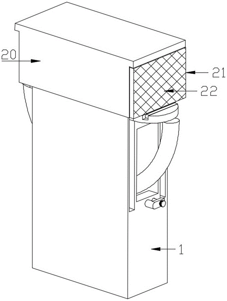
图1为本发明结构示意图;Fig. 1 is a structural representation of the present invention;
图2为本发明结构局部剖示意图;Fig. 2 is a partial sectional view of the structure of the present invention;
图3为本发明固定底座结构示意图;Fig. 3 is a schematic diagram of the structure of the fixed base of the present invention;
图4为图2中A处放大示意图;Figure 4 is an enlarged schematic view of A in Figure 2;
图5为图4中B处放大示意图;Fig. 5 is the enlarged schematic diagram of place B in Fig. 4;
图6为本发明移动板与安装架连接结构示意图。Fig. 6 is a schematic diagram of the connection structure between the mobile plate and the mounting frame of the present invention.
图中:固定底座1、通槽2、导向槽3、转动杆4、转动手柄5、顶持杆6、移动板7、放置槽8、挡板9、收纳槽10、弹力板11、卡槽12、导向斜块13、连接板14、置放槽15、限位块16、弹簧一17、弹簧二18、拉杆19、安装架20、警示牌21、凸条22、导向块23、顶持杆24。In the figure:
具体实施方式Detailed ways
下面将结合本发明实施例中的附图,对本发明实施例中的技术方案进行清楚、完整地描述,显然,所描述的实施例仅仅是本发明一部分实施例,而不是全部的实施例。基于本发明中的实施例,本领域普通技术人员在没有做出创造性劳动前提下所获得的所有其他实施例,都属于本发明保护的范围。The following will clearly and completely describe the technical solutions in the embodiments of the present invention with reference to the accompanying drawings in the embodiments of the present invention. Obviously, the described embodiments are only some, not all, embodiments of the present invention. Based on the embodiments of the present invention, all other embodiments obtained by persons of ordinary skill in the art without making creative efforts belong to the protection scope of the present invention.
实施例一Embodiment one
请参阅图1至图6,本发明提供一种技术方案:一种道路桥梁施工用安全警示装置,所述用于道路桥梁施工用安全警示装置包括:固定底座1,固定底座1的表面开设有通槽2,通槽2的表面转动连接有转动杆4,转动杆4的表面设置有顶持杆6,通槽2的表面设置有移动板7,且顶持杆6与移动板7接触;挡板9,转动连接在移动板7的表面,移动板7的表面设置有警示牌21,且挡板9与警示牌21接触;Please refer to Figures 1 to 6, the present invention provides a technical solution: a safety warning device for road and bridge construction, the safety warning device for road and bridge construction includes: a
转动手柄5带动顶持杆6转动的过程当中,移动板7沿着导向槽3移动,即可对警示牌21整体高度进行调整,调整好后的转动杆4通过拉杆19一段位于固定底座1表面对应的孔内即可;当连接板14位于卡槽12内时,推动顶持杆24顶持连接板14缩回置放槽15内,在弹力板11的作用下,挡板9从放置槽8内弹出,挡板9与警示牌21表面的凸条22配合,对警示牌21进行限位,警示牌21整体拆卸方便;During the process of turning the
实施例二Embodiment two
在实施例一的基础上,为了实现对警示牌21高度的调整,通槽2呈方形通槽结构,顶持杆6为截面呈圆形的弧形板状结构,且顶持杆6的两端位于固定底座1的外部,转动杆4的表面设置有转动手柄5,转动手柄5呈方形板状结构,转动手柄5的表面插接有拉杆19,拉杆19呈“T”字形柱体结构,拉杆19的一端位于固定底座1表面与之对应的孔内,且转动手柄5与拉杆19的表面之间设置有弹簧,弹簧套设在拉杆19的表面,固定底座1的表面开设有导向槽3,导向槽3呈方形槽体结构,导向槽3设置有两组,一组导向槽3包括两个导向槽3,两个导向槽3关于固定底座1一端中心对称分布,两组导向槽3关于固定底座1的中心对称分布,移动板7呈半圆形板状结构,移动板7的表面一体成型有导向块23,导向块23设置有两组,两组通槽2关于移动板7的中心对称分布,且导向块23滑动连接在导向槽3的表面,转动手柄5带动转动杆4表面的顶持杆6转动,顶持杆6转动的过程当中,移动板7沿着导向槽3移动,即可对警示牌21整体高度进行调整,调整好后的转动杆4通过拉杆19一段位于固定底座1表面对应的孔内即可;On the basis of
实施例三Embodiment Three
在实施例二的基础上,为了实现对警示牌21的固定,移动板7的表面开设有放置槽8,放置槽8呈方形槽体结构,挡板9转动连接在放置槽8的表面,挡板9呈方形板状结构,挡板9的表面设置有连接板14,连接板14的表面开设有置放槽15,置放槽15的表面滑动连接有限位块16,且置放槽15与限位块16的表面之间设置有弹簧一17,移动板7的表面开设有卡槽12,卡槽12呈方形槽体结构,卡槽12的表面设置有导向斜块13,且连接板14位于卡槽12内,卡槽12的表面插接有顶持杆24,顶持杆24呈“T”字形柱体结构,且顶持杆24的一端与限位块16接触,限位块16与导向斜块13接触,限位块16的表面开设有导向斜面,移动板7与顶持杆24的表面之间设置有弹簧二18,弹簧二18套设在顶持杆24的表面,移动板7的表面开设有收纳槽10,收纳槽10的表面设置有弹力板11,弹力板11呈弧形板状结构,且弹力板11的一端固定在挡板9的表面,警示牌21的表面设置有凸条22,且凸条22设置有两组,其余一组凸条22设于挡板9与警示牌21相接触的表面,当连接板14位于卡槽12内时,推动顶持杆24顶持连接板14缩回置放槽15内,在弹力板11的作用下,挡板9从放置槽8内弹出,挡板9与警示牌21表面的凸条22配合,对警示牌21进行限位,警示牌21整体拆卸方便;On the basis of
实际使用时,转动手柄5带动转动杆4表面的顶持杆6转动,顶持杆6转动的过程当中,移动板7沿着导向槽3移动,即可对警示牌21整体高度进行调整,调整好后的转动杆4通过拉杆19一段位于固定底座1表面对应的孔内即可;During actual use, the
当连接板14位于卡槽12内时,推动顶持杆24顶持连接板14缩回置放槽15内,在弹力板11的作用下,挡板9从放置槽8内弹出,挡板9与警示牌21表面的凸条22配合,对警示牌21进行限位,警示牌21整体拆卸方便。When the connecting
尽管已经示出和描述了本发明的实施例,对于本领域的普通技术人员而言,可以理解在不脱离本发明的原理和精神的情况下可以对这些实施例进行多种变化、修改、替换和变型,本发明的范围由所附权利要求及其等同物限定。Although the embodiments of the present invention have been shown and described, those skilled in the art can understand that various changes, modifications and substitutions can be made to these embodiments without departing from the principle and spirit of the present invention. and modifications, the scope of the invention is defined by the appended claims and their equivalents.
Claims (10)
Priority Applications (1)
| Application Number | Priority Date | Filing Date | Title |
|---|---|---|---|
| CN202210999535.9A CN115341493A (en) | 2022-08-19 | 2022-08-19 | Safety warning device is used in road and bridge construction |
Applications Claiming Priority (1)
| Application Number | Priority Date | Filing Date | Title |
|---|---|---|---|
| CN202210999535.9A CN115341493A (en) | 2022-08-19 | 2022-08-19 | Safety warning device is used in road and bridge construction |
Publications (1)
| Publication Number | Publication Date |
|---|---|
| CN115341493A true CN115341493A (en) | 2022-11-15 |
Family
ID=83954167
Family Applications (1)
| Application Number | Title | Priority Date | Filing Date |
|---|---|---|---|
| CN202210999535.9A Pending CN115341493A (en) | 2022-08-19 | 2022-08-19 | Safety warning device is used in road and bridge construction |
Country Status (1)
| Country | Link |
|---|---|
| CN (1) | CN115341493A (en) |
Cited By (1)
| Publication number | Priority date | Publication date | Assignee | Title |
|---|---|---|---|---|
| CN120716569A (en) * | 2025-09-03 | 2025-09-30 | 中铁建大桥工程局集团靖江重工有限公司 | A transverse safety warning device for a beam moving machine |
Citations (8)
| Publication number | Priority date | Publication date | Assignee | Title |
|---|---|---|---|---|
| CN205662867U (en) * | 2016-05-25 | 2016-10-26 | 国网山东省电力公司平度市供电公司 | Electric power construction safety developments information warning sign |
| CN107288051A (en) * | 2017-08-14 | 2017-10-24 | 严晓梦 | A kind of novel bridge warns board apparatus |
| CN209538795U (en) * | 2018-11-13 | 2019-10-25 | 薛来铖 | A kind of detachable protective fence of road and bridge construction |
| CN210459007U (en) * | 2019-06-19 | 2020-05-05 | 宜春市交通公路工程建设有限公司 | A multifunctional bridge construction warning device |
| CN210984059U (en) * | 2019-12-20 | 2020-07-10 | 贾长金 | Adjustment mechanism of warning sign for construction |
| WO2021031181A1 (en) * | 2019-08-21 | 2021-02-25 | 南京唐壹信息科技有限公司 | Temporary safety warning device for use in bridge construction |
| CN213173413U (en) * | 2020-08-18 | 2021-05-11 | 安徽浩源建设工程有限公司 | Municipal administration public works construction warning structure |
| CN213448195U (en) * | 2020-09-16 | 2021-06-15 | 张笛 | Warning device for electromechanical engineering construction |
-
2022
- 2022-08-19 CN CN202210999535.9A patent/CN115341493A/en active Pending
Patent Citations (8)
| Publication number | Priority date | Publication date | Assignee | Title |
|---|---|---|---|---|
| CN205662867U (en) * | 2016-05-25 | 2016-10-26 | 国网山东省电力公司平度市供电公司 | Electric power construction safety developments information warning sign |
| CN107288051A (en) * | 2017-08-14 | 2017-10-24 | 严晓梦 | A kind of novel bridge warns board apparatus |
| CN209538795U (en) * | 2018-11-13 | 2019-10-25 | 薛来铖 | A kind of detachable protective fence of road and bridge construction |
| CN210459007U (en) * | 2019-06-19 | 2020-05-05 | 宜春市交通公路工程建设有限公司 | A multifunctional bridge construction warning device |
| WO2021031181A1 (en) * | 2019-08-21 | 2021-02-25 | 南京唐壹信息科技有限公司 | Temporary safety warning device for use in bridge construction |
| CN210984059U (en) * | 2019-12-20 | 2020-07-10 | 贾长金 | Adjustment mechanism of warning sign for construction |
| CN213173413U (en) * | 2020-08-18 | 2021-05-11 | 安徽浩源建设工程有限公司 | Municipal administration public works construction warning structure |
| CN213448195U (en) * | 2020-09-16 | 2021-06-15 | 张笛 | Warning device for electromechanical engineering construction |
Cited By (1)
| Publication number | Priority date | Publication date | Assignee | Title |
|---|---|---|---|---|
| CN120716569A (en) * | 2025-09-03 | 2025-09-30 | 中铁建大桥工程局集团靖江重工有限公司 | A transverse safety warning device for a beam moving machine |
Similar Documents
| Publication | Publication Date | Title |
|---|---|---|
| CN109272861B (en) | A reminder device for easy replacement of warning signs for power supply construction | |
| CN215829276U (en) | An easy-to-adjust municipal bridge support device | |
| CN211228265U (en) | Municipal administration rail guard | |
| CN208280047U (en) | A kind of municipal administration folding warning sign being convenient for carrying | |
| CN216952834U (en) | A high security LED street light | |
| CN221927413U (en) | Guide sign convenient to installation is changed | |
| CN217870135U (en) | Multifunctional warning device for traffic facility engineering | |
| CN220598273U (en) | A kind of protective fence for municipal engineering urban roads | |
| CN211336254U (en) | Bicycle parking device | |
| CN217267060U (en) | Traffic sign convenient to remove | |
| CN205711872U (en) | A kind of crashproof road guard of new type of safe flexible buffer | |
| CN214168841U (en) | A warning sign device for road and bridge that is conducive to display | |
| CN219157467U (en) | Bridge height limiting device | |
| CN211472246U (en) | A kind of warning equipment for road construction | |
| CN217203713U (en) | Municipal administration public works construction warning structure | |
| CN219349705U (en) | Sign installation device for track traffic | |
| CN219410670U (en) | Traffic foundation safety structure | |
| CN221895626U (en) | Highway temporary indication board convenient to it is fixed | |
| CN219483701U (en) | Propaganda column glass belt cleaning device for traffic highway | |
| CN221822778U (en) | Safety reminding assembly for road and bridge construction | |
| CN213867467U (en) | A kind of fixing device for traffic safety sign | |
| CN221501791U (en) | Firm type stand is used to urban road | |
| CN216517261U (en) | Protection device for be used for road bridge construction | |
| CN222614979U (en) | A municipal construction road warning fence | |
| CN219450525U (en) | Urban road safety height limiting equipment |
Legal Events
| Date | Code | Title | Description |
|---|---|---|---|
| PB01 | Publication | ||
| PB01 | Publication | ||
| SE01 | Entry into force of request for substantive examination | ||
| SE01 | Entry into force of request for substantive examination | ||
| RJ01 | Rejection of invention patent application after publication | ||
| RJ01 | Rejection of invention patent application after publication |
Application publication date: 20221115 |