CN115325876A - Novel heat storage device and manufacturing method - Google Patents
Novel heat storage device and manufacturing method Download PDFInfo
- Publication number
- CN115325876A CN115325876A CN202210735149.9A CN202210735149A CN115325876A CN 115325876 A CN115325876 A CN 115325876A CN 202210735149 A CN202210735149 A CN 202210735149A CN 115325876 A CN115325876 A CN 115325876A
- Authority
- CN
- China
- Prior art keywords
- heat storage
- filter
- fixedly connected
- motor
- liquid
- Prior art date
- Legal status (The legal status is an assumption and is not a legal conclusion. Google has not performed a legal analysis and makes no representation as to the accuracy of the status listed.)
- Pending
Links
Images


Classifications
-
- F—MECHANICAL ENGINEERING; LIGHTING; HEATING; WEAPONS; BLASTING
- F28—HEAT EXCHANGE IN GENERAL
- F28G—CLEANING OF INTERNAL OR EXTERNAL SURFACES OF HEAT-EXCHANGE OR HEAT-TRANSFER CONDUITS, e.g. WATER TUBES OR BOILERS
- F28G3/00—Rotary appliances
- F28G3/04—Rotary appliances having brushes
-
- B—PERFORMING OPERATIONS; TRANSPORTING
- B08—CLEANING
- B08B—CLEANING IN GENERAL; PREVENTION OF FOULING IN GENERAL
- B08B9/00—Cleaning hollow articles by methods or apparatus specially adapted thereto
- B08B9/08—Cleaning containers, e.g. tanks
- B08B9/087—Cleaning containers, e.g. tanks by methods involving the use of tools, e.g. brushes, scrapers
-
- B—PERFORMING OPERATIONS; TRANSPORTING
- B08—CLEANING
- B08B—CLEANING IN GENERAL; PREVENTION OF FOULING IN GENERAL
- B08B9/00—Cleaning hollow articles by methods or apparatus specially adapted thereto
- B08B9/08—Cleaning containers, e.g. tanks
- B08B9/093—Cleaning containers, e.g. tanks by the force of jets or sprays
-
- F—MECHANICAL ENGINEERING; LIGHTING; HEATING; WEAPONS; BLASTING
- F28—HEAT EXCHANGE IN GENERAL
- F28G—CLEANING OF INTERNAL OR EXTERNAL SURFACES OF HEAT-EXCHANGE OR HEAT-TRANSFER CONDUITS, e.g. WATER TUBES OR BOILERS
- F28G15/00—Details
- F28G15/003—Control arrangements
-
- F—MECHANICAL ENGINEERING; LIGHTING; HEATING; WEAPONS; BLASTING
- F28—HEAT EXCHANGE IN GENERAL
- F28G—CLEANING OF INTERNAL OR EXTERNAL SURFACES OF HEAT-EXCHANGE OR HEAT-TRANSFER CONDUITS, e.g. WATER TUBES OR BOILERS
- F28G15/00—Details
- F28G15/04—Feeding and driving arrangements, e.g. power operation
-
- F—MECHANICAL ENGINEERING; LIGHTING; HEATING; WEAPONS; BLASTING
- F28—HEAT EXCHANGE IN GENERAL
- F28G—CLEANING OF INTERNAL OR EXTERNAL SURFACES OF HEAT-EXCHANGE OR HEAT-TRANSFER CONDUITS, e.g. WATER TUBES OR BOILERS
- F28G9/00—Cleaning by flushing or washing, e.g. with chemical solvents
-
- F—MECHANICAL ENGINEERING; LIGHTING; HEATING; WEAPONS; BLASTING
- F28—HEAT EXCHANGE IN GENERAL
- F28G—CLEANING OF INTERNAL OR EXTERNAL SURFACES OF HEAT-EXCHANGE OR HEAT-TRANSFER CONDUITS, e.g. WATER TUBES OR BOILERS
- F28G15/00—Details
- F28G2015/006—Arrangements for processing a cleaning fluid after use, e.g. filtering and recycling
-
- Y—GENERAL TAGGING OF NEW TECHNOLOGICAL DEVELOPMENTS; GENERAL TAGGING OF CROSS-SECTIONAL TECHNOLOGIES SPANNING OVER SEVERAL SECTIONS OF THE IPC; TECHNICAL SUBJECTS COVERED BY FORMER USPC CROSS-REFERENCE ART COLLECTIONS [XRACs] AND DIGESTS
- Y02—TECHNOLOGIES OR APPLICATIONS FOR MITIGATION OR ADAPTATION AGAINST CLIMATE CHANGE
- Y02E—REDUCTION OF GREENHOUSE GAS [GHG] EMISSIONS, RELATED TO ENERGY GENERATION, TRANSMISSION OR DISTRIBUTION
- Y02E60/00—Enabling technologies; Technologies with a potential or indirect contribution to GHG emissions mitigation
- Y02E60/14—Thermal energy storage
Landscapes
- Engineering & Computer Science (AREA)
- Mechanical Engineering (AREA)
- Chemical & Material Sciences (AREA)
- Combustion & Propulsion (AREA)
- General Engineering & Computer Science (AREA)
- Heat-Pump Type And Storage Water Heaters (AREA)
Abstract
本发明公开了一种新型储热装置及制作方法,包括储热罐,所述控制设备本体前方表面一侧安装有显示屏,所述控制设备本体下表面一侧设置有热水管,所述控制设备本体下表面另一侧设置有冷水管,所述过滤罐内安装有过滤组件,所述过滤组件内安装有叶轮,所述储热罐远离过滤罐一侧安装有电热丝加热板,所述箱体内安装有移动组件,所述移动组件上安装有清除水垢组件,所述清除水垢组件上安装有一号滤板和清洁毛刷,本发明通过二号电机带动叶轮旋转,就可以带动储热罐内的液体旋转起来,就可以使叶轮将液体经过限位块之间的缝隙穿过去,带动液体高速旋转起来,液体经过二号滤板可以对液体中的杂质进行过滤。
The invention discloses a novel heat storage device and a manufacturing method, comprising a heat storage tank, a display screen is installed on one side of the front surface of the control device body, a hot water pipe is installed on the lower surface side of the control device body, and the A cold water pipe is arranged on the other side of the lower surface of the control device body, a filter assembly is installed in the filter tank, an impeller is installed in the filter assembly, and an electric heating wire heating plate is installed on the side of the heat storage tank away from the filter tank. A moving assembly is installed in the box, a scale removing assembly is installed on the moving assembly, a No. 1 filter plate and a cleaning brush are installed on the moving assembly, and the No. 2 motor drives the impeller to rotate, which can drive the heat storage. When the liquid in the tank rotates, the impeller can pass the liquid through the gap between the limit blocks, driving the liquid to rotate at a high speed, and the liquid can filter the impurities in the liquid through the No. 2 filter plate.
Description
技术领域technical field
本发明属于储热技术领域,尤其涉及一种新型储热装置及制作方法。The invention belongs to the technical field of heat storage, and in particular relates to a novel heat storage device and a manufacturing method.
背景技术Background technique
热能储存装置就是储备热能的装置。一种储存热能,可能是储存太阳能的装置,为此申请号:CN201110257561.6,公开了一种用于储能装置的空气阀及储能装置,所述储能装置包括用于储能装置的空气阀。所述用于储能装置的空气阀包括:本体,包括彼此隔开地设置的气体入口和气体出口;以及活塞,包含在本体的内部中,并阻断或开启气体入口与气体出口之间的通路,其中,当储能装置的内部中的压力由于其中的气体产生而增大时,活塞移动以开启气体入口与气体出口之间的通路,并且当储能装置的内部中的压力由于储能装置的内部中的气体的排放或者气体产生的减少而减小时,活塞移动以阻断气体入口与气体出口之间的通路。A thermal energy storage device is a device that stores thermal energy. A device for storing thermal energy, possibly solar energy, for which application number: CN201110257561.6 discloses an air valve for an energy storage device and an energy storage device, the energy storage device includes a air valve. The air valve for an energy storage device includes: a body including a gas inlet and a gas outlet arranged apart from each other; and a piston contained in the interior of the body and blocking or opening the gas inlet and the gas outlet. passage, wherein when the pressure in the interior of the energy storage device increases due to gas generation therein, the piston moves to open the passage between the gas inlet and the gas outlet, and when the pressure in the interior of the energy storage device increases due to the stored energy When the discharge of gas or the reduction of gas generation in the interior of the device decreases, the piston moves to block the passage between the gas inlet and the gas outlet.
上述技术存在的问题是:储热装置在长时间时候储热装置内部会存留大量的水垢,这些水质会影响到使用者的使用效率严重会发生水管堵塞的现象和由于使用的是地下水这些水如果不对其进行过滤而是直接使用的话,会造成一些细菌感染的问题。The problem with the above technology is that the heat storage device will retain a large amount of scale inside the heat storage device for a long time. If it is used directly without filtering it, it will cause some problems of bacterial infection.
发明内容Contents of the invention
针对现有技术存在的问题,本发明提供了一种新型储热装置及制作方法,具备对储能装置内的水垢进行清洁和对水源进行过滤的优点,解决了现有储热装置在长时间时候储热装置内部会存留大量的水垢,这些水质会影响到使用者的使用效率严重会发生水管堵塞的现象和由于使用的是地下水这些水如果不对其进行过滤而是直接使用的话,会造成一些细菌感染的问题。Aiming at the problems existing in the prior art, the present invention provides a novel heat storage device and a manufacturing method, which has the advantages of cleaning the scale in the energy storage device and filtering the water source, and solves the problem that the existing heat storage device has a long time Sometimes there will be a lot of scale inside the heat storage device, and the water quality will affect the user's use efficiency. Seriously, the water pipes will be blocked, and because the groundwater is used, if the water is not filtered but used directly, it will cause some problems. The problem of bacterial infection.
本发明是这样实现的,一种新型储热装置及制作方法,包括储热罐,所述储热罐上表面连接有箱体,所述储热罐一侧连接有过滤罐,所述储热罐表面下方两侧设置有排污口,所述储热罐表面下方固定连接有控制设备本体,所述控制设备本体前方表面一侧安装有显示屏,所述控制设备本体下表面一侧设置有热水管,所述控制设备本体下表面另一侧设置有冷水管,所述过滤罐内安装有过滤组件,所述过滤组件内安装有叶轮,所述储热罐远离过滤罐一侧安装有电热丝加热板,所述箱体内安装有移动组件,所述移动组件上安装有清除水垢组件,所述清除水垢组件上安装有一号滤板和清洁毛刷。The present invention is achieved in this way, a novel heat storage device and its manufacturing method, comprising a heat storage tank, the upper surface of the heat storage tank is connected with a box body, one side of the heat storage tank is connected with a filter tank, and the heat storage tank Sewage outlets are arranged on both sides of the bottom of the tank surface. The control equipment body is fixedly connected to the bottom of the heat storage tank. A display screen is installed on the front surface of the control equipment body. A water pipe, a cold water pipe is provided on the other side of the lower surface of the control device body, a filter assembly is installed in the filter tank, an impeller is installed in the filter assembly, and an electric heater is installed on the side of the heat storage tank away from the filter tank. A wire heating plate, a moving assembly is installed in the box, a scale removing assembly is installed on the moving assembly, and a No. 1 filter plate and a cleaning brush are installed on the scale removing assembly.
作为本发明优选的,所述移动组件包括三号电机,所述三号电机固定连接于箱体内壁一侧,所述三号电机的输出轴固定连接有螺纹杆,所述螺纹杆通过螺纹啮合连接有螺纹圈,所述螺纹圈设置于活动块中部。As preferred in the present invention, the moving assembly includes a No. 3 motor, and the No. 3 motor is fixedly connected to one side of the inner wall of the box. The output shaft of the No. 3 motor is fixedly connected to a threaded rod, and the threaded rod is engaged by threads A threaded ring is connected, and the threaded ring is arranged in the middle of the movable block.
作为本发明优选的,所述活动块两侧活动贯穿有限位杆,所述限位杆固定连接于箱体内壁支架,所述活动块下表面两侧固定连接有二号连接杆,两侧所述二号连接杆下端固定连接有清除水垢组件。As preferred in the present invention, the two sides of the movable block move through the limit rod, and the limit rod is fixedly connected to the bracket on the inner wall of the box, and the two sides of the lower surface of the movable block are fixedly connected with the second connecting rod. The lower end of the No. 2 connecting rod is fixedly connected with a scale removal assembly.
作为本发明优选的,所述过滤组件包括固定环,所述固定环固定连接于过滤罐内壁支架,所述固定环内壁固定连接有若干个均匀分布的限位块,靠近所述固定环一侧设置有二号滤板。As preferred in the present invention, the filter assembly includes a fixed ring, the fixed ring is fixedly connected to the inner wall support of the filter tank, and the inner wall of the fixed ring is fixedly connected with several evenly distributed limiting blocks, which are close to the side of the fixed ring There is a No. 2 filter plate.
作为本发明优选的,所述固定环中部设置有叶轮,所述叶轮一侧固定连接有二号电机,所述二号电机通过固定支架固定连接于过滤罐内壁。As preferred in the present invention, an impeller is arranged in the middle of the fixing ring, and a No. 2 motor is fixedly connected to one side of the impeller, and the No. 2 motor is fixedly connected to the inner wall of the filter tank through a fixing bracket.
作为本发明优选的,所述清除水垢组件包括固定板,所述固定板内壁通过一号连接杆固定连接有一号滤板,所述固定板另一侧固定连接有一号环形滑轨,所述一号环形滑轨上安装有齿轮圈。As preferred in the present invention, the descaling assembly includes a fixed plate, the inner wall of the fixed plate is fixedly connected with a No. 1 filter plate through a No. 1 connecting rod, and the other side of the fixed plate is fixedly connected with a No. A gear ring is installed on the number ring slide rail.
作为本发明优选的,所述齿轮圈通过卡齿啮合连接有齿轮,所述齿轮固定连接于一号电机的输出轴,所述一号电机固定连接于活动块下表面。As a preferred embodiment of the present invention, the gear ring is connected to a gear through snap-tooth engagement, and the gear is fixedly connected to the output shaft of the No. 1 motor, and the No. 1 motor is fixedly connected to the lower surface of the movable block.
作为本发明优选的,所述齿轮圈另一侧固定转动安装有若干个均匀分布的安装杆,每个所述安装杆表面固定套设有清洁毛刷,每个所述安装杆另一端安装于二号环形滑轨内,所述二号环形滑轨另一侧固定连接有集水板。As preferred in the present invention, the other side of the gear ring is fixedly and rotatably installed with several evenly distributed installation rods, each of the surface of the installation rods is fixed with a cleaning brush, and the other end of each of the installation rods is installed on the In the No. 2 annular slide rail, the other side of the No. 2 annular slide rail is fixedly connected with a water collecting plate.
作为本发明优选的,包括以下步骤:Preferably as the present invention, comprise the following steps:
S1、首先通过电热丝加热板将储热罐内的液体加热,随后启动二号电机带动叶轮旋转,就可以带动储热罐内的液体旋转起来;S1. First, heat the liquid in the heat storage tank through the electric heating plate, and then start the No. 2 motor to drive the impeller to rotate, which can drive the liquid in the heat storage tank to rotate;
S2、随后叶轮将液体经过限位块之间的缝隙穿过去,就可以使液体高速旋转起来,液体经过二号滤板可以对液体中的杂质进行过滤;S2. Then the impeller passes the liquid through the gap between the limit blocks, so that the liquid can be rotated at a high speed, and the liquid can filter the impurities in the liquid through the No. 2 filter plate;
S3、随后启动一号电机通过齿轮带动齿轮圈旋转起来,就可以带动清洁毛刷旋转起来,就可以对储热罐内壁的水垢进行清除;S3, then start the No. 1 motor to drive the gear ring to rotate through the gear, which can drive the cleaning brush to rotate, and the scale on the inner wall of the heat storage tank can be removed;
S4、随后通过齿轮圈一侧设置有集水板,集水板可以对经过的液体进行收集经过一号滤板,达到对水垢集中收集的左右,就可以经过排污口对水垢进行清理;S4. Then, a water collecting plate is installed on one side of the gear ring. The water collecting plate can collect the passing liquid and pass through the No. 1 filter plate, so as to reach the left and right of centralized collection of scale, and then the scale can be cleaned through the sewage outlet;
S5、最后通过三号电机带动螺纹杆旋转,螺纹杆和螺纹圈的配合就可以使活动块沿着螺纹杆左右移动,就可以带动清除水垢组件对储热罐的内壁进行清洁。S5. Finally, the No. 3 motor drives the threaded rod to rotate, and the cooperation of the threaded rod and the threaded ring can make the movable block move left and right along the threaded rod, and the descaling component can be driven to clean the inner wall of the heat storage tank.
与现有技术相比,本发明的有益效果如下:Compared with the prior art, the beneficial effects of the present invention are as follows:
1、本发明通过三号电机带动螺纹杆旋转,由于螺纹杆通过螺纹啮合连接有螺纹圈,螺纹圈设置于活动块内部,就可以带动活动块沿着螺纹杆前后移动。1. In the present invention, the No. 3 motor drives the threaded rod to rotate. Since the threaded rod is connected with a threaded ring through thread engagement, and the threaded ring is arranged inside the movable block, the movable block can be driven to move back and forth along the threaded rod.
2、本发明通过活动块两侧活动贯穿有限位杆,就可以对活动块起到限位的作用,再由于活动块下表面通过二号连接杆连接清除水垢组件,就可以带动清除水垢组件沿着出水管内部左右移动,对内壁的水垢进行清洁。2. The present invention can move through the limit rods on both sides of the movable block to limit the position of the movable block, and because the lower surface of the movable block is connected to the scale removal component through the No. 2 connecting rod, it can drive the scale removal component along the Move left and right along the inside of the outlet pipe to clean the scale on the inner wall.
3、本发明通过二号电机带动叶轮旋转,就可以带动储热罐内的液体旋转起来,就可以使叶轮将液体经过限位块之间的缝隙穿过去,带动液体高速旋转起来,液体经过二号滤板可以对液体中的杂质进行过滤。3. The invention drives the impeller to rotate through the No. 2 motor, which can drive the liquid in the heat storage tank to rotate, and the impeller can pass the liquid through the gap between the limit blocks, driving the liquid to rotate at a high speed, and the liquid passes through the two No. filter plate can filter the impurities in the liquid.
4、本发明通过二号电机带动叶轮旋转,就可以带动储热罐内的液体旋转起来,就可以使叶轮将液体经过限位块之间的缝隙穿过去,带动液体高速旋转起来,液体经过二号滤板可以对液体中的杂质进行过滤。4. The invention drives the impeller to rotate through the No. 2 motor, which can drive the liquid in the heat storage tank to rotate, and the impeller can pass the liquid through the gap between the limit blocks, driving the liquid to rotate at a high speed, and the liquid passes through the two No. filter plate can filter the impurities in the liquid.
5、本发明通过一号电机带动齿轮旋转,由于齿轮通过卡齿啮合连接有齿轮圈,就可以带动齿轮圈旋转起来。5. In the present invention, the No. 1 motor drives the gear to rotate, and since the gear is connected to the gear ring through the locking teeth, the gear ring can be driven to rotate.
6、本发明通过齿轮圈一侧表面转动安装有安装杆,由于安装杆另一端安装有一号环形滑轨,而安装杆表面套设有清洁毛刷,就可以对储热罐内壁的水垢进行清洁。6. In the present invention, a mounting rod is installed by rotating the surface of one side of the gear ring. Since the other end of the mounting rod is installed with a No. 1 annular slide rail, and the surface of the mounting rod is covered with a cleaning brush, the scale on the inner wall of the heat storage tank can be cleaned. .
附图说明Description of drawings
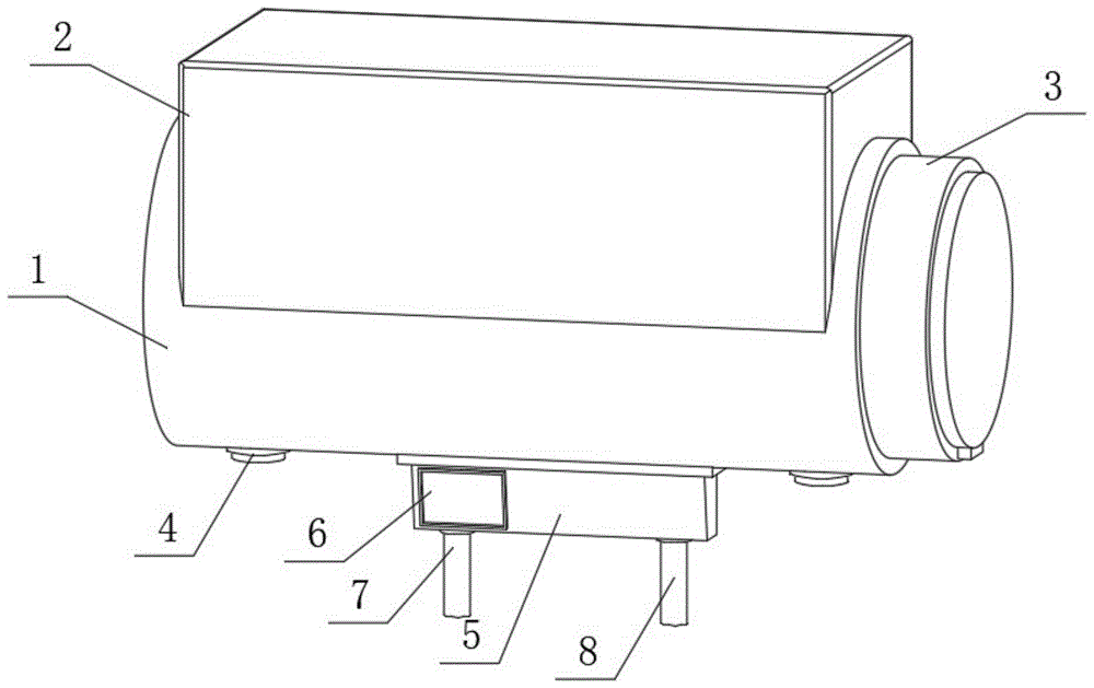
图1是本发明实施例提供的整体结构示意图;FIG. 1 is a schematic diagram of the overall structure provided by an embodiment of the present invention;
图2是本发明实施例提供的储热罐剖面结构示意图;Fig. 2 is a schematic cross-sectional structure diagram of a heat storage tank provided by an embodiment of the present invention;
图3是本发明实施例提供的过滤组件结构示意图;Fig. 3 is a schematic structural diagram of a filter assembly provided by an embodiment of the present invention;
图4是本发明实施例提供的移动组件结构示意图;Fig. 4 is a schematic structural diagram of a mobile component provided by an embodiment of the present invention;
图5是本发明实施例提供的清除水垢组件结构示意图。Fig. 5 is a schematic structural diagram of a scale removal component provided by an embodiment of the present invention.
图中:1、储热罐;2、箱体;3、过滤罐;4、排污口;5、控制设备本体;6、显示屏;7、热水管;8、冷水管;9、移动组件;10、电热丝加热板;11、连接杆;12、清除水垢组件;13、一号滤板;14、叶轮;15、清洁毛刷;16、过滤组件;201、集水板;202、一号环形滑轨;203、安装杆;204、齿轮圈;205、二号环形滑轨;206、固定板;207、一号连接杆;208、一号电机;209、齿轮;601、二号滤板;602、固定环;603、限位块;604、固定支架;605、二号电机;901、三号电机;902、螺纹杆;903、螺纹圈;904、限位杆;905、活动块;906、二号连接杆。In the figure: 1. Heat storage tank; 2. Box body; 3. Filter tank; 4. Sewage outlet; 5. Control device body; 6. Display screen; 7. Hot water pipe; 8. Cold water pipe; 9. Mobile components ;10, electric heating wire heating plate; 11, connecting rod; 12, scale removal component; 13, No. 1 filter plate; 14, impeller; 15, cleaning brush; 16, filter assembly; 201, water collecting plate; 202, one 203, installation rod; 204, gear ring; 205, No. 2 annular slide rail; 206, fixed plate; 207, No. 1 connecting rod; 208, No. 1 motor; 209, gear; 601, No. 2 filter Plate; 602, fixed ring; 603, limit block; 604, fixed bracket; 605, No. 2 motor; 901, No. 3 motor; 902, threaded rod; 903, threaded circle; 904, limit rod; ; 906, No. two connecting rod.
具体实施方式Detailed ways
为能进一步了解本发明的本发明内容、特点及功效,兹例举以下实施例,并配合附图详细说明如下。In order to further understand the content, characteristics and effects of the present invention, the following examples are given, and detailed descriptions are given below with reference to the accompanying drawings.
下面结合附图对本发明的结构作详细的描述。The structure of the present invention will be described in detail below in conjunction with the accompanying drawings.
如图1至图5所示,一种新型储热装置及制作方法,包括储热罐1,所述储热罐1上表面连接有箱体2,所述储热罐1一侧连接有过滤罐3,所述储热罐1表面下方两侧设置有排污口4,所述储热罐1表面下方固定连接有控制设备本体5,所述控制设备本体5前方表面一侧安装有显示屏6,所述控制设备本体5下表面一侧设置有热水管7,所述控制设备本体5下表面另一侧设置有冷水管8,所述过滤罐3内安装有过滤组件16,所述过滤组件16内安装有叶轮14,所述储热罐1远离过滤罐3一侧安装有电热丝加热板10,所述箱体2内安装有移动组件9,所述移动组件9上安装有清除水垢组件12,所述清除水垢组件12上安装有一号滤板13和清洁毛刷15。As shown in Figures 1 to 5, a new type of heat storage device and manufacturing method includes a
参考图2,所述移动组件9包括三号电机901,所述三号电机901固定连接于箱体2内壁一侧,所述三号电机901的输出轴固定连接有螺纹杆902,所述螺纹杆902通过螺纹啮合连接有螺纹圈903,所述螺纹圈903设置于活动块905中部。Referring to Fig. 2, the moving
采用上述方案:通过三号电机901带动螺纹杆902旋转,由于螺纹杆902通过螺纹啮合连接有螺纹圈903,螺纹圈903设置于活动块905内部,就可以带动活动块905沿着螺纹杆902前后移动。Adopt the above scheme: drive the threaded
参考图2,所述活动块905两侧活动贯穿有限位杆904,所述限位杆904固定连接于箱体2内壁支架,所述活动块905下表面两侧固定连接有二号连接杆906,两侧所述二号连接杆906下端固定连接有清除水垢组件12。Referring to Fig. 2, both sides of the
采用上述方案:通过活动块905两侧活动贯穿有限位杆904,就可以对活动块905起到限位的作用,再由于活动块905下表面通过二号连接杆906连接清除水垢组件12,就可以带动清除水垢组件12沿着出水管1内部左右移动,对内壁的水垢进行清洁。Adopt the above-mentioned scheme: move through the limiting
参考图3,所述过滤组件16包括固定环602,所述固定环602固定连接于过滤罐3内壁支架,所述固定环602内壁固定连接有若干个均匀分布的限位块603,靠近所述固定环602一侧设置有二号滤板601,所述固定环602中部设置有叶轮14,所述叶轮14一侧固定连接有二号电机605,所述二号电机605通过固定支架604固定连接于过滤罐3内壁。Referring to Fig. 3, the
采用上述方案:通过二号电机605带动叶轮14旋转,就可以带动储热罐1内的液体旋转起来,就可以使叶轮14将液体经过限位块603之间的缝隙穿过去,带动液体高速旋转起来,液体经过二号滤板601可以对液体中的杂质进行过滤。The above scheme is adopted: the
参考图5,所述清除水垢组件12包括固定板206,所述固定板206内壁通过一号连接杆207固定连接有一号滤板13,所述固定板206另一侧固定连接有一号环形滑轨202,所述一号环形滑轨202上安装有齿轮圈204。Referring to Fig. 5, the
采用上述方案:由于固定板206通过一号连接杆207固定连接有一号滤板13,通过一号滤板13可以对水垢清洁后进行收集,便于对水垢进行清洁,再通过一号环形滑轨202上安装有齿轮圈204,就可以对齿轮圈204起到限位的左右,就可以使齿轮圈204沿着一号环形滑轨202旋转。Adopt the above scheme: Since the fixed
参考图5,所述齿轮圈204通过卡齿啮合连接有齿轮209,所述齿轮209固定连接于一号电机208的输出轴,所述一号电机208固定连接于活动块905下表面。Referring to FIG. 5 , the
采用上述方案:通过一号电机208带动齿轮209旋转,由于齿轮209通过卡齿啮合连接有齿轮圈204,就可以带动齿轮圈204旋转起来。The above scheme is adopted: the
参考图5,所述齿轮圈204另一侧固定转动安装有若干个均匀分布的安装杆203,每个所述安装杆203表面固定套设有清洁毛刷15,每个所述安装杆203另一端安装于二号环形滑轨205内,所述二号环形滑轨205另一侧固定连接有集水板201。With reference to Fig. 5, the other side of the
采用上述方案:通过齿轮圈204一侧表面转动安装有安装杆203,由于安装杆203另一端安装有一号环形滑轨202,而安装杆203表面套设有清洁毛刷15,就可以对储热罐1内壁的水垢进行清洁。The above scheme is adopted: the
参考图1-5,包括以下步骤:Refer to Figure 1-5, including the following steps:
S1、首先通过电热丝加热板10将储热罐1内的液体加热,随后启动二号电机605带动叶轮14旋转,就可以带动储热罐1内的液体旋转起来;S1. Firstly, the liquid in the
S2、随后叶轮14将液体经过限位块603之间的缝隙穿过去,就可以使液体高速旋转起来,液体经过二号滤板601可以对液体中的杂质进行过滤;S2. Then the
S3、随后启动一号电机208通过齿轮209带动齿轮圈204旋转起来,就可以带动清洁毛刷15旋转起来,就可以对储热罐1内壁的水垢进行清除;S3, then start the No. 1
S4、随后通过齿轮圈903一侧设置有集水板201,集水板201可以对经过的液体进行收集经过一号滤板13,达到对水垢集中收集的左右,就可以经过排污口4对水垢进行清理;S4. Then, a
S5、最后通过三号电机901带动螺纹杆902旋转,螺纹杆902和螺纹圈903的配合就可以使活动块905沿着螺纹杆902左右移动,就可以带动清除水垢组件12对储热罐1的内壁进行清洁。S5. Finally, the No. 3
本发明的工作原理:Working principle of the present invention:
在使用时,通过三号电机901带动螺纹杆902旋转,由于螺纹杆902通过螺纹啮合连接有螺纹圈903,螺纹圈903设置于活动块905内部,就可以带动活动块905沿着螺纹杆902前后移动,通过活动块905两侧活动贯穿有限位杆904,就可以对活动块905起到限位的作用,再由于活动块905下表面通过二号连接杆906连接清除水垢组件12,就可以带动清除水垢组件12沿着出水管1内部左右移动,对内壁的水垢进行清洁,通过二号电机605带动叶轮14旋转,就可以带动储热罐1内的液体旋转起来,就可以使叶轮14将液体经过限位块603之间的缝隙穿过去,带动液体高速旋转起来,液体经过二号滤板601可以对液体中的杂质进行过滤,通过二号电机605带动叶轮14旋转,就可以带动储热罐1内的液体旋转起来,就可以使叶轮14将液体经过限位块603之间的缝隙穿过去,带动液体高速旋转起来,液体经过二号滤板601可以对液体中的杂质进行过滤,通过一号电机208带动齿轮209旋转,由于齿轮209通过卡齿啮合连接有齿轮圈204,就可以带动齿轮圈204旋转起来,通过齿轮圈204一侧表面转动安装有安装杆203,由于安装杆203另一端安装有一号环形滑轨202,而安装杆203表面套设有清洁毛刷15,就可以对储热罐1内壁的水垢进行清洁。When in use, the No. 3
综上所述:该一种新型储热装置及制作方法,通过201集水板;202一号环形滑轨;203安装杆;204齿轮圈;205二号环形滑轨;206固定板;207一号连接杆;208一号电机和209齿轮之间的配合,解决了现有储热装置在长时间时候储热装置内部会存留大量的水垢,这些水质会影响到使用者的使用效率严重会发生水管堵塞的现象和由于使用的是地下水这些水如果不对其进行过滤而是直接使用的话,会造成一些细菌感染的问题。To sum up: the new heat storage device and its manufacturing method, through 201 water collecting plate; 202 No. 1 ring slide rail; 203 installation rod; The No. 1 connecting rod; the cooperation between the No. 208 No. 1 motor and the No. 209 gear solves the problem that the existing heat storage device will retain a large amount of scale inside the heat storage device for a long time, and the water quality will affect the user's use efficiency. The phenomenon of clogged water pipes and the use of groundwater will cause some problems of bacterial infection if the water is not filtered but used directly.
需要说明的是,在本文中,诸如第一和第二等之类的关系术语仅仅用来将一个实体或者操作与另一个实体或操作区分开来,而不一定要求或者暗示这些实体或操作之间存在任何这种实际的关系或者顺序。而且,术语“包括”、“包含”或者其任何其他变体意在涵盖非排他性的包含,从而使得包括一系列要素的过程、方法、物品或者设备不仅包括那些要素,而且还包括没有明确列出的其他要素,或者是还包括为这种过程、方法、物品或者设备所固有的要素。It should be noted that in this article, relational terms such as first and second are only used to distinguish one entity or operation from another entity or operation, and do not necessarily require or imply that there is a relationship between these entities or operations. any such actual relationship or order exists between them. Furthermore, the term "comprises", "comprises" or any other variation thereof is intended to cover a non-exclusive inclusion such that a process, method, article, or apparatus comprising a set of elements includes not only those elements, but also includes elements not expressly listed. other elements of or also include elements inherent in such a process, method, article, or apparatus.
尽管已经示出和描述了本发明的实施例,对于本领域的普通技术人员而言,可以理解在不脱离本发明的原理和精神的情况下可以对这些实施例进行多种变化、修改、替换和变型,本发明的范围由所附权利要求及其等同物限定。Although the embodiments of the present invention have been shown and described, those skilled in the art can understand that various changes, modifications and substitutions can be made to these embodiments without departing from the principle and spirit of the present invention. and modifications, the scope of the invention is defined by the appended claims and their equivalents.
Claims (9)
Priority Applications (1)
| Application Number | Priority Date | Filing Date | Title |
|---|---|---|---|
| CN202210735149.9A CN115325876A (en) | 2022-06-27 | 2022-06-27 | Novel heat storage device and manufacturing method |
Applications Claiming Priority (1)
| Application Number | Priority Date | Filing Date | Title |
|---|---|---|---|
| CN202210735149.9A CN115325876A (en) | 2022-06-27 | 2022-06-27 | Novel heat storage device and manufacturing method |
Publications (1)
| Publication Number | Publication Date |
|---|---|
| CN115325876A true CN115325876A (en) | 2022-11-11 |
Family
ID=83916155
Family Applications (1)
| Application Number | Title | Priority Date | Filing Date |
|---|---|---|---|
| CN202210735149.9A Pending CN115325876A (en) | 2022-06-27 | 2022-06-27 | Novel heat storage device and manufacturing method |
Country Status (1)
| Country | Link |
|---|---|
| CN (1) | CN115325876A (en) |
Cited By (1)
| Publication number | Priority date | Publication date | Assignee | Title |
|---|---|---|---|---|
| CN115679575A (en) * | 2022-11-18 | 2023-02-03 | 湖南欣龙非织造材料有限公司 | Fabric dip-dyeing liquid preparation process |
Citations (5)
| Publication number | Priority date | Publication date | Assignee | Title |
|---|---|---|---|---|
| RU2145911C1 (en) * | 1999-06-21 | 2000-02-27 | Дьячков Александр Валерианович | Device for cleaning external surface of pipe line |
| KR100826899B1 (en) * | 2007-06-28 | 2008-05-06 | 정인철 | Pipe Outer Washer |
| CN108314220A (en) * | 2018-03-18 | 2018-07-24 | 李卫军 | A kind of energy-saving household purifier |
| CN112408694A (en) * | 2020-10-21 | 2021-02-26 | 上海颇勒过滤技术有限公司 | A filter device that can be used for seawater filtration |
| WO2022094950A1 (en) * | 2020-11-06 | 2022-05-12 | 南京瑞祥信息技术有限公司 | Scale-reducing and self-cleaning electric water heater |
-
2022
- 2022-06-27 CN CN202210735149.9A patent/CN115325876A/en active Pending
Patent Citations (5)
| Publication number | Priority date | Publication date | Assignee | Title |
|---|---|---|---|---|
| RU2145911C1 (en) * | 1999-06-21 | 2000-02-27 | Дьячков Александр Валерианович | Device for cleaning external surface of pipe line |
| KR100826899B1 (en) * | 2007-06-28 | 2008-05-06 | 정인철 | Pipe Outer Washer |
| CN108314220A (en) * | 2018-03-18 | 2018-07-24 | 李卫军 | A kind of energy-saving household purifier |
| CN112408694A (en) * | 2020-10-21 | 2021-02-26 | 上海颇勒过滤技术有限公司 | A filter device that can be used for seawater filtration |
| WO2022094950A1 (en) * | 2020-11-06 | 2022-05-12 | 南京瑞祥信息技术有限公司 | Scale-reducing and self-cleaning electric water heater |
Non-Patent Citations (1)
| Title |
|---|
| 陈治良: "《电泳涂装实用技术》", 30 September 2009, 上海科学出版社, pages: 126 * |
Cited By (2)
| Publication number | Priority date | Publication date | Assignee | Title |
|---|---|---|---|---|
| CN115679575A (en) * | 2022-11-18 | 2023-02-03 | 湖南欣龙非织造材料有限公司 | Fabric dip-dyeing liquid preparation process |
| CN115679575B (en) * | 2022-11-18 | 2024-05-28 | 湖南欣龙非织造材料有限公司 | Cloth dip dyeing liquid preparation process |
Similar Documents
| Publication | Publication Date | Title |
|---|---|---|
| CN213577882U (en) | Building ventilation filtration equipment | |
| CN214065803U (en) | Heat exchanger with scale removal structure | |
| CN218130576U (en) | Bag type dust collector | |
| CN115823900A (en) | Sintering Waste Heat Utilization Equipment and Utilization Method in Iron and Steel Plant | |
| CN218089170U (en) | Sewage treatment pretreatment tank | |
| CN117978072A (en) | Building photovoltaic roof structure | |
| CN111795591A (en) | a heat exchange container | |
| CN207277422U (en) | A kind of indoor water treatment facilities | |
| CN112344596A (en) | Water supply device of sewage source heat pump system | |
| CN120700956A (en) | Outdoor rainwater collection and utilization equipment with anti-freeze function | |
| CN215462415U (en) | Anti-blocking stainless steel combined water purifier | |
| CN217560413U (en) | Heat energy recovery device of steam boiler with sectional combustion | |
| CN220609450U (en) | A scrubbing device for heating power pipeline | |
| CN219308096U (en) | Wastewater treatment device | |
| CN217584913U (en) | Solar water heater water tank with purification function | |
| CN211451414U (en) | An environmentally friendly solar water heater with automatic descaling | |
| CN210718109U (en) | Heating type heat exchanger unit | |
| CN214141651U (en) | Quantitative sewage treatment device | |
| CN222887437U (en) | Hydrothermal heating device with internal impurity removal assembly | |
| CN220397653U (en) | Multi-cold-heat source sharing energy-saving water heating device | |
| CN220845560U (en) | Water separator of drinking water equipment | |
| CN216934872U (en) | But remote control's water purification unit | |
| CN221966327U (en) | Decontamination device for building environment design | |
| CN216011312U (en) | A solar water heater with a circulation device | |
| CN220802067U (en) | Water purifier capable of automatically removing scale |
Legal Events
| Date | Code | Title | Description |
|---|---|---|---|
| PB01 | Publication | ||
| PB01 | Publication | ||
| SE01 | Entry into force of request for substantive examination | ||
| SE01 | Entry into force of request for substantive examination | ||
| RJ01 | Rejection of invention patent application after publication |
Application publication date: 20221111 |
|
| RJ01 | Rejection of invention patent application after publication |