CN115321087A - Parallel multi-channel transmission device and multi-channel high-capacity intelligent external circulation system - Google Patents
Parallel multi-channel transmission device and multi-channel high-capacity intelligent external circulation system Download PDFInfo
- Publication number
- CN115321087A CN115321087A CN202211243895.2A CN202211243895A CN115321087A CN 115321087 A CN115321087 A CN 115321087A CN 202211243895 A CN202211243895 A CN 202211243895A CN 115321087 A CN115321087 A CN 115321087A
- Authority
- CN
- China
- Prior art keywords
- transmission
- channel
- parallel
- plate
- shaft
- Prior art date
- Legal status (The legal status is an assumption and is not a legal conclusion. Google has not performed a legal analysis and makes no representation as to the accuracy of the status listed.)
- Granted
Links
Images












Classifications
-
- B—PERFORMING OPERATIONS; TRANSPORTING
- B65—CONVEYING; PACKING; STORING; HANDLING THIN OR FILAMENTARY MATERIAL
- B65G—TRANSPORT OR STORAGE DEVICES, e.g. CONVEYORS FOR LOADING OR TIPPING, SHOP CONVEYOR SYSTEMS OR PNEUMATIC TUBE CONVEYORS
- B65G13/00—Roller-ways
- B65G13/02—Roller-ways having driven rollers
- B65G13/06—Roller driving means
-
- B—PERFORMING OPERATIONS; TRANSPORTING
- B65—CONVEYING; PACKING; STORING; HANDLING THIN OR FILAMENTARY MATERIAL
- B65G—TRANSPORT OR STORAGE DEVICES, e.g. CONVEYORS FOR LOADING OR TIPPING, SHOP CONVEYOR SYSTEMS OR PNEUMATIC TUBE CONVEYORS
- B65G39/00—Rollers, e.g. drive rollers, or arrangements thereof incorporated in roller-ways or other types of mechanical conveyors
- B65G39/02—Adaptations of individual rollers and supports therefor
- B65G39/04—Adaptations of individual rollers and supports therefor the rollers comprising a number of roller forming elements mounted on a single axle
-
- B—PERFORMING OPERATIONS; TRANSPORTING
- B65—CONVEYING; PACKING; STORING; HANDLING THIN OR FILAMENTARY MATERIAL
- B65G—TRANSPORT OR STORAGE DEVICES, e.g. CONVEYORS FOR LOADING OR TIPPING, SHOP CONVEYOR SYSTEMS OR PNEUMATIC TUBE CONVEYORS
- B65G39/00—Rollers, e.g. drive rollers, or arrangements thereof incorporated in roller-ways or other types of mechanical conveyors
- B65G39/02—Adaptations of individual rollers and supports therefor
- B65G39/09—Arrangements of bearing or sealing means
-
- B—PERFORMING OPERATIONS; TRANSPORTING
- B65—CONVEYING; PACKING; STORING; HANDLING THIN OR FILAMENTARY MATERIAL
- B65G—TRANSPORT OR STORAGE DEVICES, e.g. CONVEYORS FOR LOADING OR TIPPING, SHOP CONVEYOR SYSTEMS OR PNEUMATIC TUBE CONVEYORS
- B65G45/00—Lubricating, cleaning, or clearing devices
- B65G45/10—Cleaning devices
- B65G45/18—Cleaning devices comprising brushes
-
- B—PERFORMING OPERATIONS; TRANSPORTING
- B65—CONVEYING; PACKING; STORING; HANDLING THIN OR FILAMENTARY MATERIAL
- B65G—TRANSPORT OR STORAGE DEVICES, e.g. CONVEYORS FOR LOADING OR TIPPING, SHOP CONVEYOR SYSTEMS OR PNEUMATIC TUBE CONVEYORS
- B65G47/00—Article or material-handling devices associated with conveyors; Methods employing such devices
- B65G47/22—Devices influencing the relative position or the attitude of articles during transit by conveyors
- B65G47/24—Devices influencing the relative position or the attitude of articles during transit by conveyors orientating the articles
-
- B—PERFORMING OPERATIONS; TRANSPORTING
- B65—CONVEYING; PACKING; STORING; HANDLING THIN OR FILAMENTARY MATERIAL
- B65G—TRANSPORT OR STORAGE DEVICES, e.g. CONVEYORS FOR LOADING OR TIPPING, SHOP CONVEYOR SYSTEMS OR PNEUMATIC TUBE CONVEYORS
- B65G47/00—Article or material-handling devices associated with conveyors; Methods employing such devices
- B65G47/74—Feeding, transfer, or discharging devices of particular kinds or types
- B65G47/88—Separating or stopping elements, e.g. fingers
- B65G47/8807—Separating or stopping elements, e.g. fingers with one stop
-
- B—PERFORMING OPERATIONS; TRANSPORTING
- B65—CONVEYING; PACKING; STORING; HANDLING THIN OR FILAMENTARY MATERIAL
- B65G—TRANSPORT OR STORAGE DEVICES, e.g. CONVEYORS FOR LOADING OR TIPPING, SHOP CONVEYOR SYSTEMS OR PNEUMATIC TUBE CONVEYORS
- B65G47/00—Article or material-handling devices associated with conveyors; Methods employing such devices
- B65G47/74—Feeding, transfer, or discharging devices of particular kinds or types
- B65G47/88—Separating or stopping elements, e.g. fingers
- B65G47/8876—Separating or stopping elements, e.g. fingers with at least two stops acting as gates
-
- B—PERFORMING OPERATIONS; TRANSPORTING
- B65—CONVEYING; PACKING; STORING; HANDLING THIN OR FILAMENTARY MATERIAL
- B65G—TRANSPORT OR STORAGE DEVICES, e.g. CONVEYORS FOR LOADING OR TIPPING, SHOP CONVEYOR SYSTEMS OR PNEUMATIC TUBE CONVEYORS
- B65G65/00—Loading or unloading
- B65G65/30—Methods or devices for filling or emptying bunkers, hoppers, tanks, or like containers, of interest apart from their use in particular chemical or physical processes or their application in particular machines, e.g. not covered by a single other subclass
- B65G65/32—Filling devices
-
- F—MECHANICAL ENGINEERING; LIGHTING; HEATING; WEAPONS; BLASTING
- F27—FURNACES; KILNS; OVENS; RETORTS
- F27B—FURNACES, KILNS, OVENS OR RETORTS IN GENERAL; OPEN SINTERING OR LIKE APPARATUS
- F27B17/00—Furnaces of a kind not covered by any of groups F27B1/00 - F27B15/00
-
- Y—GENERAL TAGGING OF NEW TECHNOLOGICAL DEVELOPMENTS; GENERAL TAGGING OF CROSS-SECTIONAL TECHNOLOGIES SPANNING OVER SEVERAL SECTIONS OF THE IPC; TECHNICAL SUBJECTS COVERED BY FORMER USPC CROSS-REFERENCE ART COLLECTIONS [XRACs] AND DIGESTS
- Y02—TECHNOLOGIES OR APPLICATIONS FOR MITIGATION OR ADAPTATION AGAINST CLIMATE CHANGE
- Y02E—REDUCTION OF GREENHOUSE GAS [GHG] EMISSIONS, RELATED TO ENERGY GENERATION, TRANSMISSION OR DISTRIBUTION
- Y02E60/00—Enabling technologies; Technologies with a potential or indirect contribution to GHG emissions mitigation
- Y02E60/10—Energy storage using batteries
Landscapes
- Engineering & Computer Science (AREA)
- Mechanical Engineering (AREA)
- General Engineering & Computer Science (AREA)
- Secondary Cells (AREA)
- Battery Electrode And Active Subsutance (AREA)
- Branching, Merging, And Special Transfer Between Conveyors (AREA)
Abstract
Description
技术领域technical field
本发明涉及锂电池电极材料生产技术领域,尤其是一种并联多通道传输装置及多通道大产能智能化外循环体系。The invention relates to the technical field of lithium battery electrode material production, in particular to a parallel multi-channel transmission device and a multi-channel large-capacity intelligent external circulation system.
背景技术Background technique
锂电池电极材料是由粉体在炉窑内烧结后制备而成的,外循环线系统与窑炉配合组成一个循环,且与上道配混料系统、下道成品料粉碎输送系统对接,其中,窑炉与外循环线系统形成一个锂电池材料烧结工艺自动化循环系统。Lithium battery electrode materials are prepared by sintering powder in the kiln. The outer circulation line system cooperates with the kiln to form a cycle, and is connected with the upper mixing system and the lower finished material crushing and conveying system. Among them , The kiln and the external circulation line system form an automatic circulation system for the sintering process of lithium battery materials.
随着锂电池在电动汽车、3C等领域的应用快速增长,我国锂电池产量逐年增长,对锂电池电极材料的产能和质量提出更高要求。据GGII(高工产业研究院)统计数据显示:2021年中国锂电池出货量为327GWh,锂电池正极材料出货量113万吨,预计2022年锂电池出货量超600GWh,正极材料出货量超过200万吨。行业对整套装备的需求量达到上百套,市场需求上亿元。随着新能源电池需求量提升,每年有80%以上的增长,市场规模达数十亿元。目前,国内单个粉料处理设备的产能大部分集中在90~150钵/时的处理量。如图1(a)所示,现有的外循环线系统包括单通道传输线1′、处理炉2、进炉移载机3、出炉移载机4、单工位移载机17′、进料传输线5和出料传输线6,单通道传输线1′上按出处理炉2到进处理炉2的顺序依次设置有单通道容器叠分装置7′、单通道清扫装置13′、单通道切分装置16′、单通道定量给料装置14′、单通道粉料整平装置15′、单通道清扫装置13′、单通道残余粉体检测装置10′、升降机8、单通道粉料倒出装置9′和单通道清扫装置13′。外循环系统物料输送采用单线输送,不能满足新能源行业日益扩大的产能需求,即使两线并联输送(如图1(b)所示),成本翻倍还会对厂房面积占用过大,也很少采用。产业的快速发展对配套设备提出了更高的要求,外循环线系统是正负极材料生产过程中非常重要的组成部分,单机数量多,自动化控制逻辑较为复杂,对产能有决定性影响。目前大部分设备的表现无法满足快速扩张的产能需求,量、质均处于较低水平。因此,行业内急需开发出成套的多通道大产能智能化外循环系统,以提高粉体材料加工质量、提高产能,提高智能化控制水平。With the rapid growth of the application of lithium batteries in electric vehicles, 3C and other fields, the output of lithium batteries in my country has increased year by year, and higher requirements have been placed on the production capacity and quality of lithium battery electrode materials. According to the statistics of GGII (High-tech Industrial Research Institute), China’s lithium battery shipments in 2021 will be 327GWh, and the shipments of lithium battery cathode materials will be 1.13 million tons. The volume exceeds 2 million tons. The industry's demand for a complete set of equipment has reached hundreds of sets, and the market demand has reached hundreds of millions of yuan. With the increase in demand for new energy batteries, there is an annual growth of more than 80%, and the market size reaches billions of yuan. At present, most of the production capacity of a single powder processing equipment in China is concentrated in the processing capacity of 90-150 bowls/hour. As shown in Figure 1(a), the existing external circulation line system includes a single-channel transmission line 1', a
考虑到在不增加过多成本和厂房占用面积的前提下提高产能,设备的并联成为主要的设计思路,但是实现整条外轨线的并联,有太多难题:Considering that the production capacity can be increased without increasing the excessive cost and the occupied area of the workshop, the parallel connection of equipment has become the main design idea, but there are too many difficulties in realizing the parallel connection of the entire outer track:
1.缩小占地面积:在有限的空间内两台设备要并联,设备内很多机构互相干涉,影响运动;1. Reduce the footprint: In a limited space, two devices must be connected in parallel, and many mechanisms in the device interfere with each other and affect the movement;
2.多个容器之间阻挡定位如果采用常规阻挡法,势必要使整个输送机构宽度增加一倍;2. If the conventional blocking method is adopted for blocking and positioning between multiple containers, it is bound to double the width of the entire conveying mechanism;
3.同一根轴承载并联容器,轴的跨度太大容易弯曲;3. The same shaft carries parallel containers, the span of the shaft is too large and it is easy to bend;
4.并联输送难以实现两个容器完全同步运行,可能出现容器前后错位情况,常规积放功能置于轴端,只能控制整根轴是否转动,不能对并列两个容器分别积放;当出现容器前后错位情况时,如果积放,那么后面的容器可能出现输送不到位的情况,后续动作无法正常进行;如果不积放,那么先到的容器会与输送辊出现摩擦,对容器造成磨损,这是不允许的情况。4. Parallel conveying is difficult to realize the complete synchronous operation of two containers, and there may be front and rear misalignment of the containers. The conventional accumulation function is placed at the end of the shaft, which can only control whether the entire shaft rotates, and cannot separately accumulate the two parallel containers; When the front and back of the container are misaligned, if they are accumulated, the subsequent container may not be conveyed in place, and the follow-up action cannot be carried out normally; if it is not accumulated, the first container will rub against the conveying roller, causing wear to the container. This is not allowed.
发明内容Contents of the invention
本发明要解决的技术问题是:克服现有技术中之不足,提供一种既能实现同步输送,又能降低成本,且结构简单,无冗余机构的并联多通道传输装置。The technical problem to be solved by the present invention is to overcome the deficiencies in the prior art and provide a parallel multi-channel transmission device that can realize synchronous transmission and reduce costs, and has a simple structure and no redundant mechanism.
本发明解决其技术问题所采用的技术方案是:一种并联多通道传输装置,包括支撑架和位于所述支撑架上的传输机构,所述传输机构具有底板、位于底板两侧的C型支架、免调节积放辊、分隔件、驱动件和传动组件,所述底板固定在支撑架顶部,所述免调节积放辊的两端分别活动连接在两C型支架上,所述C型支架与底板形成容置腔,任一C型支架的容置腔内设有带动免调节积放辊转动的传动组件,所述传动组件由安装在底板上的驱动件驱动,所述分隔件设置在免调节积放辊上,两者呈空间垂直关系,以形成并联的传输通道。The technical solution adopted by the present invention to solve the technical problem is: a parallel multi-channel transmission device, including a support frame and a transmission mechanism located on the support frame, the transmission mechanism has a bottom plate, and C-shaped brackets located on both sides of the bottom plate , an adjustment-free accumulation roller, a separator, a drive member and a transmission assembly, the bottom plate is fixed on the top of the support frame, and the two ends of the adjustment-free accumulation roller are respectively movably connected to two C-shaped brackets, and the C-shaped bracket It forms an accommodating cavity with the bottom plate. A transmission assembly that drives the adjustment-free accumulation roller to rotate is provided in the accommodating cavity of any C-shaped bracket. The transmission assembly is driven by a driving member installed on the bottom plate. The partition is set on On the adjustment-free accumulation roller, the two are in a vertical spatial relationship to form a parallel transmission channel.
改用一根免调节积放辊承载并联容器,即并联输送采用同一动力,在同一动力的情况下实现对并列容器分别积放,保证并列容器准确到位且不对容器造成磨损。Use an adjustment-free accumulating roller to carry the parallel containers, that is, the parallel conveying uses the same power, and under the same power, the parallel containers are accumulated separately to ensure that the parallel containers are accurately in place and do not cause wear to the containers.
进一步地,所述免调节积放辊包括传动轴,所述传动轴上套设有若干陶瓷辊,所述陶瓷辊具有供传动轴穿过的穿过孔,该穿过孔与传动轴之间具有间隙,在所述间隙中设有非金属耐磨套,所述非金属耐磨套紧配合在陶瓷辊内壁上,且其与传动轴间隙配合,传动轴上靠近陶瓷辊两端面的位置处均设有一限位件;陶瓷辊的外周壁与容器接触,当陶瓷辊只受容器重力时,陶瓷辊随传动轴转动;当陶瓷辊受到与移动方向相反的阻力时,传动轴转动,陶瓷辊停止转动。Further, the adjustment-free accumulation roller includes a transmission shaft, on which several ceramic rollers are sheathed, and the ceramic rollers have a through hole for the transmission shaft to pass through, and the gap between the through hole and the transmission shaft is There is a gap, and a non-metallic wear-resistant sleeve is arranged in the gap. The non-metallic wear-resistant sleeve is tightly fitted on the inner wall of the ceramic roller, and it is clearance-fitted with the transmission shaft. The position on the transmission shaft close to the two ends of the ceramic roller There is a limit piece; the outer peripheral wall of the ceramic roller is in contact with the container. When the ceramic roller is only subjected to the gravity of the container, the ceramic roller rotates with the transmission shaft; when the ceramic roller is subjected to resistance opposite to the moving direction, the transmission shaft rotates, and the ceramic roller Stop turning.
非金属耐磨套与传动轴摩擦,即为无需轴端的积放机构,只在陶瓷轮和传动轴之间实现积放,陶瓷辊与非金属耐磨套紧配,相当于一体的,前进方向受力时,容器和陶瓷辊之间摩擦力大于非金属耐磨套与传动轴的摩擦,陶瓷辊停止,传动轴依然转动。The non-metallic wear-resistant sleeve rubs against the transmission shaft, that is, the accumulation mechanism without the shaft end, and the accumulation is only realized between the ceramic wheel and the transmission shaft. The ceramic roller and the non-metal wear-resistant sleeve are closely matched, which is equivalent to one body, and the forward direction When stressed, the friction between the container and the ceramic roller is greater than the friction between the non-metallic wear-resistant sleeve and the transmission shaft, the ceramic roller stops, and the transmission shaft still rotates.
更进一步地,所述限位件包括轴挡圈和位于轴挡圈内侧的O型挡圈,所述传动轴上开设有安装轴挡圈的安装槽,所述轴挡圈的厚度大于安装槽的深度,所述O型挡圈采用金属材料。Furthermore, the limiting member includes a shaft retaining ring and an O-shaped retaining ring located inside the shaft retaining ring, an installation groove for installing the shaft retaining ring is opened on the transmission shaft, and the thickness of the shaft retaining ring is greater than that of the installation groove The depth of the O-ring is made of metal material.
轴挡圈起到限位作用,O型挡圈是可以把非金属耐磨套与轴挡圈的面摩擦转化为线摩擦,减少摩擦面且耐磨;安装槽便于安装轴挡圈。The shaft retaining ring acts as a limiter, and the O-shaped retaining ring can convert the surface friction between the non-metallic wear-resistant sleeve and the shaft retaining ring into line friction, which reduces the friction surface and is wear-resistant; the installation groove is convenient for installing the shaft retaining ring.
更进一步地,所述传动轴的一端安装有传动齿轮,传动轴上靠近传动齿轮处以及传动轴另一端处各设有与C型支架连接的连接件;所述传动组件包括转轴以及安装在转轴上的驱动齿轮和与传动齿轮啮合的齿轮II;所述驱动件的输出端伸入容置腔内,且安装有与驱动齿轮啮合的齿轮I。Furthermore, a transmission gear is installed on one end of the transmission shaft, and a connecting piece connected with a C-shaped bracket is provided on the transmission shaft near the transmission gear and at the other end of the transmission shaft; the transmission assembly includes a rotating shaft and a shaft mounted on the rotating shaft The driving gear on the top and the gear II meshing with the transmission gear; the output end of the driving member extends into the accommodating cavity, and the gear I meshing with the driving gear is installed.
传动组件可以是斜齿轮传动,也可以是链轮、同步带传动,本发明只是提供了一种传动方式,但不仅限于这种传动方式。The transmission assembly can be a helical gear transmission, or a sprocket, or a synchronous belt transmission. The present invention only provides a transmission mode, but is not limited to this transmission mode.
进一步地,所述底板上固定有用于连接分隔件的 “几”型支架,所述分隔件固定在“几”型支架顶部,分隔件上设有双向伞形阻挡机构和导向轮,所述导向轮安装在分隔件的两侧,所述C型支架的顶部对应双向伞形阻挡机构的位置上设置有夹持件,C型支架的内侧壁对应导向轮的位置也安装有导向轮。Further, the bottom plate is fixed with a "several" type bracket for connecting the partition, and the partition is fixed on the top of the "several" type bracket, and the partition is provided with a two-way umbrella-shaped blocking mechanism and guide wheels, and the guide The wheels are installed on both sides of the separator, and the top of the C-shaped support is provided with a clamping member at the position corresponding to the two-way umbrella blocking mechanism, and the inner side wall of the C-shaped support is also equipped with a guide wheel at the position corresponding to the guide wheel.
通过“几”型支架安装分隔件,可以避开免调节积放辊设置,防止形成干涉。Installing the separator through the "several" type bracket can avoid the need to adjust the setting of the accumulation roller and prevent interference.
更进一步地,所述“几”型支架上设有贯穿其前后与C型支架连接的支撑轴,所述底板上设有若干与支撑轴平行设置的支撑筋板。Furthermore, the "several"-shaped bracket is provided with a support shaft running through the front and back of the bracket and connected to the C-shaped bracket, and the bottom plate is provided with a number of support ribs arranged in parallel with the support shaft.
支撑轴在“几”型支架处做支撑防止塌陷,再加上底部的支撑筋板,形成稳固的框架结构。The support shaft is supported at the "several" brackets to prevent collapse, and the support ribs at the bottom form a stable frame structure.
更进一步地,所述双向伞形阻挡机构包括安装座,所述安装座中间沿其长度方向设置有驱动气缸,所述驱动气缸的推杆末端连接连杆机构,所述连杆机构包括一与推杆连接的主动连杆和两个随动连杆组件,两个随动连杆组件分别活动连接在主动连杆的两端,每个随动连杆组件活动连接一阻挡组件,所述阻挡组件与安装座活动连接。Furthermore, the two-way umbrella-shaped blocking mechanism includes a mounting seat, and a driving cylinder is arranged in the middle of the mounting seat along its length direction. The end of the push rod of the driving cylinder is connected to a linkage mechanism, and the linkage mechanism includes a The push rod is connected to the driving link and two follower link assemblies, the two follower link assemblies are respectively movably connected to the two ends of the drive link, each follower link assembly is movably connected to a blocking assembly, and the blocking assembly The component is articulated with the mount.
通过驱动气缸的推杆伸出,使得连杆机构的主动连杆向远离安装座发生位移,随动连杆组件跟随主动连杆联动,使得阻挡组件朝向安装座移动;通过驱动气缸的推杆缩回,使得连杆机构的主动连杆靠近安装座发生位移,随动连杆组件跟随主动连杆联动,使得阻挡组件远离安装座移动,实现对两侧容器的挡齐。By driving the push rod of the cylinder to extend, the active link of the linkage mechanism is displaced away from the mounting seat, and the follower link assembly follows the active link linkage to make the blocking assembly move toward the mounting seat; by driving the push rod of the cylinder to shrink Back, the active link of the link mechanism is displaced close to the mounting seat, and the follower link assembly follows the active link linkage, so that the blocking assembly moves away from the mounting seat to achieve alignment of the containers on both sides.
进一步地,所述底板上开设有通孔,所述通孔上安装有可拆卸接料盒。底板上设置可开合接料盒,方便定期清理灰尘。Further, a through hole is opened on the bottom plate, and a detachable receiving box is installed on the through hole. The base plate is equipped with an openable material receiving box, which is convenient for regular cleaning of dust.
进一步地,所述底板上安装有前阻挡件和/或后阻挡件。如此设置,便于传输到位的容器进行限位。Further, a front blocking piece and/or a rear blocking piece are installed on the bottom plate. Such arrangement is convenient for the position-limiting of the transported containers.
本发明还提及一种多通道大产能智能化外循环体系,包括处理炉以及与处理炉配合构成一循环的传输处理系统,所述传输处理系统包括分别与处理炉进出口对接的进炉移载机和出炉移载机,以及进料传输线、出料传输线和传输处理线,所述进料传输线的一端设置进炉移载机,其另一端与传输处理线的一端对接,所述传输处理线的另一端与出料传输线的一端对接,所述出料传输线的另一端设置出炉移载机,传输处理线包括若干如上述方案中所述的并联多通道传输装置以及若干处理装置,若干处理装置包括依次设置的多通道容器叠分装置、升降机、多通道粉料倒出装置、多通道残余粉体检测装置、多通道清扫装置、多通道定量给料装置、多通道粉料整平装置和多通道切分装置,所述多通道容器叠分装置、多通道残余粉体检测装置、多通道清扫装置、多通道定量给料装置、多通道粉料整平装置和多通道切分装置内部均具有与并联多通道传输装置的传输机构相同的并联传输机构。The present invention also mentions a multi-channel, large-capacity intelligent external circulation system, which includes a treatment furnace and a transmission treatment system that cooperates with the treatment furnace to form a cycle. The loader and the furnace transfer machine, as well as the feed transfer line, the discharge transfer line and the transfer processing line, one end of the feed transfer line is provided with a furnace transfer transfer machine, and the other end is docked with one end of the transfer processing line, and the transfer processing The other end of the line is docked with one end of the discharge transmission line, and the other end of the discharge transmission line is provided with a furnace transfer machine. The transmission processing line includes several parallel multi-channel transmission devices as described in the above scheme and several processing devices. The device includes a multi-channel container stacking device, an elevator, a multi-channel powder pouring device, a multi-channel residual powder detection device, a multi-channel cleaning device, a multi-channel quantitative feeding device, a multi-channel powder leveling device and Multi-channel cutting device, the multi-channel container stacking device, multi-channel residual powder detection device, multi-channel cleaning device, multi-channel quantitative feeding device, multi-channel powder leveling device and multi-channel cutting device It has the same parallel transmission mechanism as that of the parallel multi-channel transmission device.
进一步地,还包括自动控制传输处理系统运行的可视化控制系统,所述传输处理线的两端分别设有与进料传输线和出料传输线对接的多工位转角移载机。Further, it also includes a visual control system that automatically controls the operation of the transmission processing system, and the two ends of the transmission processing line are respectively equipped with multi-station corner transfer machines docked with the feeding transmission line and the discharging transmission line.
可视化控制系统具备手动操作、自动运行、设备运行状态监视、故障报警、历史数据记录、可视化管理等功能,可实现多通道大产能智能化外循环体系自动化的控制及智能化的管理。The visual control system has the functions of manual operation, automatic operation, equipment operation status monitoring, fault alarm, historical data recording, visual management, etc., and can realize the automatic control and intelligent management of the multi-channel large-capacity intelligent external circulation system.
进一步地,所述多通道容器叠分装置包括顶升机构、并联传输机构和夹持机构,所述夹持机构包括若干纵向分布的夹持气缸,所述并联传输机构具有若干传输通道,所述顶升机构包括与传输通道数量相同的支撑架及同时顶升所有支撑架的联动组件,所述联动组件包括第一气缸、第一安装板、同步升降器、第二气缸和第二安装板,所述第一气缸安装在装置框架的底板上,其推杆穿过第一安装板,所述第一安装板边沿设置有同步升降器,所述第二气缸固定在第二安装板上,其推杆与第一气缸的推杆相连,第一气缸的行程大于第二气缸的行程。Further, the multi-channel container stacking device includes a jacking mechanism, a parallel transmission mechanism and a clamping mechanism, the clamping mechanism includes several longitudinally distributed clamping cylinders, the parallel transmission mechanism has several transmission channels, the The jacking mechanism includes the same number of support frames as the transmission channel and a linkage assembly that simultaneously lifts all the support frames. The linkage assembly includes a first cylinder, a first mounting plate, a synchronous lifter, a second cylinder and a second mounting plate, The first cylinder is installed on the bottom plate of the device frame, its push rod passes through the first installation plate, and the edge of the first installation plate is provided with a synchronous lifter, and the second cylinder is fixed on the second installation plate. The push rod is connected with the push rod of the first air cylinder, and the stroke of the first air cylinder is greater than the stroke of the second air cylinder.
通过联动组件实现所有支撑架的同步上升及下降,从而实现所有传输通道上容器的同步上升及下降,夹持气缸纵向分布,可以实现夹持由顶升机构提升到不同高度的容器,从而实现容器的堆叠或分离。The synchronous rise and fall of all the support frames is realized through the linkage components, so as to realize the synchronous rise and fall of the containers on all transmission channels, and the longitudinal distribution of the clamping cylinder can realize the clamping of the containers lifted to different heights by the jacking mechanism, so as to realize the container stacking or separation.
进一步地,所述多通道粉料倒出装置包括工作平台和安装在工作平台上的密封罩,密封罩和工作平台之间形成密封腔室,所述密封腔室内工作平台上设有容器的传输组件和翻转机构,所述传输组件包括若干传输辊、带动传输辊转动的传动组件和驱动传动组件传动的第一减速电机,所述第一减速电机安装在工作平台上,所述传动组件设置在翻转机构一端,所述传输辊并排安装在翻转机构上,所述翻转机构上设有翻转时限位容器的限位组件以及将传输辊分成若干传输通道的阻隔件,工作平台下设有倒料斗。Further, the multi-channel powder pouring device includes a working platform and a sealed cover installed on the working platform, a sealed chamber is formed between the sealed cover and the working platform, and the working platform in the sealed chamber is provided with a container transport Component and turning mechanism, the transmission component includes several transmission rollers, a transmission component that drives the transmission roller to rotate, and a first reduction motor that drives the transmission component, the first reduction motor is installed on the working platform, and the transmission component is set on At one end of the overturning mechanism, the transmission rollers are installed side by side on the overturning mechanism. The overturning mechanism is provided with a limit assembly for limiting the container during overturning and a barrier for dividing the transmission roller into several transmission channels. A dump hopper is provided under the working platform.
传输组件实现多个容器的同步传输,通过翻转机构实现容器的翻转,从而倒出容器内粉体进入倒料斗,通过限位组件限位容器,倒料时容器不会掉落。The transmission component realizes the synchronous transmission of multiple containers, and the container is turned over by the turning mechanism, so that the powder in the container is poured out into the dumping hopper, and the container is limited by the limiting component, so that the container will not fall when pouring.
更进一步地,所述翻转机构包括第二减速电机、中心轴、安装在中心轴两端的转盘以及均匀分布在中心轴上的阻隔件,所述第二减速电机的输出端与中心轴的一端连接,所述阻隔件的截面呈大割圆形状,阻隔件上开设有供传输辊穿过的槽口,所述中心轴与阻隔件及转盘通过锁紧盘连接,转盘与就近阻隔件之间或相邻阻隔件之间设有加固轴。Furthermore, the turning mechanism includes a second geared motor, a central shaft, a turntable installed at both ends of the central shaft, and barriers evenly distributed on the central shaft, and the output end of the second geared motor is connected to one end of the central shaft , the cross-section of the barrier is in the shape of a large cut circle, and there is a notch on the barrier for the transmission roller to pass through. The central axis is connected with the barrier and the turntable through a locking disc. Reinforcing shafts are arranged between adjacent barrier pieces.
增加分隔件,采用悬空轻量化设计;转盘与就近阻隔件之间或相邻阻隔件之间设有支撑轴,保证阻隔件和转盘不会松开,阻隔件无掉落风险。Add partitions and adopt a suspended lightweight design; there is a support shaft between the turntable and the nearest barrier or between adjacent barriers to ensure that the barrier and the turntable will not loosen, and there is no risk of the barrier falling.
更进一步地,所述限位组件包括夹爪件和前挡件,所述夹爪件安装在转盘内侧上部以及阻隔件的上端两侧,所述前挡件包括安装在两转盘上的阻挡轴,所述阻挡轴上设有与传输通道数量相同的阻挡板,所述阻挡板呈L型结构,其上部伸出传输辊,阻挡轴的一端安装有止动杆和连杆,所述连杆与止动杆呈直角,止动杆的下端连接复位弹簧的一端,所述复位弹簧的另一端通过连接块连接在转盘上。Further, the limit assembly includes a jaw member and a front stopper, the jaw member is installed on the inner upper part of the turntable and on both sides of the upper end of the barrier member, and the front stopper includes a blocking shaft installed on the two turntables , the blocking shaft is provided with the same blocking plate as the number of transmission channels, the blocking plate is in an L-shaped structure, and its upper part protrudes from the transmission roller, and a stop rod and a connecting rod are installed on one end of the blocking shaft, and the connecting rod It is at right angles to the stop rod, and the lower end of the stop rod is connected to one end of the return spring, and the other end of the return spring is connected to the turntable through the connecting block.
夹爪件结构简化,无运动动作,避免腔体内部机构动作;阻挡板部分伸出传输辊对传输的容器进行前部阻挡;容器倒料结束后,通过阻挡轴转动,带动阻挡板跟随转动,使得阻挡板完全位于传输辊下方,让容器继续进行传输;前挡件置于转盘外部,防止粉尘影响。The structure of the jaws is simplified and there is no movement to avoid the movement of the internal mechanism of the cavity; the part of the blocking plate extends out of the transmission roller to block the front of the transported container; after the container is unloaded, the blocking shaft rotates to drive the blocking plate to follow the rotation, Make the blocking plate completely under the conveying roller, so that the container can continue to be conveyed; the front stopper is placed outside the turntable to prevent dust from being affected.
进一步地,所述多通道残余粉体检测装置包括检测机构和并联传输机构,所述并联传输机构具有同时传输多个容器的传输通道,所述检测机构的数量与传输通道的数量一致,每个检测机构包括检测组件和驱动检测组件下降并伸入容器内的下推气缸,所述检测组件包括检测板、缓冲架、安装板、标尺、标尺挡块、光电传感器和导块,所述检测板固定在缓冲架底部,所述安装板连接在缓冲架顶部,安装板上开设有供下推气缸伸出端穿过的通孔,下推气缸伸出端连接至缓冲架的顶面,所述标尺挡块设置在安装板一端边沿上,所述标尺固定在缓冲架的顶面,且与标尺挡块配合,所述下推气缸的一侧壁底部连接有传感器安装板,所述传感器安装板的顶面固定有光电传感器,光电传感器安装板的底面上固定导块,所述导块贴近标尺表面。Further, the multi-channel residual powder detection device includes a detection mechanism and a parallel transmission mechanism, the parallel transmission mechanism has transmission channels for simultaneously transmitting multiple containers, the number of the detection mechanisms is consistent with the number of transmission channels, each The detection mechanism includes a detection assembly and a push-down cylinder that drives the detection assembly to descend and extend into the container. The detection assembly includes a detection plate, a buffer frame, a mounting plate, a scale, a scale block, a photoelectric sensor and a guide block. The detection plate fixed at the bottom of the buffer frame, the mounting plate is connected to the top of the buffer frame, the mounting plate is provided with a through hole for the extension end of the push-down cylinder to pass through, and the extension end of the push-down cylinder is connected to the top surface of the buffer frame, the The scale block is arranged on the edge of one end of the mounting plate, the scale is fixed on the top surface of the buffer frame, and cooperates with the scale block, the bottom of the side wall of the push-down cylinder is connected with a sensor mounting plate, and the sensor mounting plate A photoelectric sensor is fixed on the top surface of the photoelectric sensor mounting plate, and a guide block is fixed on the bottom surface of the photoelectric sensor mounting plate, and the guide block is close to the surface of the scale.
下推气缸驱动检测组件下降并伸入容器内,由检测组件的光电传感器通过位置信息得知下降的高度,与容器的深度进行对比,即可检测到容器内是否有残留大块粉体。The push-down cylinder drives the detection component down and extends into the container. The photoelectric sensor of the detection component knows the height of the drop through the position information, and compares it with the depth of the container to detect whether there are large pieces of powder remaining in the container.
进一步地,所述多通道清扫装置包括清扫机构、并联传输机构和上顶机构,所述清扫机构具有若干并排设置的清扫单元,清扫机构包括固定基板,所述固定基板上安装有Y轴导轨,所述Y轴导轨上设有沿其来回移动的Y轴移动板,所述Y轴移动板上开设有与清扫单元数量相同的安装孔,所述安装孔两边的Y轴移动板上固定有X轴导轨,所述X轴导轨上设有沿其来回移动的X轴移动板,所述X轴移动板上并排安装有若干清扫单元;所述清扫单元包括驱动电机、传动机构、四个毛刷组件和吸尘管,所述驱动电机安装在X轴移动板一侧边沿,四个毛刷组件围绕吸尘管设置,且所述吸尘管紧抵毛刷组件,所述毛刷组件包括转动轴和安装在转动轴上的毛刷头,所述传动机构包括主动轮、从动轮和同步带,所述主动轮安装在驱动电机的输出端上,所述从动轮安装在转动轴的上端,且与主动轮通过同步带连接;所述传输机构具有与清扫单元数量相同的传输通道,所述上顶机构包括与传输通道数量一致的上顶组件,所述上顶组件包括顶升台、顶升气缸和支撑座,所述顶升台位于并联传输机构上方,所述支撑座位于并联传输机构下方,并联传输机构上设有导套,顶升台与支撑座之间设有导杆,支撑座上连接顶升气缸,所述顶升气缸的推杆端部连接顶升台。Further, the multi-channel cleaning device includes a cleaning mechanism, a parallel transmission mechanism, and a lifting mechanism. The cleaning mechanism has several cleaning units arranged side by side. The cleaning mechanism includes a fixed base plate, and a Y-axis guide rail is installed on the fixed base plate. The Y-axis guide rail is provided with a Y-axis moving plate that moves back and forth along it, and the Y-axis moving plate is provided with the same number of mounting holes as the number of cleaning units, and the Y-axis moving plates on both sides of the mounting hole are fixed with X The X-axis guide rail is provided with an X-axis moving plate that moves back and forth along the X-axis guide rail, and several cleaning units are installed side by side on the X-axis moving plate; the cleaning unit includes a driving motor, a transmission mechanism, and four brushes. Assemblies and dust suction pipes, the drive motor is installed on one side edge of the X-axis moving plate, four brush assemblies are arranged around the dust suction pipes, and the dust suction pipes are close to the brush assemblies, and the brush assemblies include rotating shaft and the brush head installed on the rotating shaft, the transmission mechanism includes a driving wheel, a driven wheel and a synchronous belt, the driving wheel is installed on the output end of the drive motor, and the driven wheel is installed on the upper end of the rotating shaft, And it is connected with the driving wheel through a synchronous belt; the transmission mechanism has the same number of transmission channels as the number of cleaning units, and the upper top mechanism includes an upper top assembly that is consistent with the number of transmission channels, and the upper top assembly includes a jacking platform, a top lifting cylinder and support seat, the jacking platform is located above the parallel transmission mechanism, the support seat is located below the parallel transmission mechanism, a guide sleeve is provided on the parallel transmission mechanism, and a guide rod is provided between the jacking platform and the support seat to support The seat is connected with a jacking cylinder, and the end of the push rod of the jacking cylinder is connected with a jacking platform.
通过上顶机构实现容器向清扫机构靠近,清扫单元无需再下降,结构更简单动作更迅速;清扫单元安装在X轴移动板上,若干X轴移动板通过X轴导轨设置在Y轴移动板上,跟随Y轴移动板沿Y轴移动,X轴移动板通过X轴导轨沿X轴移动,节省空间,避免了运行干涉;驱动电机驱动主动轮转动,通过同步带带动四个从动轮转动,使得四个转动轴同时转动,即实现四个毛刷头同时旋转,配合中间吸尘管,边清扫边吸尘;通过顶升气缸推杆的伸缩,实现顶升台的升降。The container is moved closer to the cleaning mechanism through the lifting mechanism, the cleaning unit does not need to be lowered, the structure is simpler and the action is faster; the cleaning unit is installed on the X-axis moving plate, and several X-axis moving plates are set on the Y-axis moving plate through the X-axis guide rail. , follow the Y-axis moving plate to move along the Y-axis, and the X-axis moving plate moves along the X-axis through the X-axis guide rail, saving space and avoiding operation interference; the driving motor drives the driving wheel to rotate, and the four driven wheels are driven to rotate through the synchronous belt, so that The four rotating shafts rotate at the same time, that is to say, the four brush heads rotate at the same time, and cooperate with the middle vacuum pipe to vacuum while cleaning.
进一步地,所述多通道定量给料装置包括若干下料机构、并联传输机构、XYZ运动机构和称重机构,并联传输机构位于下料机构的下方,具有与下料机构数量相同的传输通道,XYZ运动机构连接于并联传输机构下方,称重机构并排连接在XYZ运动机构的顶部,称重机构的上部穿过并联传输机构支撑并举升容器,所述下料机构包括料仓、螺旋出料杆、第一驱动件、第二驱动件、搅拌件、平推气缸、连板和翻盖板,相邻下料机构的料仓上部具有竖直避让面,料仓顶部设有进料口,其底部设有出料口,所述第一驱动件的输出端连接螺旋出料杆,所述螺旋出料杆的下端贯穿料仓底部,所述第二驱动件的输出端设置有主动锥齿轮,螺旋出料杆外设有安装轴套,所述安装轴套的顶部固定有与主动锥齿轮啮合的从动锥齿轮,安装轴套的下部连接有搅拌件,所述平推气缸的输出端连接倾斜设置的连板,所述连板的下端连接覆盖在出料口上的翻盖板。Further, the multi-channel quantitative feeding device includes several unloading mechanisms, a parallel transmission mechanism, an XYZ movement mechanism and a weighing mechanism. The parallel transmission mechanism is located below the unloading mechanism and has the same number of transmission channels as the unloading mechanism. The XYZ movement mechanism is connected under the parallel transmission mechanism, and the weighing mechanism is connected side by side on the top of the XYZ movement mechanism. The upper part of the weighing mechanism passes through the parallel transmission mechanism to support and lift the container. The unloading mechanism includes a silo, a screw discharge rod , the first driving part, the second driving part, the stirring part, the horizontal push cylinder, the connecting plate and the cover plate, the upper part of the silo adjacent to the unloading mechanism has a vertical avoidance surface, the top of the silo is provided with a feeding port, and the bottom of the silo A discharge port is provided, the output end of the first driver is connected to the screw discharge rod, the lower end of the screw discharge rod runs through the bottom of the silo, the output end of the second drive member is provided with a driving bevel gear, and the screw There is a mounting bushing outside the discharge rod, the top of the mounting bushing is fixed with a driven bevel gear meshing with the driving bevel gear, the bottom of the mounting bushing is connected with a stirring piece, and the output end of the horizontal push cylinder is connected to an inclined The connecting plate is provided, and the lower end of the connecting plate is connected to the flip plate covering the discharge port.
每个下料机构分别竖直向下出料,XYZ运动机构带动并联传输机构在X、Y、Z三个方向上的运动,称重机构的上部穿过多通道传输机构支撑并举升容器,以测得容器内物料的重量;相邻下料机构的料仓上部具有竖直避让面,保证料仓安装有误差时也能互不影响称重;螺旋出料杆和搅拌件分别由两个驱动件驱动,出料和搅拌动力足,提高出料效率,且两者根据需求可单独调整转速;通过驱动气缸带动连板转动,进而使得翻盖板转动,操作简便、易实现。Each unloading mechanism discharges material vertically downwards, the XYZ movement mechanism drives the parallel transmission mechanism to move in the three directions of X, Y, and Z, and the upper part of the weighing mechanism passes through the multi-channel transmission mechanism to support and lift the container to The weight of the material in the container is measured; the upper part of the silo adjacent to the unloading mechanism has a vertical avoidance surface to ensure that the weighing can not be affected by each other when there is an error in the installation of the silo; the screw discharge rod and the stirring member are respectively driven by two Driven by parts, the discharge and stirring power is sufficient to improve the discharge efficiency, and the speed of the two can be adjusted independently according to the demand; the drive cylinder drives the connecting plate to rotate, and then makes the flip plate rotate, which is easy to operate and easy to realize.
进一步地,所述多通道粉料整平装置包括并联搅拌机构、并联传输机构和并联振动机构,所述并联搅拌机构包括至少两个并排设置的搅拌组件,所述并联传输机构具有与搅拌组件数量相同的传输通道,所述并联振动机构具有与传输通道数量相同的振动组件,所述搅拌组件通过安装板I安装于装置框架上部,搅拌组件包括搅拌器、搅拌器升降气缸、吸尘罩和吸尘罩升降气缸,所述第一安装板上相对设置有第一立板和第二立板,所述第一立板上安装有搅拌器升降气缸,所述搅拌器升降气缸的推杆末端连接搅拌器安装座,所述第二立板上安装有吸尘罩升降气缸,所述吸尘罩升降气缸的推杆末端连接吸尘罩安装座,所述振动组件通过安装板II安装于装置框架下部,振动组件包括支撑台、顶升移动板、顶升气囊和气动振动器,所述支撑台通过支撑杆连接在顶升移动板上,支撑台下方安装有气动振动器,所述顶升移动板下方安装有顶升气囊。Further, the multi-channel powder leveling device includes a parallel agitation mechanism, a parallel transmission mechanism and a parallel vibration mechanism, the parallel agitation mechanism includes at least two agitation assemblies arranged side by side, and the parallel transmission mechanism has the same number of agitation assemblies The same transmission channel, the parallel vibrating mechanism has the same number of vibration assemblies as the transmission channel, the stirring assembly is installed on the upper part of the device frame through the mounting
通过上方搅拌组件与下方振动组件配合作用,先搅拌后振动对物料进行整平,并联搅拌机构、并联传输机构和并联振动机构可动作同步,互不影响互不干涉,效率较高;振动组件采用同一个顶升气囊顶升并联机构,保证多个容器升降的一致性;采用气动振动器,振动频率和幅度可调,最有效的达到整平效果。Through the cooperation of the upper stirring component and the lower vibrating component, the material is leveled by stirring first and then vibrating. The parallel stirring mechanism, parallel transmission mechanism and parallel vibrating mechanism can operate synchronously without affecting each other and do not interfere with each other. The efficiency is high; the vibrating component adopts The same jacking airbag jacking parallel mechanism ensures the consistency of lifting and lowering of multiple containers; the pneumatic vibrator is adopted, and the vibration frequency and amplitude can be adjusted to achieve the most effective leveling effect.
进一步地,所述多通道切分装置包括并联切刀机构、并联传输机构和举升机构,所述并联切刀机构包括并排设置的若干切刀装置,所述切刀装置设有高度可调组件;并联传输机构设置于并联切刀机构的下方,其具有与切刀装置数量相同的输送通道,举升机构设置于并联传输机构上,其具有与输送通道数量相同的举升组件,切刀装置通过固定板安装在装置框架上部,切刀装置包括切刀安装板和切刀,所述切刀连接在切刀安装板上,所述切刀安装板通过高度可调组件与固定板连接,切刀安装板上设置有振动器I。Further, the multi-channel cutting device includes a parallel cutter mechanism, a parallel transmission mechanism and a lifting mechanism, and the parallel cutter mechanism includes several cutter devices arranged side by side, and the cutter device is provided with a height-adjustable assembly The parallel transmission mechanism is arranged below the parallel cutter mechanism, which has the same number of conveying channels as the cutter device, and the lifting mechanism is arranged on the parallel conveying mechanism, which has the same lifting assembly as the number of conveying channels, and the cutter device Installed on the upper part of the device frame through the fixed plate, the cutter device includes a cutter mounting plate and a cutter, the cutter is connected to the cutter mounting plate, and the cutter mounting plate is connected to the fixed plate through a height-adjustable component, and the
通过举升机构实现容器向切刀装置移动切分物料,容器上方无运动机构,大大减少运动机构带来的异物;举升时切刀装置不会压到容器边,切刀与容器无硬接触,保护容器;通过高度可调组件方便调节切刀装置高度,可适应不同高度的容器。Through the lifting mechanism, the container moves to the cutter device to cut the material. There is no movement mechanism above the container, which greatly reduces the foreign matter brought by the movement mechanism; the cutter device will not be pressed to the edge of the container when it is lifted, and there is no hard contact between the cutter and the container. , to protect the container; the height of the cutter device can be easily adjusted through the height-adjustable component, which can adapt to containers of different heights.
更进一步地,所述高度可调组件包括安装轴和高度调节板,所述安装轴竖直穿过固定板与高度调节板连接,安装轴上具有一扁槽,安装轴外套设有锁紧套,所述锁紧套上设有贯穿锁紧套锁紧安装轴的万向把手,所述高度调节板与切刀安装板之间具有一定距离,且两者通过螺栓连接,所述螺栓上设有缓冲组件。Furthermore, the height-adjustable assembly includes a mounting shaft and a height-adjusting plate, the mounting shaft vertically passes through the fixing plate and is connected to the height-adjusting plate, the mounting shaft has a flat groove, and a locking sleeve is provided outside the mounting shaft , the locking sleeve is provided with a universal handle that runs through the locking sleeve locking installation shaft, there is a certain distance between the height adjustment plate and the cutter mounting plate, and the two are connected by bolts, and the bolts are provided with There are cushioning components.
采用万向把手紧固,方便调节;安装轴上具有扁槽,方便紧固;高度调节板与切刀安装板之间具有一定距离,螺栓上设置缓冲组件,容器上顶使切刀插入容器底部时,切刀可以有一定距离的回缩,防止切刀与容器底硬接触而损伤容器。The universal handle is used for fastening, which is convenient for adjustment; the installation shaft has a flat groove, which is convenient for fastening; there is a certain distance between the height adjustment plate and the cutter installation plate, and the buffer assembly is set on the bolt, and the container is lifted up so that the cutter can be inserted into the bottom of the container At this time, the cutter can be retracted at a certain distance to prevent the cutter from being in contact with the bottom of the container and damaging the container.
更进一步地,所述缓冲组件包括套设在螺栓上的上垫片、弹簧和下垫片,所述上垫片和下垫片分别贴合高度调节板底面和切刀安装板顶面设置,所述弹簧设置在上垫片和下垫片之间,上垫片和下垫片为非金属垫。Furthermore, the buffer assembly includes an upper gasket, a spring and a lower gasket sleeved on the bolt, and the upper gasket and the lower gasket are respectively attached to the bottom surface of the height adjustment plate and the top surface of the cutter installation plate, The spring is arranged between the upper gasket and the lower gasket, and the upper gasket and the lower gasket are non-metallic gaskets.
弹簧与高度调节板、切刀安装板之间设置非金属垫,防止金属之间摩擦产生异物。A non-metallic pad is set between the spring, the height adjustment plate and the cutter mounting plate to prevent foreign objects from being produced by friction between metals.
本发明的有益效果是:The beneficial effects of the present invention are:
本发明的并联多通道传输装置在现有技术基础上,优化了结构,改用一根免调节积放辊承载并联容器,即并联输送采用同一动力,在同一动力的情况下实现对并列容器分别积放,保证并列容器准确到位且不对容器造成磨损;支撑轴在“几”型支架处做支撑防止塌陷,再加上底部的支撑筋板,形成稳固的框架结构;双向伞形阻挡机构为连杆机构,利用死点原理,不容易反推(易推出不被反推),占用空间很小;既实现同步输送,又降低成本,且结构简单,无冗余机构;The parallel multi-channel transmission device of the present invention optimizes the structure on the basis of the existing technology, and uses an adjustment-free accumulating roller to carry the parallel containers, that is, the parallel conveying adopts the same power, and the parallel containers are separated under the same power. Accumulate to ensure that the side-by-side containers are in place accurately and do not cause wear to the containers; the support shafts are supported at the "several" brackets to prevent collapse, and the support ribs at the bottom form a stable frame structure; the two-way umbrella-shaped blocking mechanism is connected Rod mechanism, using the dead point principle, is not easy to push back (easy to push out without being pushed back), and occupies a small space; it not only realizes synchronous transportation, but also reduces costs, and has a simple structure without redundant mechanisms;
本发明的多通道大产能智能化外循环体系并不是简单的现有产线的叠加,而是通过各个装置结构的优化、技术的改善,打造出的更高效智能的产线,多工位配置保证并列容器同时同步工作,实现了3-4倍的产能跃升,还实现了自动化的控制,实现了从工业产线到智能装备的飞跃,同时还最大程度降低了客户替代现有单线设备的改造成本,在只增加了30%占地面积的情况下,实现了处理效率翻三倍,加工成本显著下降的效果,且运行成本也只增加了20%,适应新能源产业锂电池用量增长的需求,为锂电池制造企业提供智能化成套装备和整体解决方案。The multi-channel large-capacity intelligent external circulation system of the present invention is not a simple superposition of existing production lines, but a more efficient and intelligent production line with multi-station configuration through optimization of each device structure and improvement of technology Ensure that the parallel containers work synchronously at the same time, realize a 3-4 times increase in production capacity, and realize automatic control, realizing the leap from industrial production lines to intelligent equipment, and at the same time minimize the transformation of customers replacing existing single-line equipment The cost, in the case of only increasing the area by 30%, tripled the processing efficiency and significantly reduced the processing cost, and the operating cost only increased by 20%, meeting the needs of the growth of lithium battery consumption in the new energy industry , to provide intelligent complete sets of equipment and overall solutions for lithium battery manufacturers.
附图说明Description of drawings
下面结合附图和实施例对本发明进一步说明。The present invention will be further described below in conjunction with the accompanying drawings and embodiments.
图1是现有技术的外循环线系统的结构示意图。Fig. 1 is a structural schematic diagram of an external circulation line system in the prior art.
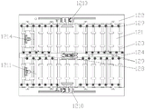
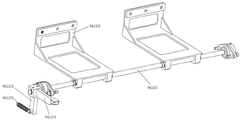
图2是本发明并联多通道传输装置的立体图。Fig. 2 is a perspective view of the parallel multi-channel transmission device of the present invention.
图3是图2的主视图。Fig. 3 is a front view of Fig. 2 .
图4是图2的俯视图。FIG. 4 is a top view of FIG. 2 .
图5是图2的左视图。Fig. 5 is a left side view of Fig. 2 .
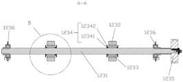
图6是本发明并联多通道传输装置中免调节积放辊的结构示意图。Fig. 6 is a schematic structural view of the adjustment-free accumulation rollers in the parallel multi-channel transmission device of the present invention.
图7是图6在A-A方向上的剖视图。Fig. 7 is a sectional view of Fig. 6 along the direction A-A.
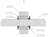
图8是图7中B处的放大结构示意图。FIG. 8 is a schematic diagram of an enlarged structure at B in FIG. 7 .
图9是本发明并联多通道传输装置中双向伞形阻挡机构的结构示意图。Fig. 9 is a schematic structural view of the bidirectional umbrella-shaped blocking mechanism in the parallel multi-channel transmission device of the present invention.
图10是图9的局部剖视图。FIG. 10 is a partial sectional view of FIG. 9 .
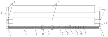
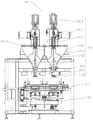
图11是本发明多通道大产能智能化外循环体系的结构示意图。Fig. 11 is a schematic structural diagram of a multi-channel, large-capacity intelligent external circulation system of the present invention.
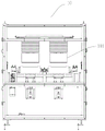
图12是本发明多通道大产能智能化外循环体系中多通道容器叠分装置的结构示意图。Fig. 12 is a structural schematic diagram of a multi-channel container stacking device in a multi-channel large-capacity intelligent external circulation system of the present invention.
图13是图12中联动组件的结构示意图。Fig. 13 is a schematic structural diagram of the linkage assembly in Fig. 12 .
图14是本发明多通道大产能智能化外循环体系中多通道粉料倒出装置的结构示意图。Fig. 14 is a structural schematic diagram of a multi-channel powder pouring device in a multi-channel large-capacity intelligent external circulation system of the present invention.
图15是图14去掉密封罩的结构示意图。Fig. 15 is a schematic structural view of Fig. 14 with the sealing cover removed.
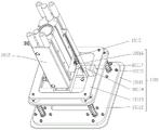
图16是图15中前挡件的结构示意图。Fig. 16 is a schematic structural view of the front stopper in Fig. 15 .
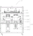
图17是本发明多通道大产能智能化外循环体系中多通道残余粉体检测装置的结构示意图。Fig. 17 is a schematic structural diagram of a multi-channel residual powder detection device in a multi-channel large-capacity intelligent external circulation system of the present invention.
图18是图17中检测组件的结构示意图。Fig. 18 is a schematic structural diagram of the detection component in Fig. 17 .
图19是本发明多通道大产能智能化外循环体系中多通道清扫装置的结构示意图。Fig. 19 is a structural schematic diagram of a multi-channel cleaning device in a multi-channel large-capacity intelligent external circulation system of the present invention.
图20是图19中清扫机构的结构示意图。Fig. 20 is a schematic structural view of the cleaning mechanism in Fig. 19 .
图21是本发明多通道大产能智能化外循环体系中多通道定量给料装置的结构示意图。Fig. 21 is a structural schematic diagram of a multi-channel quantitative feeding device in a multi-channel large-capacity intelligent external circulation system of the present invention.
图22是本发明多通道大产能智能化外循环体系中多通道粉料整平装置的结构示意图。Fig. 22 is a schematic structural view of the multi-channel powder leveling device in the multi-channel large-capacity intelligent external circulation system of the present invention.
图23是本发明多通道大产能智能化外循环体系中多通道切分装置的结构示意图。Fig. 23 is a schematic structural view of the multi-channel cutting device in the multi-channel large-capacity intelligent external circulation system of the present invention.
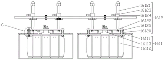
图24是图23中切刀装置的结构示意图。Fig. 24 is a schematic structural view of the cutter device in Fig. 23 .
图25是图24中C处的放大结构示意图。FIG. 25 is a schematic diagram of an enlarged structure at point C in FIG. 24 .
图中:In the picture:
1.传输处理线,1′.单通道传输线,1. Transmission processing line, 1′. Single channel transmission line,
11.支撑架,12.传输机构,121.底板,122.C型支架,123.免调节积放辊,124.分隔件,125.驱动件,126.传动组件,127 .“几”型支架,128.双向伞形阻挡机构,129.导向轮,1210.夹持件,1211.支撑轴,1212.支撑筋板,1213.可拆卸接料盒,1214.前阻挡件,11. Support frame, 12. Transmission mechanism, 121. Bottom plate, 122. C-shaped bracket, 123. Adjustment-free accumulating roller, 124. Divider, 125. Driving part, 126. Transmission component, 127. "Several" type bracket , 128. Two-way umbrella-shaped blocking mechanism, 129. Guide wheel, 1210. Clamping piece, 1211. Supporting shaft, 1212. Supporting rib plate, 1213. Removable receiving box, 1214. Front blocking piece,
1231.传动轴,1232.陶瓷辊,1233.非金属耐磨套,1234.限位件,1231. Transmission shaft, 1232. Ceramic roller, 1233. Non-metal wear-resistant sleeve, 1234. Limiting piece,
12341.轴挡圈,12342.O型挡圈,12311.安装槽,1235.传动齿轮,1236.连接件,1261.转轴,1262.驱动齿轮,1263.齿轮II,1264.齿轮I,1281.安装座,12811.安装孔,1282.驱动气缸,1283.主动连杆,1284.随动连杆组件,1285.阻挡组件,12851.挡板,12852.支撑框,12841.第一连杆,12842.第二连杆,12843.第三连杆,12844.连杆轴,12845.第四连杆,12846.连接轴,12847.第五连杆,128522.第二避让槽,12341. Shaft retaining ring, 12342. O-ring, 12311. Mounting groove, 1235. Transmission gear, 1236. Connector, 1261. Shaft, 1262. Driving gear, 1263. Gear II, 1264. Gear I, 1281. Installation Seat, 12811. Mounting hole, 1282. Driving cylinder, 1283. Active connecting rod, 1284. Follow-up connecting rod assembly, 1285. Blocking assembly, 12851. Baffle plate, 12852. Support frame, 12841. First connecting rod, 12842. The second connecting rod, 12843. The third connecting rod, 12844. The connecting rod shaft, 12845. The fourth connecting rod, 12846. The connecting shaft, 12847. The fifth connecting rod, 128522. The second escape groove,
2.处理炉,3.进炉移载机,4.出炉移载机,5.进料传输线,6.出料传输线, 8.升降机,17.多工位转角移载机,17′.单工位移载机,7′.单通道容器叠分装置,9′.单通道粉料倒出装置,10′.单通道残余粉体检测装置,13′.单通道清扫装置,14′.单通道定量给料装置,15′.单通道粉料整平装置,16′.单通道切分装置,2. Treatment furnace, 3. Furnace inlet transfer machine, 4. Furnace transfer machine, 5. Feed transmission line, 6. Discharge transmission line, 8. Elevator, 17. Multi-station corner transfer machine, 17′. Workplace loader, 7'. single-channel container stacking device, 9'. single-channel powder pouring device, 10'. single-channel residual powder detection device, 13'. single-channel cleaning device, 14'. single-channel Quantitative feeding device, 15'. Single channel powder leveling device, 16'. Single channel cutting device,
7.多通道容器叠分装置,71.顶升机构,74.夹持机构,741.夹持气缸,711.支架,712.联动组件,7121.第一气缸,7122.第一安装板,7123.同步升降器,7124.第二气缸,7125.第二安装板,7. Multi-channel container stacking device, 71. Jacking mechanism, 74. Clamping mechanism, 741. Clamping cylinder, 711. Bracket, 712. Linkage assembly, 7121. The first cylinder, 7122. The first mounting plate, 7123 .synchronous lifter, 7124. second cylinder, 7125. second mounting plate,
9.多通道粉料倒出装置,91.工作平台,92.密封罩,93.密封腔室,95.传输组件,96.翻转机构,951.第一减速电机,952.传输辊,961.限位组件,962.阻隔件,97.倒料斗,963.中心轴,964.转盘,965.锁紧盘,966.加固轴,9611.夹爪件,9612.前挡件,96121.阻挡轴,96122.阻挡板,96123.止动杆,96124.连杆,96125.复位弹簧,96126.连接块,96127.到位检测块,913.推力气缸,9. Multi-channel powder pouring device, 91. Working platform, 92. Sealing cover, 93. Sealing chamber, 95. Transmission component, 96. Turning mechanism, 951. First reduction motor, 952. Transmission roller, 961. Limiting assembly, 962. Barrier, 97. Ejecting hopper, 963. Central shaft, 964. Turntable, 965. Locking disc, 966. Reinforcement shaft, 9611. Jaw piece, 9612. Front stopper, 96121. Blocking shaft , 96122. blocking plate, 96123. stop rod, 96124. connecting rod, 96125. return spring, 96126. connection block, 96127. in-position detection block, 913. thrust cylinder,
10.多通道残余粉体检测装置,101.检测机构,1011.检测组件,1012.下推气缸,1013.传感器安装板,10111.检测板,10112.缓冲架,10113.安装板,10114.标尺,10115.标尺挡块,10116.光电传感器,10117.导块,10. Multi-channel residual powder detection device, 101. Detection mechanism, 1011. Detection component, 1012. Push down cylinder, 1013. Sensor mounting plate, 10111. Detection plate, 10112. Buffer frame, 10113. Mounting plate, 10114. Scale , 10115. Scale stopper, 10116. Photoelectric sensor, 10117. Guide block,
13.多通道清扫装置,131.清扫机构,132.上顶机构,1310.清扫单元,1311.固定基板,1312.Y轴导轨,1313.Y轴移动板,1314.X轴导轨,1315.X轴移动板,13101.驱动电机,13102.吸尘管,13103.转动轴,13104.毛刷头,1321.顶升台,1322.顶升气缸,1323.支撑座,1324.导杆,13. Multi-channel cleaning device, 131. Cleaning mechanism, 132. Lifting mechanism, 1310. Cleaning unit, 1311. Fixed base plate, 1312. Y-axis guide rail, 1313. Y-axis moving plate, 1314. X-axis guide rail, 1315.X Shaft moving plate, 13101. Drive motor, 13102. Dust suction pipe, 13103. Rotating shaft, 13104. Brush head, 1321. Jacking platform, 1322. Jacking cylinder, 1323. Support seat, 1324. Guide rod,
14.多通道定量给料装置,141.下料机构,142.XYZ运动机构,143.称重机构,1411.料仓,1412.螺旋出料杆,1413.第一驱动件,1414.第二驱动件,1415.搅拌件,1416.平推气缸,1417.连板,1418.翻盖板,1419.安装轴套,14111.竖直避让面,14. Multi-channel quantitative feeding device, 141. Unloading mechanism, 142. XYZ movement mechanism, 143. Weighing mechanism, 1411. Material bin, 1412. Spiral discharge rod, 1413. First driving part, 1414. Second Driving part, 1415. Agitator, 1416. Horizontal push cylinder, 1417. Connecting plate, 1418. Flip cover plate, 1419. Installing shaft sleeve, 14111. Vertical avoidance surface,
15.多通道粉料整平装置,151.并联搅拌机构,152.并联振动机构,1511.搅拌组件,1521.振动组件,1512.安装板I,15111.搅拌器,15112.搅拌器升降气缸,15113.吸尘罩,15114.吸尘罩升降气缸,15121.第一立板,15122.第二立板,15115.搅拌器安装座,15110.振动器,15116.吸尘罩安装座,1522.安装板II,15211.支撑台,15212.顶升移动板,15213.顶升气囊,15214.气动振动器,15. Multi-channel powder leveling device, 151. Parallel stirring mechanism, 152. Parallel vibration mechanism, 1511. Stirring assembly, 1521. Vibrating assembly, 1512. Mounting plate I, 15111. Agitator, 15112. Agitator lifting cylinder, 15113. Vacuum hood, 15114. Vacuum hood lifting cylinder, 15121. First vertical plate, 15122. Second vertical plate, 15115. Agitator mounting seat, 15110. Vibrator, 15116. Vacuum hood mounting seat, 1522. Mounting plate II, 15211. Support table, 15212. Lifting moving plate, 15213. Lifting air bag, 15214. Pneumatic vibrator,
16.多通道切分装置,161.并联切刀机构,162.举升机构,1611.切刀装置,1612.高度可调组件,16111.切刀安装板,16112.切刀,16113.振动器I,16121.安装轴,16122.高度调节板,16123.锁紧套,16124.万向把手,16125.螺栓,16120.缓冲组件,161201.上垫片,161202.弹簧,161203.下垫片。16. Multi-channel cutting device, 161. Parallel cutter mechanism, 162. Lifting mechanism, 1611. Cutter device, 1612. Height adjustable assembly, 16111. Cutter mounting plate, 16112. Cutter, 16113. Vibrator I, 16121. Installation shaft, 16122. Height adjustment plate, 16123. Lock sleeve, 16124. Universal handle, 16125. Bolt, 16120. Buffer assembly, 161201. Upper gasket, 161202. Spring, 161203. Lower gasket.
具体实施方式Detailed ways
现在结合附图和优选实施例对本发明作进一步的说明。这些附图均为简化的示意图,仅以示意方式说明本发明的基本结构,因此其仅显示与本发明有关的构成。The present invention will now be further described in conjunction with the accompanying drawings and preferred embodiments. These drawings are all simplified schematic diagrams, which only illustrate the basic structure of the present invention in a schematic manner, so they only show the configurations related to the present invention.
如图2~5所示,一种并联多通道传输装置,包括支撑架11和位于支撑架11上的传输机构12,传输机构12具有底板121、位于底板121两侧的C型支架122、免调节积放辊123、分隔件124、驱动件125和传动组件126,底板121固定在支撑架11顶部,免调节积放辊123的两端分别活动连接在两C型支架122上,C型支架122与底板121形成容置腔,任一C型支架122的容置腔内设有带动免调节积放辊123转动的传动组件126,传动组件126由安装在底板121上的驱动件125驱动,分隔件124设置在免调节积放辊123上,两者呈空间垂直关系,以形成并联的传输通道。As shown in Figures 2 to 5, a parallel multi-channel transmission device includes a
其中,底板121上固定有用于连接分隔件124的 “几”型支架127,分隔件124固定在“几”型支架127顶部,分隔件124上设有双向伞形阻挡机构128和导向轮129,导向轮129安装在分隔件124的两侧,C型支架122的顶部对应双向伞形阻挡机构128的位置上设置有夹持件1210,C型支架122的内侧壁对应导向轮129的位置也安装有导向轮129。 “几”型支架127上设有贯穿其前后与C型支架122连接的支撑轴1211,底板121上设有若干与支撑轴1211平行设置的支撑筋板1212。底板121上开设有通孔,通孔上安装有可拆卸接料盒1213。底板121上安装有前阻挡件1214和/或后阻挡件。Wherein, the
如图6所示,免调节积放辊123包括传动轴1231,传动轴1231上套设有若干陶瓷辊1232(一般为偶数个),陶瓷辊1232具有供传动轴1231穿过的穿过孔,该穿过孔与传动轴1231之间具有间隙,在间隙中设有非金属耐磨套1233,非金属耐磨套1233紧配合在陶瓷辊1232内壁上,且其与传动轴1231间隙配合,传动轴1231上靠近陶瓷辊1232两端面的位置处均设有一限位件1234。陶瓷辊1232的外周壁与物料接触,当陶瓷辊1232受物料重力时,陶瓷辊1232随传动轴1231转动;当陶瓷辊1232受到与移动方向相反的阻力时,传动轴1231转动,陶瓷辊1232停止转动,实现物品的积放。作为优选地,陶瓷辊1232和非金属耐磨套1233的两端面齐平;非金属耐磨套1233采用超高分子量聚乙烯。As shown in Figure 6, the adjustment-
如图7和图8所示,限位件1234包括轴挡圈12341和位于轴挡圈12341内侧的O型挡圈12342,传动轴1231上开设有安装轴挡圈12341的安装槽12311。轴挡圈12341的厚度大于安装槽12311的深度。优选地,O型挡圈12342采用金属材料。As shown in FIG. 7 and FIG. 8 , the limiting
如图6或图7所示,传动轴1231的一端安装有传动齿轮1235,在实施例中传动齿轮1235采用斜齿轮;传动轴1231上靠近动力传动齿轮1235处以及传动轴1231另一端处各设有与C型支架122连接的连接件1236。As shown in Fig. 6 or Fig. 7, one end of
陶瓷辊1232内置非金属耐磨套1233(材质为超高分子量聚乙烯)与传动轴1231摩擦,陶瓷辊1232受重时随传动轴1231转动;陶瓷辊1232输送方向受阻挡时,与传动轴1231脱离摩擦停止转动。非金属耐磨套1233与传动轴1231摩擦,只在陶瓷辊1232和传动轴1231之间实现积放,陶瓷辊1232与非金属耐磨套1233紧配成一体结构,前进方向受力时,物品和陶瓷辊1232之间摩擦力大于非金属耐磨套1233与传动轴1231的摩擦,陶瓷辊1232停止,传动轴1231依然转动。The
如图2所示,传动组件126包括转轴1261以及安装在转轴1261上的驱动齿轮1262和与传动齿轮1235啮合的齿轮II1263;驱动件125的输出端伸入容置腔内,且安装有与驱动齿轮1262啮合的齿轮I1264。在本实施例中,驱动齿轮1262、齿轮II1263和齿轮I1264均为斜齿轮。As shown in Figure 2, the
如图8和图9所示,双向伞形阻挡机构128包括安装座1281,安装座1281上设有若干安装孔12811,安装座1281中间沿其长度方向设置有驱动气缸1282,驱动气缸1282的推杆末端连接连杆机构,连杆机构包括一与推杆连接的主动连杆1283和两个随动连杆组件1284,两个随动连杆组件1284分别活动连接在主动连杆1283的两端,每个随动连杆组件1284活动连接一阻挡组件1285,阻挡组件1285与安装座1281活动连接。As shown in Figure 8 and Figure 9, the two-way umbrella-shaped
具体地,阻挡组件1285包括挡板12851,挡板12851的内壁上设有纵截面呈“]”的支撑框12852。随动连杆组件1284包括依次连接的第一连杆12841、第二连杆12842和第三连杆12843,第一连杆12841的一端与主动连杆1283的一端轴连接,第二连杆12842和第三连杆12843容置于支撑框12852的“]”开口内,第二连杆12842与第三连杆12843、第一连杆12841与第二连杆12842均通过连杆轴12844连接,且连杆轴12844均转动连接在支撑框12852上,具体是连杆轴12844贯穿支撑框12852的上下面。Specifically, the blocking
另外,第三连杆12843的一端通过连杆轴12844连接有第四连杆12845,第四连杆12845通过连接轴12846与安装座1281活动连接;第二连杆12842与第三连杆12843的连接轴12846上还连接有第五连杆12847,第五连杆12847通过连接轴12846与安装座1281活动连接。且,支撑框12852上对应第四连杆12845的处置设有当第四连杆12845转到与第三连杆12843的夹角最大时的第一避让槽128521。支撑框12852上对应第五连杆12847的处置设有当第五连杆12847转到与第三连杆12843的夹角最大时的第二避让槽128522。In addition, one end of the third connecting rod 12843 is connected to the fourth connecting rod 12845 through the connecting
作为优选地,驱动气缸1282的推杆通过浮动接头1286与主动连杆1283连接。且,主动连杆1283呈“工”字形结构,其两端具有容纳第一连杆12841端部的缺口12831。Preferably, the push rod of the
为了保证安装座1281的结构尽量小,故优选驱动气缸1282采用。本实施例的双向伞形阻挡采用连杆机构的死点原理,不容易反推(易推出不被反推):通过驱动气缸1282的推杆伸出,使得连杆机构的主动连杆1283向远离安装座1281发生位移,随动连杆组件1284跟随主动连杆1283联动,当第四连杆12845转到与第三连杆12843、第五连杆12847转到与第三连杆12843的夹角最大时,阻挡组件1285与安装座1281贴合,保证物料传输的通道宽度,通过驱动气缸1282的推杆缩回,使得连杆机构的主动连杆1283靠近安装座1281发生位移,随动连杆组件1284跟随主动连杆1283联动,当第四连杆12845转到与第三连杆12843、第五连杆12847转到与第三连杆12843的夹角为90°时,即为死点,靠此力挡住物料且不被反推,同时实现对两侧物料的挡齐,使得物料顺畅传输。In order to ensure that the structure of the mounting
为了保证各连杆与轴之间的动作的可靠稳定性,会增设自润滑轴承或非金属衬套;具体地,第一连杆12841、第二连杆12842与连杆轴12844之间设有自润滑轴承或非金属衬套,第三连杆12843与连杆轴12844之间设有自润滑轴承或非金属衬套;第二连杆12842、第三连杆12843、第五连杆12847与连杆轴12844之间设有自润滑轴承或非金属衬套,第五连杆12847与连接轴12846之间设有自润滑轴承或非金属衬套,第四连杆12845与连接轴12846之间设有自润滑轴承或非金属衬套,见图10中打剖面线处。In order to ensure the reliable stability of the action between each connecting rod and the shaft, self-lubricating bearings or non-metallic bushings will be added; specifically, between the first connecting
如图11所示,一种多通道大产能智能化外循环体系,包括处理炉2以及与处理炉2配合构成一循环的传输处理系统,传输处理系统包括分别与处理炉2进出口对接的进炉移载机3和出炉移载机4,以及进料传输线5、出料传输线6和传输处理线1,进料传输线5的一端设置进炉移载机3,其另一端与传输处理线1的一端对接,传输处理线1的另一端与出料传输线6的一端对接,出料传输线6的另一端设置出炉移载机4,传输处理线1包括若干上述方案中的并联多通道传输装置以及若干处理装置,这些处理装置包括依次设置的多通道容器叠分装置7(设置在前面是起到分离容器的作用)、升降机8、多通道粉料倒出装置9、多通道残余粉体检测装置10、多通道清扫装置13、多通道定量给料装置14、多通道粉料整平装置15、多通道切分装置16和多通道容器叠分装置7(设置在后面是起到叠合容器的作用),其中,多通道容器叠分装置7、多通道残余粉体检测装置10、多通道清扫装置13、多通道定量给料装置14、多通道粉料整平装置15和多通道切分装置16内部均具有与并联多通道传输装置的传输机构12相同的并联传输机构。另外,还包括自动控制传输处理系统运行的可视化控制系统(图中未示出),传输处理线1的两端分别设有与进料传输线5和出料传输线6对接的多工位转角移载机17。As shown in Figure 11, a multi-channel large-capacity intelligent external circulation system includes a
本实施例中传输处理线1上的并联多通道传输装置和若干处理装置均以双通道(双工位)为例来说明。In this embodiment, the parallel multi-channel transmission device and several processing devices on the
如图12所示,多通道容器叠分装置7包括顶升机构71、并联传输机构和夹持机构74,夹持机构74包括若干纵向分布的夹持气缸741,并联传输机构具有若干传输通道,顶升机构71包括与传输通道数量相同的支架711及同时顶升所有支架711的联动组件712。As shown in Figure 12, the multi-channel
如图13所示,联动组件712包括第一气缸7121、第一安装板7122、同步升降器7123、第二气缸7124和第二安装板7125,第一气缸7121安装在装置框架的底板上,其推杆穿过第一安装板7122,第一安装板7122边沿设置有同步升降器7123,第二气缸7124固定在第二安装板7125上,其推杆与第一气缸7121的推杆相连,第一气缸7121的行程大于第二气缸7124的行程。As shown in Figure 13, the
由并联传输机构同时传输过来的两个容器被前阻挡件1214阻挡到位后,第一气缸7121的推杆伸出,将容器顶升到到位置A,位于上层的夹持气缸741的推杆推出插入容器底部托住容器,避免夹持气缸741的力太大而夹碎容器,第一气缸7121的推杆收回;由并联传输机构同时传输过来的另两个容器被前阻挡件1214阻挡到位后,第二气缸7124的推杆伸出,将容器顶升到到位置B,位于下层的夹持气缸741的推杆推出,将容器定位,此时上层容器置于下层容器之上;位于上层的夹持气缸741的推杆收回,第二气缸7124的推杆收回,一个传输通道上的上、下两个容器回落到并联传输机构上,从而实现叠合(分离就是将动作倒过来再走一遍),上述动作都是两列容器同时运动。After the two containers transported by the parallel transmission mechanism are blocked in place by the
如图14所示,多通道粉料倒出装置9包括工作平台91和安装在工作平台91上的密封罩92,密封罩92和工作平台91之间形成密封腔室93,密封腔室93内工作平台91上设有容器的传输组件95和翻转机构96,传输组件95包括第一减速电机951、传动组件(齿轮传动机构)和若干传输辊952,第一减速电机951安装在工作平台91上,传动组件设置在翻转机构96一端,传输辊952并排安装在翻转机构96上,翻转机构96上设有翻转时限位容器的限位组件961以及将传输辊952分成两个传输通道的一个阻隔件962,工作平台91下设有倒料斗97。As shown in Figure 14 , the multi-channel powder
如图15所示,去掉密封罩92的结构示意图,翻转机构96包括第二减速电机(图中未显示,为现有技术)、中心轴963、安装在中心轴963两端的转盘964以及分布在中心轴963中间的阻隔件962,阻隔件962的截面呈大割圆形状,阻隔件962上开设有供传输辊952穿过的槽口9621,中心轴963与阻隔件962及转盘964通过锁紧盘965连接,两个转盘964分别与阻隔件962用三根加固轴966连接,保证转盘964与阻隔件962不会松开。As shown in Figure 15, remove the schematic diagram of the structure of the sealing
限位组件961包括夹爪件9611和前挡件9612,夹爪件9611安装在转盘964内侧上部以及阻隔件962的上端两侧,如图16所示,前挡件9612包括安装在两转盘964上的阻挡轴96121,阻挡轴96121上设有两个阻挡板96122,阻挡板96122呈L型结构,阻挡轴96121的一端安装有止动杆96123和连杆96124,连杆96124与止动杆96123呈直角,止动杆96123的下端连接复位弹簧96125的一端,复位弹簧96125的另一端通过连接块96126连接在转盘964上,止动杆96123一侧的转盘964上设有到位检测块96127。连杆96124的一端与阻挡轴96121活动连接,其另一端为自由端,该自由端下方的工作平台91上设有推力气缸913。The
两个容器输送至密封腔室93内,由前挡件9612阻挡停下,翻转机构96翻转180°,夹爪件9611挡住容器,将容器中的粉料倒出,到位检测块96127检测到容器翻转到位后,反向翻转回到初始位置;倒料结束后,推力气缸913推出活塞杆,推动连杆96124使得阻挡轴96121转动,带动阻挡板96122跟随转动,使得阻挡板96122全部位于传输辊952下方,传输组件95将空的容器输送出去,前挡件9612通过复位弹簧96125自动归位。The two containers are transported into the sealed
如图17和图18所示,多通道残余粉体检测装置10包括检测机构101和并联传输机构,检测机构101设置有两个,每个检测机构101包括检测组件1011和驱动检测组件1011下降并伸入容器内的下推气缸1012,检测组件1011包括检测板10111、缓冲架10112、安装板10113、标尺10114、标尺挡块10115、光电传感器10116和导块10117,检测板10111固定在缓冲架10112底部,安装板10113连接在缓冲架10112顶部,安装板10113上开设有供下推气缸1012伸出端穿过的通孔,下推气缸1012伸出端连接至缓冲架10112的顶面,标尺挡块10115设置在安装板10113一端边沿上,标尺10114固定在缓冲架10112的顶面,且与标尺挡块10115配合,下推气缸1012的一侧壁底部连接有传感器安装板1013,传感器安装板1013的顶面固定有光电传感器10116,光电传感器安装板1013的底面上固定导块10117,导块10117贴近标尺10114表面。As shown in Figures 17 and 18, the multi-channel residual
两个容器传输至检测位,并联传输机构将容器定位,上方两个检测机构101同时下降(气缸伸出,标尺10114会随着气缸一起下降)伸入容器,光电传感器10116会检测标尺10114的位置,如果容器内有残余物料,光电传感器10116检测到标尺10114触发报警,之后检测机构101回升,检测完成。The two containers are transported to the detection position, the parallel transmission mechanism positions the container, and the upper two
如图19和图20所示所示,多通道清扫装置13包括清扫机构131、并联传输机构和上顶机构132,清扫机构131具有若干并排设置的清扫单元1310,清扫机构131包括固定基板1311,固定基板1311上安装有Y轴导轨1312, Y轴导轨1312上设有沿其来回移动的Y轴移动板1313, Y轴移动板1313上开设有与清扫单元1310数量相同的安装孔,安装孔两边的Y轴移动板1313上固定有X轴导轨1314,X轴导轨1314上设有沿其来回移动的X轴移动板1315, X轴移动板1315上并排安装有若干清扫单元1310;清扫单元1310包括驱动电机13101、传动机构、四个毛刷组件和吸尘管13102,驱动电机13101安装在X轴移动板1315一侧边沿,四个毛刷组件围绕吸尘管13102设置,且吸尘管13102紧抵毛刷组件,毛刷组件包括转动轴13103和安装在转动轴13103上的毛刷头13104,传动机构包括主动轮、从动轮和同步带,主动轮安装在驱动电机13101的输出端上,从动轮安装在转动轴13103的上端,且与主动轮通过同步带连接;并联传输机构具有与清扫单元1310数量相同的传输通道,上顶机构132包括与传输通道数量一致的上顶组件,上顶组件包括顶升台1321、顶升气缸1322和支撑座1323,顶升台1321位于并联传输机构上方,支撑座1323位于并联传输机构下方,并联传输机构上设有导套,顶升台1321与支撑座1323之间设有导杆1324,支撑座1323上连接顶升气缸1322,顶升气缸1322的推杆端部连接顶升台1321。As shown in Figures 19 and 20, the
上顶组件同时将容器顶起到一定高度,并联限位机构限位容器,清扫单元1310从中间位置出发,在上位机的控制下行“回”字形轨迹,毛刷组件贴合容器内壁,四个毛刷头13104同时旋转清扫,配合中间吸尘管13102,边扫边吸,轨迹终止回到中间位置;上顶升组件下降,容器回落到并联限位机构上。The upper top assembly lifts the container up to a certain height at the same time, and the parallel limit mechanism limits the container. The
如图21所示,多通道定量给料装置14包括若干下料机构141、并联传输机构、XYZ运动机构142和称重机构143,并联传输机构位于下料机构141的下方,具有与下料机构141数量相同的传输通道,XYZ运动机构142连接于并联传输机构下方,称重机构143并排连接在XYZ运动机构142的顶部,称重机构143的上部穿过并联传输机构支撑并举升容器,下料机构141包括料仓1411、螺旋出料杆1412、第一驱动件1413、第二驱动件1414、搅拌件1415、平推气缸1416、连板1417和翻盖板1418,相邻下料机构141的料仓1411上部具有竖直避让面14111,料仓1411顶部设有进料口,其底部设有出料口,第一驱动件1413的输出端连接螺旋出料杆1412,螺旋出料杆1412的下端贯穿料仓1411底部,第二驱动件1414的输出端设置有主动锥齿轮,螺旋出料杆1412外设有安装轴套1419,安装轴套1419的顶部固定有与主动锥齿轮啮合的从动锥齿轮,安装轴套1419的下部连接有搅拌件1415,平推气缸1416的输出端连接倾斜设置的连板1417,连板1417的下端连接覆盖在出料口上的翻盖板1418。As shown in Figure 21, the multi-channel
容器在运行到阻挡处时先后停下,称重机构143将并联传输机构顶起,下料机构141同时下料,通过位于容器下方的称重机构143测得重量之后,在XYZ运动机构142带动下行“回”字型轨迹,完成下料之后称重机构143和并联传输机构下降。The container stops successively when it runs to the blocking position, the weighing
如图22所示,多通道粉料整平装置15包括并联搅拌机构151、并联传输机构和并联振动机构152,并联搅拌机构151包括至少两个并排设置的搅拌组件1511,并联传输机构具有与搅拌组件1511数量相同的传输通道,并联振动机构152具有与传输通道数量相同的振动组件1521,搅拌组件1511通过安装板I1512安装于装置框架上部,搅拌组件1511包括搅拌器15111、搅拌器升降气缸15112、吸尘罩15113和吸尘罩升降气缸15114,安装板I1512上相对设置有第一立板15121和第二立板15122,第一立板15121上安装有搅拌器升降气缸15112,搅拌器升降气缸15112的推杆末端连接搅拌器安装座15115,搅拌器安装座15115上安装有振动器15110,第二立板15122上安装有吸尘罩升降气缸15114,吸尘罩升降气缸15114的推杆末端连接吸尘罩安装座15116,振动组件1521通过安装板II1522安装于装置框架下部,振动组件1521包括支撑台15211、顶升移动板15212、顶升气囊15213和气动振动器15214,支撑台15211通过支撑杆连接在顶升移动板15212上,支撑台15211下方安装有气动振动器15214,顶升移动板15212下方安装有顶升气囊15213。As shown in Figure 22, the multi-channel
容器传输到位,顶升气囊15213将整个并联振动机构152顶离并联传输机构,上方两吸尘罩15113同时降下到与容器上边沿保持一定距离,搅拌器15111降下伸入容器内物料中均匀搅拌,搅拌结束后搅拌器15111收回,搅拌器安装座15115上的振动器15110进行振动,将搅拌器15111上带着的物料抖落于容器中;下方振动组件1521的两个气动振动器15214分别对两个容器支撑台15211进行振动,此时容器内的物料被快速振平,扬起的细微粉尘通过上方吸尘罩15113集中除尘;气动振动器15214的频率和振幅可调,可适应不同特性的物料,满足不同客户需求,最后顶升气囊15213下降,容器落回并联传输机构上,往下一个工位输送。The container is transported in place, the jacking
如图23所示,所述多通道切分装置16包括并联切刀机构161、并联传输机构和举升机构162,并联切刀机构161包括并排设置的若干切刀装置1611,切刀装置1611设有高度可调组件1612;并联传输机构设置于并联切刀机构161的下方,其具有与切刀装置1611数量相同的输送通道,举升机构162设置于并联传输机构上,其具有与输送通道数量相同的顶升组件(该顶升组件与多通道清扫装置13的上顶组件结构相同),如图24所示,切刀装置1611通过固定板安装在装置框架上部,切刀装置1611包括切刀安装板16111和切刀16112,切刀16112连接在切刀安装板16111上,切刀安装板16111通过高度可调组件1612与固定板连接,切刀安装板16111上设置有振动器I16113。As shown in Figure 23, described
其中,高度可调组件1612包括安装轴16121和高度调节板16122,安装轴16121竖直穿过固定板与高度调节板16122连接,安装轴16121上具有一扁槽,安装轴16121外套设有锁紧套16123,锁紧套16123上设有贯穿锁紧套16123锁紧安装轴16121的万向把手16124,高度调节板16122与切刀安装板16111之间具有一定距离,且两者通过螺栓16125连接,螺栓16125上设有缓冲组件16120。Wherein, the height
如图25所示,缓冲组件16120包括套设在螺栓16125上的上垫片161201、弹簧161202和下垫片161203,上垫片161201和下垫片161203分别贴合高度调节板16122底面和切刀安装板16111顶面设置,弹簧161202设置在上垫片161201和下垫片161203之间,上垫片161201和下垫片161203为非金属垫。As shown in Figure 25, the
下方两个上顶升组件同时将容器顶起到一定高度,切刀16112插入容器内的物料,将物料均匀切分为5X5的格子(也可以根据需要切分成其他数量的格子,只要更换不同规格的切刀),之后容器下降到并联传输机构上,振动器I16113振动抖落切刀16112上残留的物料,上顶升组件降下,容器落到并联传输机构上,即可输送到下个工位。The two upper lifting components below lift the container to a certain height at the same time, the
多通道大产能智能化外循环体系的工艺流程为:配混料系统出来的原材料装入容器中→对容器中的物料进行整平→对整平后的物料进行切分→容器叠放→输送进入处理炉2烧制→出炉→叠放的容器分离→将成品料从容器中倒出送入粉碎输送系统→空容器残余粉体检测→空容器完成清扫→进入新一轮生产循环。The process flow of the multi-channel large-capacity intelligent external circulation system is as follows: the raw materials from the compounding system are loaded into the container → the material in the container is leveled → the leveled material is divided → the container is stacked → conveyed Enter into the
本实施例的多通道大产能智能化外循环体系将产能由传统的90~150钵/时提高到300~500钵/时,产能提高3~4倍,可视化控制系统具备手动操作、自动运行、设备运行状态监视、故障报警、历史数据记录、可视化管理等功能;同时,提高了生产加工过程中的关键技术水平:装料精度达到±50g以内,摇匀后容器内料位高度差≤5mm(常规大于10mm),容器高度适应80~220mm(一般180mm以内),双工位配置保证并列容器同时同步工作,保证锂离子电极材料加工质量,满足新能源行业对锂电池生产的需求。The multi-channel large-capacity intelligent external circulation system of this embodiment increases the production capacity from the traditional 90-150 bowls/hour to 300-500 bowls/hour, and the production capacity is increased by 3-4 times. The visual control system has manual operation, automatic operation, Equipment operation status monitoring, fault alarm, historical data recording, visual management and other functions; at the same time, the key technical level in the production and processing process has been improved: the charging accuracy is within ±50g, and the height difference of the material level in the container after shaking is ≤5mm ( Usually greater than 10mm), the height of the container is 80-220mm (generally within 180mm), and the dual-station configuration ensures that parallel containers work simultaneously and simultaneously, ensuring the processing quality of lithium-ion electrode materials, and meeting the needs of the new energy industry for lithium battery production.
上述实施例只为说明本发明的技术构思及特点,其目的在于让熟悉此项技术的人士能够了解本发明的内容并加以实施,并不能以此限制本发明的保护范围,凡根据本发明精神实质所作的等效变化或修饰,都应涵盖在本发明的保护范围内。The above-mentioned embodiments are only to illustrate the technical conception and characteristics of the present invention. Substantial equivalent changes or modifications shall fall within the protection scope of the present invention.
Claims (22)
Priority Applications (1)
| Application Number | Priority Date | Filing Date | Title |
|---|---|---|---|
| CN202211243895.2A CN115321087B (en) | 2022-10-12 | 2022-10-12 | Parallel multi-channel transmission device and multi-channel high-capacity intelligent external circulation system |
Applications Claiming Priority (1)
| Application Number | Priority Date | Filing Date | Title |
|---|---|---|---|
| CN202211243895.2A CN115321087B (en) | 2022-10-12 | 2022-10-12 | Parallel multi-channel transmission device and multi-channel high-capacity intelligent external circulation system |
Publications (2)
| Publication Number | Publication Date |
|---|---|
| CN115321087A true CN115321087A (en) | 2022-11-11 |
| CN115321087B CN115321087B (en) | 2023-03-24 |
Family
ID=83915015
Family Applications (1)
| Application Number | Title | Priority Date | Filing Date |
|---|---|---|---|
| CN202211243895.2A Active CN115321087B (en) | 2022-10-12 | 2022-10-12 | Parallel multi-channel transmission device and multi-channel high-capacity intelligent external circulation system |
Country Status (1)
| Country | Link |
|---|---|
| CN (1) | CN115321087B (en) |
Cited By (1)
| Publication number | Priority date | Publication date | Assignee | Title |
|---|---|---|---|---|
| CN117163677A (en) * | 2023-11-03 | 2023-12-05 | 泰州圣斯泰科汽车部件有限公司 | A storage device for automobile instrument processing |
Citations (5)
| Publication number | Priority date | Publication date | Assignee | Title |
|---|---|---|---|---|
| CN103512368A (en) * | 2013-10-14 | 2014-01-15 | 苏州汇科机电设备有限公司 | Automatic sagger discharging device used in electronic powder material production line |
| CN108123100A (en) * | 2018-01-17 | 2018-06-05 | 广东中鹏热能科技有限公司 | A kind of lithium electric material full-automatic production method and production line |
| CN211569207U (en) * | 2019-12-25 | 2020-09-25 | 成都鸿信木业有限公司 | Double translation roller platform |
| CN214421468U (en) * | 2020-12-30 | 2021-10-19 | 常州百韩科智能装备有限公司 | Conveniently adjust sealed transfer chain that damping freely opened and shut |
| CN216004023U (en) * | 2021-09-28 | 2022-03-11 | 龙工(福建)铸锻有限公司 | Feeding and discharging device of automatic hub machining line |
-
2022
- 2022-10-12 CN CN202211243895.2A patent/CN115321087B/en active Active
Patent Citations (5)
| Publication number | Priority date | Publication date | Assignee | Title |
|---|---|---|---|---|
| CN103512368A (en) * | 2013-10-14 | 2014-01-15 | 苏州汇科机电设备有限公司 | Automatic sagger discharging device used in electronic powder material production line |
| CN108123100A (en) * | 2018-01-17 | 2018-06-05 | 广东中鹏热能科技有限公司 | A kind of lithium electric material full-automatic production method and production line |
| CN211569207U (en) * | 2019-12-25 | 2020-09-25 | 成都鸿信木业有限公司 | Double translation roller platform |
| CN214421468U (en) * | 2020-12-30 | 2021-10-19 | 常州百韩科智能装备有限公司 | Conveniently adjust sealed transfer chain that damping freely opened and shut |
| CN216004023U (en) * | 2021-09-28 | 2022-03-11 | 龙工(福建)铸锻有限公司 | Feeding and discharging device of automatic hub machining line |
Cited By (2)
| Publication number | Priority date | Publication date | Assignee | Title |
|---|---|---|---|---|
| CN117163677A (en) * | 2023-11-03 | 2023-12-05 | 泰州圣斯泰科汽车部件有限公司 | A storage device for automobile instrument processing |
| CN117163677B (en) * | 2023-11-03 | 2024-02-23 | 泰州圣斯泰科汽车部件有限公司 | A storage device for automobile instrument processing |
Also Published As
| Publication number | Publication date |
|---|---|
| CN115321087B (en) | 2023-03-24 |
Similar Documents
| Publication | Publication Date | Title |
|---|---|---|
| CN216533718U (en) | Agricultural product cleaning device | |
| CN111994400B (en) | Ton bag automatic unpacking, unloading and recycling device and working method | |
| CN115321087B (en) | Parallel multi-channel transmission device and multi-channel high-capacity intelligent external circulation system | |
| CN114644210B (en) | Stacking equipment for processing bagged cement | |
| CN116553208B (en) | Limestone exploitation and unloading equipment and unloading method thereof | |
| CN216444587U (en) | A kind of container floor assembly production and conveying equipment | |
| CN212923147U (en) | Closed air locking type plate type feeding machine with quick-release door structure | |
| CN212330634U (en) | Automatic polishing system for nails | |
| CN203951895U (en) | Microcomputerized control sack filling machine | |
| CN111590438A (en) | Automatic polishing system for nails | |
| CN213168123U (en) | A raw material handling and feeding device | |
| CN222203563U (en) | Grain receiving bucket structure of grain processing equipment | |
| CN223521921U (en) | A ship's hold unloading device | |
| CN220906212U (en) | T-shaped elevator | |
| CN219838802U (en) | Wrapping bag collection device for ink jet numbering machine | |
| CN219278666U (en) | Broken bale bulk cargo collection device of fodder conveyer belt | |
| CN223508617U (en) | Automatic boxing device of station of boxing packagine machine | |
| CN222248748U (en) | A coal cleaning device for the tail of a scraper conveyor | |
| CN220055355U (en) | A multi-layer lifting type battery sheet collecting box | |
| CN223421546U (en) | A fully automatic material transfer device | |
| CN222630433U (en) | Stepped rotary feeding and discharging device | |
| CN223175295U (en) | Feeding device suitable for chemical raw materials coated in material bag | |
| CN222224500U (en) | Betel nut feeding device | |
| CN222790912U (en) | A pipe cutting device | |
| CN222409675U (en) | Rotary parts feeding device |
Legal Events
| Date | Code | Title | Description |
|---|---|---|---|
| PB01 | Publication | ||
| PB01 | Publication | ||
| SE01 | Entry into force of request for substantive examination | ||
| SE01 | Entry into force of request for substantive examination | ||
| GR01 | Patent grant | ||
| GR01 | Patent grant | ||
| CP03 | Change of name, title or address |
Address after: 213000 Jiangsu Province Changzhou City Xitaihu Science and Technology Industrial Park Tenglong Road No. 2 Building No. 9 Patentee after: Yangshi Intelligent Equipment (Changzhou) Co., Ltd. Country or region after: China Address before: 213149 Jiangsu Province, Changzhou City, Xitaihu Science and Technology Industrial Park, No. 2 Tenglong Road Patentee before: Changzhou baihanke Intelligent Equipment Co.,Ltd. Country or region before: China |
|
| CP03 | Change of name, title or address |