CN115316100A - High-efficient ecological agriculture is with accurate fertilizer injection unit in farmland - Google Patents
High-efficient ecological agriculture is with accurate fertilizer injection unit in farmland Download PDFInfo
- Publication number
- CN115316100A CN115316100A CN202210616555.3A CN202210616555A CN115316100A CN 115316100 A CN115316100 A CN 115316100A CN 202210616555 A CN202210616555 A CN 202210616555A CN 115316100 A CN115316100 A CN 115316100A
- Authority
- CN
- China
- Prior art keywords
- stirring
- wall
- farmland
- water tank
- driving
- Prior art date
- Legal status (The legal status is an assumption and is not a legal conclusion. Google has not performed a legal analysis and makes no representation as to the accuracy of the status listed.)
- Granted
Links
Images




Classifications
-
- A—HUMAN NECESSITIES
- A01—AGRICULTURE; FORESTRY; ANIMAL HUSBANDRY; HUNTING; TRAPPING; FISHING
- A01C—PLANTING; SOWING; FERTILISING
- A01C23/00—Distributing devices specially adapted for liquid manure or other fertilising liquid, including ammonia, e.g. transport tanks or sprinkling wagons
- A01C23/04—Distributing under pressure; Distributing mud; Adaptation of watering systems for fertilising-liquids
-
- A—HUMAN NECESSITIES
- A01—AGRICULTURE; FORESTRY; ANIMAL HUSBANDRY; HUNTING; TRAPPING; FISHING
- A01G—HORTICULTURE; CULTIVATION OF VEGETABLES, FLOWERS, RICE, FRUIT, VINES, HOPS OR SEAWEED; FORESTRY; WATERING
- A01G25/00—Watering gardens, fields, sports grounds or the like
- A01G25/02—Watering arrangements located above the soil which make use of perforated pipe-lines or pipe-lines with dispensing fittings, e.g. for drip irrigation
-
- B—PERFORMING OPERATIONS; TRANSPORTING
- B05—SPRAYING OR ATOMISING IN GENERAL; APPLYING FLUENT MATERIALS TO SURFACES, IN GENERAL
- B05B—SPRAYING APPARATUS; ATOMISING APPARATUS; NOZZLES
- B05B1/00—Nozzles, spray heads or other outlets, with or without auxiliary devices such as valves, heating means
- B05B1/28—Nozzles, spray heads or other outlets, with or without auxiliary devices such as valves, heating means with integral means for shielding the discharged liquid or other fluent material, e.g. to limit area of spray; with integral means for catching drips or collecting surplus liquid or other fluent material
-
- B—PERFORMING OPERATIONS; TRANSPORTING
- B05—SPRAYING OR ATOMISING IN GENERAL; APPLYING FLUENT MATERIALS TO SURFACES, IN GENERAL
- B05B—SPRAYING APPARATUS; ATOMISING APPARATUS; NOZZLES
- B05B15/00—Details of spraying plant or spraying apparatus not otherwise provided for; Accessories
- B05B15/20—Arrangements for agitating the material to be sprayed, e.g. for stirring, mixing or homogenising
- B05B15/25—Arrangements for agitating the material to be sprayed, e.g. for stirring, mixing or homogenising using moving elements, e.g. rotating blades
-
- B—PERFORMING OPERATIONS; TRANSPORTING
- B05—SPRAYING OR ATOMISING IN GENERAL; APPLYING FLUENT MATERIALS TO SURFACES, IN GENERAL
- B05B—SPRAYING APPARATUS; ATOMISING APPARATUS; NOZZLES
- B05B15/00—Details of spraying plant or spraying apparatus not otherwise provided for; Accessories
- B05B15/50—Arrangements for cleaning; Arrangements for preventing deposits, drying-out or blockage; Arrangements for detecting improper discharge caused by the presence of foreign matter
-
- B—PERFORMING OPERATIONS; TRANSPORTING
- B05—SPRAYING OR ATOMISING IN GENERAL; APPLYING FLUENT MATERIALS TO SURFACES, IN GENERAL
- B05B—SPRAYING APPARATUS; ATOMISING APPARATUS; NOZZLES
- B05B9/00—Spraying apparatus for discharge of liquids or other fluent material, without essentially mixing with gas or vapour
- B05B9/03—Spraying apparatus for discharge of liquids or other fluent material, without essentially mixing with gas or vapour characterised by means for supplying liquid or other fluent material
- B05B9/04—Spraying apparatus for discharge of liquids or other fluent material, without essentially mixing with gas or vapour characterised by means for supplying liquid or other fluent material with pressurised or compressible container; with pump
- B05B9/0403—Spraying apparatus for discharge of liquids or other fluent material, without essentially mixing with gas or vapour characterised by means for supplying liquid or other fluent material with pressurised or compressible container; with pump with pumps for liquids or other fluent material
-
- Y—GENERAL TAGGING OF NEW TECHNOLOGICAL DEVELOPMENTS; GENERAL TAGGING OF CROSS-SECTIONAL TECHNOLOGIES SPANNING OVER SEVERAL SECTIONS OF THE IPC; TECHNICAL SUBJECTS COVERED BY FORMER USPC CROSS-REFERENCE ART COLLECTIONS [XRACs] AND DIGESTS
- Y02—TECHNOLOGIES OR APPLICATIONS FOR MITIGATION OR ADAPTATION AGAINST CLIMATE CHANGE
- Y02A—TECHNOLOGIES FOR ADAPTATION TO CLIMATE CHANGE
- Y02A40/00—Adaptation technologies in agriculture, forestry, livestock or agroalimentary production
- Y02A40/10—Adaptation technologies in agriculture, forestry, livestock or agroalimentary production in agriculture
Landscapes
- Life Sciences & Earth Sciences (AREA)
- Soil Sciences (AREA)
- Engineering & Computer Science (AREA)
- Water Supply & Treatment (AREA)
- Environmental Sciences (AREA)
- Fertilizing (AREA)
Abstract
本发明公开了一种高效生态农业用农田精准施肥装置,包括水箱,所述水箱的内部设置有水泵,所述水箱的外壁插设有输出管,所述输出管的一端与水泵的输出端相连,所述输出管分布于农田,所述水箱的外表面设置有控制器,所述水泵与控制器采用电性连接,包括搅拌机构、喷洒机构、驱动机构和辅助机构,搅拌机构,所述搅拌机构用于搅拌肥料,所述搅拌机构设置在水箱内;利用驱动机构启动辅助机构,驱动机构将喷洒机构喷洒出的部分肥料挡住,落入到辅助机构内,辅助机构再将收集到肥料撒入到喷洒机构附近的农田,保证喷洒机构附近的农田撒满足够的肥料,全程不使用化石燃料,使用电能,清洁环保,并且碳排放较少。

The invention discloses a farmland precision fertilization device for efficient ecological agriculture, comprising a water tank, a water pump is arranged inside the water tank, an output pipe is inserted into the outer wall of the water tank, and one end of the output pipe is connected with the output end of the water pump , the output pipe is distributed in the farmland, the outer surface of the water tank is provided with a controller, and the water pump and the controller are electrically connected, including a stirring mechanism, a spraying mechanism, a driving mechanism and an auxiliary mechanism, a stirring mechanism, and the stirring mechanism. The mechanism is used for stirring fertilizer, and the stirring mechanism is arranged in the water tank; the auxiliary mechanism is activated by the driving mechanism, and the driving mechanism blocks part of the fertilizer sprayed by the spraying mechanism and falls into the auxiliary mechanism, and the auxiliary mechanism then spreads the collected fertilizer into the To the farmland near the spraying institution, ensure that the farmland near the spraying institution is covered with enough fertilizer, and the whole process does not use fossil fuels, uses electricity, is clean and environmentally friendly, and has less carbon emissions.
Description
技术领域technical field
本发明涉及农业装置。The present invention relates to agricultural equipment.
背景技术Background technique
农业,是利用动植物的生长发育规律,通过人工培育来获得产品的产业。农业属于第一产业,研究农业的科学是农学。Agriculture is an industry that uses the growth and development laws of animals and plants to obtain products through artificial cultivation. Agriculture belongs to the primary industry, and the science that studies agriculture is agronomy.
农业的劳动对象是有生命的动植物,获得的产品是动植物本身。农业是提供支撑国民经济建设与发展的基础产业。The objects of labor in agriculture are living animals and plants, and the products obtained are the animals and plants themselves. Agriculture is the basic industry that provides support for the construction and development of the national economy.
现如今的农业施肥,一般是使用肥料车或者人工施肥,而两种施肥的速度较差,较为费时费力,并且不够方便,需要人员在整个田地上来回跑动,而且使用肥料车在移动施肥的过程中,会对农作物压损或者压坏,使农作物的收成降低一部分。Today's agricultural fertilization generally uses fertilizer trucks or manual fertilization, and the speed of the two types of fertilization is poor, time-consuming and labor-intensive, and not convenient enough. It requires personnel to run back and forth across the field, and fertilizer trucks are used in mobile fertilization. In the process, the crops will be damaged or crushed, and the harvest of the crops will be reduced by a part.
发明内容Contents of the invention
本发明的目的在于克服现有常规的施肥速度慢的缺陷而提供的一种高效生态农业用农田精准施肥装置。The object of the present invention is to provide a high-efficiency ecological agriculture precision fertilization device for overcoming the defect of slow fertilization speed in the existing conventional methods.
实现上述目的的技术方案是:一种高效生态农业用农田精准施肥装置,包括水箱,所述水箱的内部设置有水泵,所述水箱的外壁插设有输出管,所述输出管的一端与水泵的输出端相连,所述输出管分布于农田,所述水箱的外表面设置有控制器,所述水泵与控制器采用电性连接,包括搅拌机构、喷洒机构、驱动机构和辅助机构;The technical solution to achieve the above purpose is: a farmland precision fertilization device for high-efficiency ecological agriculture, including a water tank, a water pump is arranged inside the water tank, an output pipe is inserted into the outer wall of the water tank, and one end of the output pipe is connected to the water pump. The output pipes are connected to each other, the output pipes are distributed in the farmland, the outer surface of the water tank is provided with a controller, and the water pump is electrically connected to the controller, including a stirring mechanism, a spraying mechanism, a driving mechanism and an auxiliary mechanism;
搅拌机构,所述搅拌机构用于搅拌肥料,所述搅拌机构设置在水箱内;A stirring mechanism, the stirring mechanism is used to stir the fertilizer, and the stirring mechanism is arranged in the water tank;
喷洒机构,所述喷洒机构用于喷洒肥料,所述喷洒机构设置在输出管上;a spraying mechanism, the spraying mechanism is used for spraying fertilizer, and the spraying mechanism is arranged on the output pipe;
驱动机构,所述驱动机构用于驱动辅助机构,所述驱动机构设置在喷洒机构上;a driving mechanism, the driving mechanism is used to drive the auxiliary mechanism, and the driving mechanism is arranged on the spraying mechanism;
辅助机构,所述辅助机构用于提高喷洒机构的喷洒效果,所述辅助机构设置在驱动机构上。The auxiliary mechanism is used to improve the spraying effect of the spraying mechanism, and the auxiliary mechanism is arranged on the driving mechanism.
优选的,所述搅拌机构包括搅拌电机、转轴、搅拌杆、转环和搅拌叶,所述水箱的顶端设置有搅拌电机,所述搅拌电机的输出端连接有转轴,所述转轴的外壁连接有多个搅拌杆,所述搅拌杆的外壁转动连接有转环,所述转环的外壁连接有多个搅拌叶,所述搅拌电机与控制器采用电性连接。Preferably, the stirring mechanism includes a stirring motor, a rotating shaft, a stirring rod, a swivel and stirring blades, a stirring motor is arranged on the top of the water tank, a rotating shaft is connected to the output end of the stirring motor, and the outer wall of the rotating shaft is connected to A plurality of stirring rods, the outer wall of the stirring rod is rotatably connected with a swivel ring, the outer wall of the swivel ring is connected with a plurality of stirring blades, and the stirring motor is electrically connected with the controller.
优选的,所述喷洒机构包括导管和喷头,所述导管的底端与输出管连接,所述导管的内部与输出管连通,所述导管的上端连接有喷头。Preferably, the spraying mechanism includes a conduit and a spray head, the bottom end of the conduit is connected to the output pipe, the inside of the conduit communicates with the output pipe, and the upper end of the conduit is connected to the spray head.
优选的,所述驱动机构包括底盘、推杆电机、伸缩杆、封盖、导杆、连杆、驱动齿条、驱动齿轮、圆轴、支撑杆、驱动锥齿轮和圆孔,所述导管的外壁连接有底盘,所述底盘的外壁开设有多个圆孔,所述底盘的上端连接有推杆电机,所述推杆电机与控制器采用电性连接,所述推杆电机的输出端连接有伸缩杆,所述伸缩杆的顶端连接有封盖,所述封盖位于喷头的正上方,所述底盘的顶端连接有导杆,所述导杆的外壁贯穿封盖,所述封盖的直径大于喷头的直径;Preferably, the drive mechanism includes a chassis, a push rod motor, a telescopic rod, a cover, a guide rod, a connecting rod, a drive rack, a drive gear, a circular shaft, a support rod, a drive bevel gear and a circular hole. The outer wall is connected with a chassis, the outer wall of the chassis is provided with a plurality of round holes, the upper end of the chassis is connected with a push rod motor, the push rod motor is electrically connected with the controller, and the output end of the push rod motor is connected to There is a telescopic rod, the top of the telescopic rod is connected with a cover, the cover is located directly above the nozzle, the top of the chassis is connected with a guide rod, the outer wall of the guide rod runs through the cover, and the cover The diameter is greater than the diameter of the nozzle;
所述伸缩杆的外壁连接有连杆,所述连杆远离伸缩杆连接有驱动齿条,所述底盘的上端连接有支撑杆,所述支撑杆的外壁转动连接有圆轴,所述圆轴的一端连接有驱动齿轮,所述圆轴的另一端连接有驱动锥齿轮,所述驱动齿轮与驱动齿条啮合。The outer wall of the telescopic rod is connected with a connecting rod, and the connecting rod is connected with a driving rack away from the telescopic rod, and the upper end of the chassis is connected with a support rod, and the outer wall of the support rod is rotatably connected with a circular shaft, and the circular shaft One end of the circular shaft is connected with a driving gear, and the other end of the circular shaft is connected with a driving bevel gear, and the driving gear meshes with the driving rack.
优选的,所述辅助机构包括转向锥齿轮、连轴、驱动轮、皮带、从动轮、接收盘和通孔,所述底盘的上端转动连接有连轴,所述连轴的外壁连接有驱动轮,所述连轴的顶端连接有转向锥齿轮,所述转向锥齿轮与驱动锥齿轮啮合,所述驱动轮的外壁活动连接有皮带,所述导管的外壁活动连接有接收盘,所述接收盘的底端连接有从动轮,所述从动轮的外壁与皮带活动连接,所述接收盘的外壁开设有多个通孔,所述接收盘的形状为圆台状,所述接收盘的顶端直接大于喷头的直径。Preferably, the auxiliary mechanism includes a steering bevel gear, a connecting shaft, a driving wheel, a belt, a driven wheel, a receiving plate and a through hole, the upper end of the chassis is connected to a connecting shaft in rotation, and the outer wall of the connecting shaft is connected to a driving wheel , the top of the connecting shaft is connected with a steering bevel gear, the steering bevel gear meshes with the driving bevel gear, the outer wall of the driving wheel is movably connected with a belt, the outer wall of the conduit is movably connected with a receiving plate, and the receiving plate A driven wheel is connected to the bottom end of the driven wheel, and the outer wall of the driven wheel is movably connected with the belt. The outer wall of the receiving tray is provided with a plurality of through holes. The shape of the receiving tray is a circular truncated shape. The diameter of the sprinkler.
优选的,所述水箱的上端设置有进水管,所述水箱的上表面设置有进料管。Preferably, the upper end of the water tank is provided with a water inlet pipe, and the upper surface of the water tank is provided with a feed pipe.
优选的,所述输出管的末端设置有电磁阀,所述电磁阀与控制器采用电性连接。Preferably, a solenoid valve is provided at the end of the output pipe, and the solenoid valve is electrically connected to the controller.
优选的,所述推杆电机、伸缩杆的、封盖、导杆和连杆均套设有光滑薄膜。Preferably, the push rod motor, the telescopic rod, the cover, the guide rod and the connecting rod are all covered with a smooth film.
本发明的有益效果是:The beneficial effects of the present invention are:
1、将水和肥料分别通过进水管和进料管输入到水箱内,利用控制器,启动搅拌机构,将水箱内的肥料搅拌均匀,然后,再启动水泵,水泵将肥料溶液抽入到输出管内,从而进入到喷洒机构内,喷洒机构将肥料撒入到农田内,利用驱动机构启动辅助机构,驱动机构将喷洒机构喷洒出的部分肥料挡住,落入到辅助机构内,辅助机构再将收集到肥料撒入到喷洒机构附近的农田,保证喷洒机构附近的农田撒满足够的肥料。1. Input water and fertilizer into the water tank through the water inlet pipe and the feed pipe respectively, use the controller to start the stirring mechanism, and stir the fertilizer in the water tank evenly, then start the water pump, and the water pump will pump the fertilizer solution into the output pipe , so as to enter the spraying mechanism, the spraying mechanism sprinkles the fertilizer into the farmland, uses the driving mechanism to start the auxiliary mechanism, the driving mechanism blocks part of the fertilizer sprayed by the spraying mechanism, falls into the auxiliary mechanism, and the auxiliary mechanism collects the fertilizer The fertilizer is sprinkled into the farmland near the spraying mechanism to ensure that the farmland near the spraying mechanism is covered with enough fertilizer.
2、驱动机构将喷洒机构封闭,对水箱内充满水,利用水泵将水推入到输出管和喷洒机构内,来将输出管和喷洒机构进行冲刷,然后,打开电磁阀,将输出管内水排出,避免水箱内残留过多的肥料溶液,从而使装置可以洒水,实现了施肥和洒水两用的效果,全程不使用化石燃料,使用电能,清洁环保,并且碳排放较少。2. The driving mechanism closes the spraying mechanism, fills the water tank with water, uses the water pump to push the water into the output pipe and the spraying mechanism to wash the output pipe and the spraying mechanism, and then opens the solenoid valve to discharge the water in the output pipe , to avoid too much fertilizer solution remaining in the water tank, so that the device can be sprinkled, realizing the effect of fertilization and watering, the whole process does not use fossil fuels, uses electric energy, clean and environmentally friendly, and has less carbon emissions.
3、驱动锥齿轮带动转向锥齿轮转动,转向锥齿轮带动连轴转动,连轴带动驱动轮转动,驱动轮带动皮带移动,皮带带动从动轮转动,从动轮带动接收盘转动,而喷头喷出的部分溶液被封盖挡住,落到接收盘内,接收盘将溶液从通孔甩出,利用接收盘的形状为倒立圆台状,使通孔的朝向朝下,从而使甩出的肥料溶液落在喷头附近的农田,来避免喷头不易喷洒到附近农田的缺陷发生。3. The driving bevel gear drives the steering bevel gear to rotate. The steering bevel gear drives the shaft to rotate. Part of the solution is blocked by the cover and falls into the receiving tray. The receiving tray throws the solution out of the through hole. The shape of the receiving tray is an inverted circular truncated shape, so that the direction of the through hole is downward, so that the thrown fertilizer solution falls on the The farmland near the nozzle to avoid the defect that the nozzle is not easy to spray to the nearby farmland.
附图说明Description of drawings
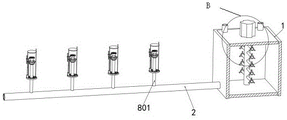
图1是本发明的前视结构示意图;Fig. 1 is the front view structural representation of the present invention;
图2是本发明的剖面结构示意图;Fig. 2 is the sectional structure schematic diagram of the present invention;
图3是本发明的俯视结构示意图;Fig. 3 is a top view structural representation of the present invention;
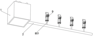
图4是本发明的仰视结构示意图;Fig. 4 is the bottom view structure schematic diagram of the present invention;
图5是图1中A处的放大结构示意图;Fig. 5 is a schematic diagram of an enlarged structure at A in Fig. 1;
图6是图2中B处的放大结构示意图;Fig. 6 is a schematic diagram of an enlarged structure at B in Fig. 2;
图7是图3中C处的放大结构示意图;Fig. 7 is a schematic diagram of an enlarged structure at C in Fig. 3;
图8是图4中D处的放大结构示意图。FIG. 8 is a schematic diagram of an enlarged structure at D in FIG. 4 .
1、水箱;2、输出管;3、电磁阀;4、控制器;5、进水管;6、进料管;7、搅拌机构;701、搅拌电机;702、转轴;703、搅拌杆;704、转环;705、搅拌叶;8、喷洒机构;801、导管;802、喷头;9、驱动机构;901、底盘;902、推杆电机;903、伸缩杆;904、封盖;905、导杆;906、连杆;907、驱动齿条;908、驱动齿轮;909、圆轴;910、支撑杆;911、驱动锥齿轮;912、圆孔;10、辅助机构;1001、转向锥齿轮;1002、连轴;1003、驱动轮;1004、皮带;1005、从动轮;1006、接收盘;1007、通孔。1. Water tank; 2. Output pipe; 3. Solenoid valve; 4. Controller; 5. Inlet pipe; 6. Feed pipe; 7. Stirring mechanism; 701. Stirring motor; 702. Rotating shaft; 703. Stirring rod; 704 , swivel; 705, stirring blade; 8, spraying mechanism; 801, conduit; 802, nozzle; 9, driving mechanism; 901, chassis; 902, push rod motor; 903, telescopic rod; Rod; 906, connecting rod; 907, driving rack; 908, driving gear; 909, circular shaft; 910, support rod; 911, driving bevel gear; 912, circular hole; 10, auxiliary mechanism; 1001, steering bevel gear; 1002, connecting shaft; 1003, driving wheel; 1004, belt; 1005, driven wheel; 1006, receiving plate; 1007, through hole.
具体实施方式Detailed ways
下面将结合附图对本发明的技术方案进行清楚、完整地描述。在本发明的描述中,需要说明的是,术语“中心”、“上”、“下”、“左”、“右”、“竖直”、“水平”、“内”、“外”等指示的方位或位置关系为基于附图所示的方位或位置关系,仅是为了便于描述本发明和简化描述,而不是指示或暗示所指的装置或元件必须具有特定的方位、以特定的方位构造和操作,因此不能理解为对本发明的限制。此外,术语“第一”、“第二”、“第三”仅用于描述目的,而不能理解为指示或暗示相正对地重要性。The technical solutions of the present invention will be clearly and completely described below in conjunction with the accompanying drawings. In the description of the present invention, it should be noted that the terms "center", "upper", "lower", "left", "right", "vertical", "horizontal", "inner", "outer" etc. The indicated orientation or positional relationship is based on the orientation or positional relationship shown in the drawings, and is only for the convenience of describing the present invention and simplifying the description, rather than indicating or implying that the referred device or element must have a specific orientation, or in a specific orientation. construction and operation, therefore, should not be construed as limiting the invention. In addition, the terms "first", "second", and "third" are used for descriptive purposes only, and should not be construed as indicating or implying relative importance.
下面将结合附图对本发明作进一步说明。The present invention will be further described below in conjunction with accompanying drawing.
参考附图1-8,一种高效生态农业用农田精准施肥装置,包括水箱1,水箱1的内部设置有水泵,水箱1的外壁插设有输出管2,输出管2的一端与水泵的输出端相连,输出管2分布于农田,水箱1的外表面设置有控制器4,水泵与控制器4采用电性连接,水箱1的上端设置有进水管5,水箱1的上表面设置有进料管6,输出管2的末端设置有电磁阀3,电磁阀3与控制器4采用电性连接,包括搅拌机构7、喷洒机构8、驱动机构9和辅助机构10;Referring to accompanying drawings 1-8, a farmland precision fertilization device for high-efficiency ecological agriculture includes a water tank 1. A water pump is arranged inside the water tank 1. An
搅拌机构7,搅拌机构7用于搅拌肥料,搅拌机构7设置在水箱1内;A stirring mechanism 7, the stirring mechanism 7 is used to stir the fertilizer, and the stirring mechanism 7 is arranged in the water tank 1;
喷洒机构8,喷洒机构8用于喷洒肥料,喷洒机构8设置在输出管2上;A
驱动机构9,驱动机构9用于驱动辅助机构10,驱动机构9设置在喷洒机构8上;A
辅助机构10,辅助机构10用于提高喷洒机构8的喷洒效果,辅助机构10设置在驱动机构9上。The
将水和肥料分别通过进水管5和进料管6输入到水箱1内,利用控制器4,启动搅拌机构7,将水箱1内的肥料搅拌均匀,然后,再启动水泵,水泵将肥料溶液抽入到输出管2内,从而进入到喷洒机构8内,喷洒机构8将肥料撒入到农田内,利用驱动机构9启动辅助机构10,驱动机构9将喷洒机构8喷洒出的部分肥料挡住,落入到辅助机构10内,辅助机构10再将收集到肥料撒入到喷洒机构8附近的农田,保证喷洒机构8附近的农田撒满足够的肥料,待肥料撒完后,驱动机构9将喷洒机构8封闭,对水箱1内充满水,利用水泵将水推入到输出管2和喷洒机构8内,来将输出管2和喷洒机构8进行冲刷,然后,打开电磁阀3,将输出管2内水排出,避免水箱1内残留过多的肥料溶液,从而使装置可以洒水,实现了施肥和洒水两用的效果,全程不使用化石燃料,使用电能,清洁环保,并且碳排放较少。Input water and fertilizer into the water tank 1 through the
参考附图1-6,搅拌机构7包括搅拌电机701、转轴702、搅拌杆703、转环704和搅拌叶705,水箱1的顶端设置有搅拌电机701,搅拌电机701的输出端连接有转轴702,转轴702的外壁连接有多个搅拌杆703,搅拌杆703的外壁转动连接有转环704,转环704的外壁连接有多个搅拌叶705,搅拌电机701与控制器4采用电性连接,搅拌电机701型号为YBX4。With reference to accompanying drawing 1-6, stirring mechanism 7 comprises stirring
控制器4启动搅拌电机701,搅拌电机701带动转轴702转动,转轴702带动搅拌杆703转动,搅拌杆703搅拌水箱1内的肥料,搅拌杆703带动转环704转动,转环704会由于水的阻力自身转动,使转环704带动搅拌叶705转动,提高了肥料搅拌的效果。
参考附图1-5,喷洒机构8包括导管801和喷头802,导管801的底端与输出管2连接,导管801的内部与输出管2连通,导管801的上端连接有喷头802。With reference to accompanying drawing 1-5,
输出管2将溶液输送到导管801内,导管801再通过喷头802将肥料溶液喷洒到农田内。The
参考附图1-8,驱动机构9包括底盘901、推杆电机902、伸缩杆903、封盖904、导杆905、连杆906、驱动齿条907、驱动齿轮908、圆轴909、支撑杆910、驱动锥齿轮911和圆孔912,导管801的外壁连接有底盘901,底盘901的外壁开设有多个圆孔912,底盘901的上端连接有推杆电机902,推杆电机902的型号为 LA14,推杆电机902与控制器4采用电性连接,推杆电机902的输出端连接有伸缩杆903,伸缩杆903的顶端连接有封盖904,封盖904位于喷头802的正上方,底盘901的顶端连接有导杆905,导杆905的外壁贯穿封盖904,封盖904的直径大于喷头802的直径;With reference to accompanying drawing 1-8,
伸缩杆903的外壁连接有连杆906,连杆906远离伸缩杆903连接有驱动齿条907,底盘901的上端连接有支撑杆910,支撑杆910的外壁转动连接有圆轴909,圆轴909的一端连接有驱动齿轮908,圆轴909的另一端连接有驱动锥齿轮911,驱动齿轮908与驱动齿条907啮合。The outer wall of the
控制器4启动推杆电机902运行,推杆电机902带动伸缩杆903往复移动,伸缩杆903带动封盖904移动,封盖904与喷头802的距离循环调节,使喷头802喷出的部分溶液被封盖904挡住,落到辅助机构10内,在需要冲刷喷头802时,封盖904会移动到喷头802的顶端,将喷头802堵住,使水可以冲刷喷头802的内部,同时,水不会从喷头802喷出;The
伸缩杆903带动连杆906往复移动,连杆906带动驱动齿条907往复移动,驱动齿条907带动驱动齿轮908往复转动,驱动齿轮908带动圆轴909往复转动,圆轴909带动驱动锥齿轮911转动,圆孔912是避免肥料溶液堆积在底盘901上。The
参考附图1-8,辅助机构10包括转向锥齿轮1001、连轴1002、驱动轮1003、皮带1004、从动轮1005、接收盘1006和通孔1007,底盘901的上端转动连接有连轴1002,连轴1002的外壁连接有驱动轮1003,连轴1002的顶端连接有转向锥齿轮1001,转向锥齿轮1001与驱动锥齿轮911啮合,驱动轮1003的外壁活动连接有皮带1004,导管801的外壁活动连接有接收盘1006,接收盘1006的底端连接有从动轮1005,从动轮1005的外壁与皮带1004活动连接,接收盘1006的外壁开设有多个通孔1007,接收盘1006的形状为圆台状,接收盘1006的顶端直接大于喷头802的直径。With reference to accompanying drawing 1-8,
驱动锥齿轮911带动转向锥齿轮1001转动,转向锥齿轮1001带动连轴1002转动,连轴1002带动驱动轮1003转动,驱动轮1003带动皮带1004移动,皮带1004带动从动轮1005转动,从动轮1005带动接收盘1006转动,而喷头802喷出的部分溶液被封盖904挡住,落到接收盘1006内,接收盘1006将溶液从通孔1007甩出,利用接收盘1006的形状为倒立圆台状,使通孔1007的朝向朝下,从而使甩出的肥料溶液落在喷头802附近的农田,来避免喷头802不易喷洒到附近农田的缺陷发生。The driving
参考附图1-8,推杆电机902、伸缩杆903的、封盖904、导杆905和连杆906均套设有光滑薄膜,使肥料溶液不易粘附在推杆电机902、伸缩杆903的、封盖904、导杆905和连杆906上。With reference to accompanying drawing 1-8, push
以上各实施例仅用以说明本发明的技术方案,而非对其限制;尽管参照前述各实施例对本发明进行了详细的说明,本领域的普通技术人员应当理解:其依然可以对前述各实施例所记载的技术方案进行修改,或者对其中部分或者全部技术特征进行等同替换;而这些修改或者替换,并不使相应技术方案的本质脱离本发明各实施例技术方案的范围。The above embodiments are only used to illustrate the technical solutions of the present invention, and are not intended to limit them; although the present invention has been described in detail with reference to the foregoing embodiments, those of ordinary skill in the art should understand that: it can still be applied to the foregoing embodiments The technical solutions described in the examples are modified, or some or all of the technical features are equivalently replaced; and these modifications or replacements do not make the essence of the corresponding technical solutions depart from the scope of the technical solutions of the embodiments of the present invention.
Claims (8)
Priority Applications (1)
| Application Number | Priority Date | Filing Date | Title |
|---|---|---|---|
| CN202210616555.3A CN115316100B (en) | 2022-06-01 | 2022-06-01 | A high-efficiency ecological agriculture farmland precision fertilization device |
Applications Claiming Priority (1)
| Application Number | Priority Date | Filing Date | Title |
|---|---|---|---|
| CN202210616555.3A CN115316100B (en) | 2022-06-01 | 2022-06-01 | A high-efficiency ecological agriculture farmland precision fertilization device |
Publications (2)
| Publication Number | Publication Date |
|---|---|
| CN115316100A true CN115316100A (en) | 2022-11-11 |
| CN115316100B CN115316100B (en) | 2023-07-14 |
Family
ID=83915840
Family Applications (1)
| Application Number | Title | Priority Date | Filing Date |
|---|---|---|---|
| CN202210616555.3A Active CN115316100B (en) | 2022-06-01 | 2022-06-01 | A high-efficiency ecological agriculture farmland precision fertilization device |
Country Status (1)
| Country | Link |
|---|---|
| CN (1) | CN115316100B (en) |
Cited By (1)
| Publication number | Priority date | Publication date | Assignee | Title |
|---|---|---|---|---|
| CN116849250A (en) * | 2023-07-06 | 2023-10-10 | 江西省林业科学院 | Non-damage fresh-keeping equipment and method based on bamboo shoots |
Citations (7)
| Publication number | Priority date | Publication date | Assignee | Title |
|---|---|---|---|---|
| US20040084552A1 (en) * | 2002-10-31 | 2004-05-06 | Huartson Warren Craig | Lawn and garden sprayer |
| CN109348812A (en) * | 2018-10-09 | 2019-02-19 | 马鞍山沐及信息科技有限公司 | A kind of nursery stock fertilizer apparatus and method |
| CN110839512A (en) * | 2019-11-26 | 2020-02-28 | 东北林业大学 | Multi-functional nursery automatic watering device |
| CN212544609U (en) * | 2020-06-15 | 2021-02-19 | 海南东潭沙农业开发有限公司 | Sweet potato is planted and is sprayed fertilizer injection unit with mixing |
| CN215012265U (en) * | 2021-04-25 | 2021-12-07 | 山西水务工程项目管理有限公司 | Water-saving drip irrigation system for greening of colleges and universities |
| CN216362582U (en) * | 2021-09-09 | 2022-04-26 | 福州市峇斌新材料推广研发有限公司 | Fertilizer sprinkler is used in agricultural |
| WO2022094954A1 (en) * | 2020-11-06 | 2022-05-12 | 唐山圣因海洋科技有限公司 | Water saving apparatus for use in agricultural apparatus, and method for water saving apparatus |
-
2022
- 2022-06-01 CN CN202210616555.3A patent/CN115316100B/en active Active
Patent Citations (7)
| Publication number | Priority date | Publication date | Assignee | Title |
|---|---|---|---|---|
| US20040084552A1 (en) * | 2002-10-31 | 2004-05-06 | Huartson Warren Craig | Lawn and garden sprayer |
| CN109348812A (en) * | 2018-10-09 | 2019-02-19 | 马鞍山沐及信息科技有限公司 | A kind of nursery stock fertilizer apparatus and method |
| CN110839512A (en) * | 2019-11-26 | 2020-02-28 | 东北林业大学 | Multi-functional nursery automatic watering device |
| CN212544609U (en) * | 2020-06-15 | 2021-02-19 | 海南东潭沙农业开发有限公司 | Sweet potato is planted and is sprayed fertilizer injection unit with mixing |
| WO2022094954A1 (en) * | 2020-11-06 | 2022-05-12 | 唐山圣因海洋科技有限公司 | Water saving apparatus for use in agricultural apparatus, and method for water saving apparatus |
| CN215012265U (en) * | 2021-04-25 | 2021-12-07 | 山西水务工程项目管理有限公司 | Water-saving drip irrigation system for greening of colleges and universities |
| CN216362582U (en) * | 2021-09-09 | 2022-04-26 | 福州市峇斌新材料推广研发有限公司 | Fertilizer sprinkler is used in agricultural |
Non-Patent Citations (1)
| Title |
|---|
| 朱新国等: "宁波市多元化灌溉施肥技术应用与实践", 节水灌溉, no. 5, pages 64 - 66 * |
Cited By (2)
| Publication number | Priority date | Publication date | Assignee | Title |
|---|---|---|---|---|
| CN116849250A (en) * | 2023-07-06 | 2023-10-10 | 江西省林业科学院 | Non-damage fresh-keeping equipment and method based on bamboo shoots |
| CN116849250B (en) * | 2023-07-06 | 2025-01-21 | 江西省林业科学院 | A kind of device and method based on non-injury preservation of bamboo shoots |
Also Published As
| Publication number | Publication date |
|---|---|
| CN115316100B (en) | 2023-07-14 |
Similar Documents
| Publication | Publication Date | Title |
|---|---|---|
| CN112753560B (en) | Soilless culture device for ecological agriculture | |
| CN111418328A (en) | Gardens irrigation equipment convenient to water conservation | |
| CN206165592U (en) | Drive formula pesticide spray truck | |
| CN108293969A (en) | A kind of small-size multifunction pesticide-spraying cart | |
| CN115316100B (en) | A high-efficiency ecological agriculture farmland precision fertilization device | |
| CN110999664A (en) | a seedling system | |
| CN209609190U (en) | A kind of field foliage spray device | |
| CN219514632U (en) | Fertilizer for agricultural land planting | |
| CN118370070A (en) | Agricultural sprinkler irrigation and fertilization integrated machine and use method thereof | |
| CN219019550U (en) | Fertilizing and spraying machine | |
| CN218941751U (en) | Automatic water and fertilizer integrated machine for agricultural planting | |
| CN216452433U (en) | Afforestation sprinkler for municipal works | |
| CN117546711A (en) | An integrated water and fertilizer irrigation and fertilization device for agricultural smart greenhouses | |
| CN117099554A (en) | Automatic pesticide fertilizer spraying device for seedling-raising forests | |
| CN214800793U (en) | Water, fertilizer and pesticide integrated sprinkling irrigation device for agriculture | |
| CN210782069U (en) | Frequency conversion pressurization atomizer for tea garden | |
| CN210928626U (en) | Irrigation equipment for fruit tree cultivation | |
| CN211430747U (en) | Horticulture is with green cultivation of planting with spouting medicine device | |
| CN220493833U (en) | Agricultural energy-saving mechanical irrigation mechanism | |
| CN222283967U (en) | Spraying device for fertilizing in forest seed orchard | |
| CN220733895U (en) | Agricultural fertilizer injection unit | |
| CN218897515U (en) | Afforestation is with removing fertilizer injection unit | |
| CN221634421U (en) | Agricultural irrigation fertilizer injection unit | |
| CN217905138U (en) | Fertilizer injection unit for ecological agriculture | |
| CN206923284U (en) | Integrally drop sprays dual-purpose Irrigation Machine to a kind of liquid manure |
Legal Events
| Date | Code | Title | Description |
|---|---|---|---|
| PB01 | Publication | ||
| PB01 | Publication | ||
| SE01 | Entry into force of request for substantive examination | ||
| SE01 | Entry into force of request for substantive examination | ||
| GR01 | Patent grant | ||
| GR01 | Patent grant |