CN115303098A - Oil-immersed mute charging pile for new energy automobile - Google Patents
Oil-immersed mute charging pile for new energy automobile Download PDFInfo
- Publication number
- CN115303098A CN115303098A CN202211031228.8A CN202211031228A CN115303098A CN 115303098 A CN115303098 A CN 115303098A CN 202211031228 A CN202211031228 A CN 202211031228A CN 115303098 A CN115303098 A CN 115303098A
- Authority
- CN
- China
- Prior art keywords
- oil
- thermostat
- heat exchange
- charging pile
- module
- Prior art date
- Legal status (The legal status is an assumption and is not a legal conclusion. Google has not performed a legal analysis and makes no representation as to the accuracy of the status listed.)
- Withdrawn
Links
- 238000001816 cooling Methods 0.000 claims abstract description 81
- 230000017525 heat dissipation Effects 0.000 claims abstract description 55
- 239000007788 liquid Substances 0.000 claims description 7
- 238000010586 diagram Methods 0.000 description 11
- 239000003570 air Substances 0.000 description 8
- 239000000428 dust Substances 0.000 description 5
- 239000012080 ambient air Substances 0.000 description 3
- 230000000694 effects Effects 0.000 description 3
- 230000020169 heat generation Effects 0.000 description 3
- 238000009825 accumulation Methods 0.000 description 2
- 238000005516 engineering process Methods 0.000 description 2
- 239000012535 impurity Substances 0.000 description 2
- 238000000034 method Methods 0.000 description 2
- 238000012986 modification Methods 0.000 description 2
- 230000004048 modification Effects 0.000 description 2
- XLYOFNOQVPJJNP-UHFFFAOYSA-N water Chemical compound O XLYOFNOQVPJJNP-UHFFFAOYSA-N 0.000 description 2
- 230000009286 beneficial effect Effects 0.000 description 1
- 230000008602 contraction Effects 0.000 description 1
- 239000002826 coolant Substances 0.000 description 1
- 238000005260 corrosion Methods 0.000 description 1
- 230000007797 corrosion Effects 0.000 description 1
- 125000004122 cyclic group Chemical group 0.000 description 1
- 238000011161 development Methods 0.000 description 1
- 238000001914 filtration Methods 0.000 description 1
- 239000007789 gas Substances 0.000 description 1
- 238000010438 heat treatment Methods 0.000 description 1
- 238000009434 installation Methods 0.000 description 1
- 239000011229 interlayer Substances 0.000 description 1
- 230000007774 longterm Effects 0.000 description 1
- 238000012423 maintenance Methods 0.000 description 1
- 239000002184 metal Substances 0.000 description 1
- 238000012544 monitoring process Methods 0.000 description 1
- 238000007789 sealing Methods 0.000 description 1
- 239000002699 waste material Substances 0.000 description 1
Images


Classifications
-
- B—PERFORMING OPERATIONS; TRANSPORTING
- B60—VEHICLES IN GENERAL
- B60L—PROPULSION OF ELECTRICALLY-PROPELLED VEHICLES; SUPPLYING ELECTRIC POWER FOR AUXILIARY EQUIPMENT OF ELECTRICALLY-PROPELLED VEHICLES; ELECTRODYNAMIC BRAKE SYSTEMS FOR VEHICLES IN GENERAL; MAGNETIC SUSPENSION OR LEVITATION FOR VEHICLES; MONITORING OPERATING VARIABLES OF ELECTRICALLY-PROPELLED VEHICLES; ELECTRIC SAFETY DEVICES FOR ELECTRICALLY-PROPELLED VEHICLES
- B60L53/00—Methods of charging batteries, specially adapted for electric vehicles; Charging stations or on-board charging equipment therefor; Exchange of energy storage elements in electric vehicles
- B60L53/30—Constructional details of charging stations
- B60L53/31—Charging columns specially adapted for electric vehicles
-
- B—PERFORMING OPERATIONS; TRANSPORTING
- B60—VEHICLES IN GENERAL
- B60L—PROPULSION OF ELECTRICALLY-PROPELLED VEHICLES; SUPPLYING ELECTRIC POWER FOR AUXILIARY EQUIPMENT OF ELECTRICALLY-PROPELLED VEHICLES; ELECTRODYNAMIC BRAKE SYSTEMS FOR VEHICLES IN GENERAL; MAGNETIC SUSPENSION OR LEVITATION FOR VEHICLES; MONITORING OPERATING VARIABLES OF ELECTRICALLY-PROPELLED VEHICLES; ELECTRIC SAFETY DEVICES FOR ELECTRICALLY-PROPELLED VEHICLES
- B60L53/00—Methods of charging batteries, specially adapted for electric vehicles; Charging stations or on-board charging equipment therefor; Exchange of energy storage elements in electric vehicles
- B60L53/30—Constructional details of charging stations
- B60L53/302—Cooling of charging equipment
-
- Y—GENERAL TAGGING OF NEW TECHNOLOGICAL DEVELOPMENTS; GENERAL TAGGING OF CROSS-SECTIONAL TECHNOLOGIES SPANNING OVER SEVERAL SECTIONS OF THE IPC; TECHNICAL SUBJECTS COVERED BY FORMER USPC CROSS-REFERENCE ART COLLECTIONS [XRACs] AND DIGESTS
- Y02—TECHNOLOGIES OR APPLICATIONS FOR MITIGATION OR ADAPTATION AGAINST CLIMATE CHANGE
- Y02T—CLIMATE CHANGE MITIGATION TECHNOLOGIES RELATED TO TRANSPORTATION
- Y02T10/00—Road transport of goods or passengers
- Y02T10/60—Other road transportation technologies with climate change mitigation effect
- Y02T10/70—Energy storage systems for electromobility, e.g. batteries
-
- Y—GENERAL TAGGING OF NEW TECHNOLOGICAL DEVELOPMENTS; GENERAL TAGGING OF CROSS-SECTIONAL TECHNOLOGIES SPANNING OVER SEVERAL SECTIONS OF THE IPC; TECHNICAL SUBJECTS COVERED BY FORMER USPC CROSS-REFERENCE ART COLLECTIONS [XRACs] AND DIGESTS
- Y02—TECHNOLOGIES OR APPLICATIONS FOR MITIGATION OR ADAPTATION AGAINST CLIMATE CHANGE
- Y02T—CLIMATE CHANGE MITIGATION TECHNOLOGIES RELATED TO TRANSPORTATION
- Y02T10/00—Road transport of goods or passengers
- Y02T10/60—Other road transportation technologies with climate change mitigation effect
- Y02T10/7072—Electromobility specific charging systems or methods for batteries, ultracapacitors, supercapacitors or double-layer capacitors
-
- Y—GENERAL TAGGING OF NEW TECHNOLOGICAL DEVELOPMENTS; GENERAL TAGGING OF CROSS-SECTIONAL TECHNOLOGIES SPANNING OVER SEVERAL SECTIONS OF THE IPC; TECHNICAL SUBJECTS COVERED BY FORMER USPC CROSS-REFERENCE ART COLLECTIONS [XRACs] AND DIGESTS
- Y02—TECHNOLOGIES OR APPLICATIONS FOR MITIGATION OR ADAPTATION AGAINST CLIMATE CHANGE
- Y02T—CLIMATE CHANGE MITIGATION TECHNOLOGIES RELATED TO TRANSPORTATION
- Y02T90/00—Enabling technologies or technologies with a potential or indirect contribution to GHG emissions mitigation
- Y02T90/10—Technologies relating to charging of electric vehicles
- Y02T90/12—Electric charging stations
Landscapes
- Engineering & Computer Science (AREA)
- Power Engineering (AREA)
- Transportation (AREA)
- Mechanical Engineering (AREA)
- Electric Propulsion And Braking For Vehicles (AREA)
Abstract
本申请关于一种新能源汽车油浸式静音充电桩,涉及新能源汽车领域。包括充电桩本体,充电桩本体内安装有换热模块、变压器油冷却箱、节温器以及油泵;换热模块包括多个换热箱体,每个换热箱体内均安装有一个充电模块,多个换热箱体之间串联连通,多个换热箱体串联连通后形成换热模块进油口以及换热模块出油口;变压器油冷却箱具有冷却箱进油口以及冷却箱出油口;节温器具有节温器进油口以及节温器第一出油口,节温器进油口以及节温器第一出油口上均安装有电磁阀;油泵具有油泵第一进油口以及油泵出油口。提高了充电桩的安全性,降低了风险,实现了不同情况下对充电桩内部散热的控制,进一步降低噪音的同时降低了自身对电能的损耗。
The present application relates to an oil-immersed silent charging pile for new energy vehicles, and relates to the field of new energy vehicles. Including a charging pile body, a heat exchange module, a transformer oil cooling box, a thermostat and an oil pump are installed in the charging pile body; the heat exchange module includes a plurality of heat exchange boxes, and each heat exchange box is installed with a charging module. The plurality of heat exchange boxes are connected in series, and after the plurality of heat exchange boxes are connected in series, the oil inlet of the heat exchange module and the oil outlet of the heat exchange module are formed; the transformer oil cooling box has the oil inlet of the cooling box and the oil outlet of the cooling box The thermostat has an oil inlet of the thermostat and the first oil outlet of the thermostat, and a solenoid valve is installed on the oil inlet of the thermostat and the first oil outlet of the thermostat; the oil pump has the first oil inlet of the oil pump port and oil pump outlet. The safety of the charging pile is improved, the risk is reduced, the control of the internal heat dissipation of the charging pile under different circumstances is realized, the noise is further reduced, and the loss of electric energy by itself is reduced.
Description
技术领域technical field
本申请涉及新能源汽车技术领域,特别涉及一种新能源汽车油浸式静音充电桩。This application relates to the technical field of new energy vehicles, in particular to an oil-immersed silent charging pile for new energy vehicles.
背景技术Background technique
随着电池技术与充电技术的发展,新能源汽车的越来普及,充电需求也日益庞大。很多小区或其他公共场所开始集中铺设充电桩,以方便人们停车充电使用。新能源汽车充电桩主要是对电流电压进行转换,可根据不同的电压等级为各种型号的电动汽车充电。一般提供常规充电和快速充电两种充电方式。特别是快充模式下能量损耗严重,而损耗的能量恰恰是人们不想要的,其中损耗的能量大部分都以热量的形式散失,长时间不间断的充电会使得充电桩发热严重。With the development of battery technology and charging technology, new energy vehicles are becoming more and more popular, and the demand for charging is also increasing. Many residential areas or other public places have begun to lay charging piles in a concentrated manner to facilitate people's parking and charging. The new energy vehicle charging pile mainly converts the current and voltage, and can charge various types of electric vehicles according to different voltage levels. Generally, there are two charging methods: conventional charging and fast charging. Especially in the fast charging mode, the energy loss is serious, and the energy loss is exactly what people don't want. Most of the energy lost is dissipated in the form of heat. Long-term uninterrupted charging will make the charging pile seriously heated.
如今为提升用户的充电体验感,减少充电时漫长得等待时间,充电桩趋于大功率化,同时,为降低成本及减小体积,充电桩由传统的单桩单枪趋于一桩多枪化(一桩双枪、一桩四枪、甚至于一桩六枪),其电源模块的集成数更多,而相对于各电源模块的桩体体积却日趋减小,使得充电桩内部的发热更加严重。Nowadays, in order to improve the user's charging experience and reduce the long waiting time during charging, the charging pile tends to be more powerful. At the same time, in order to reduce the cost and size, the charging pile has changed from the traditional single pile and single gun to one pile with multiple guns. (a pile of two guns, a pile of four guns, or even a pile of six guns), the number of integrated power modules is more, but the volume of the pile body is gradually reduced relative to each power module, which makes the heat inside the charging pile more serious.
然而,目前市场是的充电桩最主要降温手段主要为风冷模式,主要借助模块大风扇加快充电桩内部空气与外界空气的交换,从而达到散热目的,但在模块风扇高频运转的过程中,散热效率低且散热不集中,会产生超过了70分贝的噪音,发出噪声的主要来源,严重扰民。而且风冷式降温存在诸多缺点,大面积直接与外界环境空气进行交换散热,外界中的灰尘和水汽会通过散热口进入充电桩内部,不但会加剧元器件模块的发热,还容易导致电子元件短路,影响充电桩的使用。散热效果差,无法快速排出充电桩散发的热量,特别是局部高温,存在的噪声大、灰尘堆积在元器件模块上加剧发热、甚至短路的问题。However, at present, the most important means of cooling the charging piles in the market is mainly the air-cooling mode, which mainly uses the large fan of the module to speed up the exchange of the air inside the charging pile with the outside air, so as to achieve the purpose of heat dissipation. However, during the high-frequency operation of the module fan, The heat dissipation efficiency is low and the heat dissipation is not concentrated, which will generate noise exceeding 70 decibels, which is the main source of noise and seriously disturbs the residents. Moreover, there are many disadvantages in the air-cooled cooling method. Large areas are directly exchanged with the external ambient air for heat dissipation. Dust and water vapor in the outside world will enter the interior of the charging pile through the heat dissipation port, which will not only increase the heating of the component modules, but also easily lead to short circuits of electronic components. , affecting the use of charging piles. The heat dissipation effect is poor, and the heat emitted by the charging pile cannot be quickly discharged, especially the local high temperature. There are problems such as loud noise, dust accumulation on the component module to aggravate heat generation, and even short circuit.
发明内容Contents of the invention
本申请的目的是提供一种新能源汽车油浸式静音充电桩,以解决上述现有技术存在的问题。The purpose of this application is to provide an oil-immersed silent charging pile for new energy vehicles to solve the above-mentioned problems in the prior art.
为实现上述目的,本申请采用的技术方案为:In order to achieve the above object, the technical scheme adopted in this application is:
一种新能源汽车油浸式静音充电桩,包括充电桩本体,所述充电桩本体内安装有换热模块、变压器油冷却箱、节温器以及油泵;所述换热模块包括多个换热箱体,每个所述换热箱体内均安装有一个充电模块,多个所述换热箱体之间串联连通,多个所述换热箱体串联连通后形成换热模块进油口以及换热模块出油口;所述变压器油冷却箱具有冷却箱进油口以及冷却箱出油口;所述节温器具有节温器进油口以及节温器第一出油口,所述节温器进油口以及所述节温器第一出油口上均安装有电磁阀;所述油泵具有油泵第一进油口以及油泵出油口;所述冷却箱出油口与所述换热模块进油口连通,所述换热模块出油口与所述节温器进油口连通,所述节温器第一出油口与所述油泵第一进油口连通,所述油泵出油口与所述冷却箱进油口连通。An oil-immersed silent charging pile for a new energy vehicle, comprising a charging pile body in which a heat exchange module, a transformer oil cooling box, a thermostat, and an oil pump are installed; the heat exchange module includes a plurality of heat exchange A charging module is installed in each of the heat exchange boxes, and the plurality of heat exchange boxes are connected in series, and the plurality of heat exchange boxes are connected in series to form the oil inlet of the heat exchange module and the The oil outlet of the heat exchange module; the transformer oil cooling box has an oil inlet of the cooling box and an oil outlet of the cooling box; the thermostat has an oil inlet of the thermostat and a first oil outlet of the thermostat, and the A solenoid valve is installed on the oil inlet of the thermostat and the first oil outlet of the thermostat; the oil pump has the first oil inlet of the oil pump and the oil pump outlet; The oil inlet port of the thermal module is connected, the oil outlet port of the heat exchange module is connected with the oil inlet port of the thermostat, the first oil outlet port of the thermostat is connected with the first oil inlet port of the oil pump, and the oil pump The oil outlet communicates with the oil inlet of the cooling box.
通过采用上述技术方案,解决了新能源汽车充电桩使用过程中由于散热风扇产生巨大噪音扰民的问题,同时解决了充电桩散热差、局部高温,内部模块大面积直接与外界环境空气进行交换散热效率低,且容易使得灰尘堆积在元器件模块上加剧发热、甚至短路的问题。By adopting the above-mentioned technical solution, the problem of the huge noise disturbing the residents caused by the cooling fan during the use of the new energy vehicle charging pile is solved, and at the same time, the heat dissipation of the charging pile is poor, the local high temperature is solved, and the large area of the internal module directly exchanges the heat dissipation efficiency with the external ambient air. Low, and it is easy to cause dust to accumulate on the component module to aggravate the problem of heat generation and even short circuit.
在一种可能的实现方式中,所述换热箱体包括外箱体以及内箱体,所述内箱体置于所述外箱体内,所述充电模块置于所述内箱体内,所述内箱体与所述外箱体之间形成有变压器油流通部,所述变压器油流通部内流通有变压器油,多个所述换热箱体内的变压器油流通部之间串联连通。In a possible implementation manner, the heat exchange box includes an outer box and an inner box, the inner box is placed in the outer box, the charging module is placed in the inner box, and the A transformer oil circulation part is formed between the inner box and the outer box, and transformer oil flows through the transformer oil circulation part, and the transformer oil circulation parts in the heat exchange box are connected in series.
通过采用上述技术方案,实现了充电模块与变压器油的换热,内外箱的设置将充电模块很好地与变压器油隔绝,避免充电模块与变压器油直接接触。By adopting the above technical solution, the heat exchange between the charging module and the transformer oil is realized, and the arrangement of the inner and outer boxes well isolates the charging module from the transformer oil, avoiding direct contact between the charging module and the transformer oil.
在一种可能的实现方式中,所述充电桩本体的一侧具有后侧板,所述后侧板上安装有多个间隔分布的散热模块;所述散热模块包括散热风扇组、散热口格栅以及鳍片式散热器,所述散热风扇组安装于所述后侧板的内侧,所述散热口格栅安装于所述后侧板的外侧,所述鳍片式散热器位于所述散热风扇组与所述散热口格栅之间;多个所述鳍片式散热器之间串联连通,多个所述鳍片式散热器串联连通后形成散热模块进油口以及散热模块出油口;所述节温器还具有节温器第二出油口,所述节温器第二出油口上安装有电磁阀,所述油泵还具有油泵第二进油口,所述散热模块进油口与所述节温器第二出油口连通,所述散热模块出油口与所述油泵第二进油口连通。In a possible implementation manner, one side of the charging pile body has a rear side plate, and a plurality of heat dissipation modules distributed at intervals are installed on the rear side plate; grille and a finned radiator, the cooling fan group is installed on the inner side of the rear side plate, the vent grille is installed on the outer side of the rear side plate, and the finned radiator is located on the Between the fan group and the grille of the heat dissipation port; the plurality of finned radiators are connected in series, and the plurality of finned radiators are connected in series to form the oil inlet of the heat dissipation module and the oil outlet of the heat dissipation module The thermostat also has a second oil outlet of the thermostat, a solenoid valve is installed on the second oil outlet of the thermostat, the oil pump also has a second oil inlet of the oil pump, and the heat dissipation module enters the oil The port communicates with the second oil outlet of the thermostat, and the oil outlet of the cooling module communicates with the second oil inlet of the oil pump.
通过采用上述技术方案,进一步提高了散热效果,加速了管路中变压器油的冷却速度。By adopting the above technical solution, the heat dissipation effect is further improved, and the cooling speed of the transformer oil in the pipeline is accelerated.
在一种可能的实现方式中,所述外箱体的顶面一侧安装有第一合页,另一侧安装有第一锁扣;所述内箱体的顶面一侧安装有第二合页,另一侧安装有第二锁扣。In a possible implementation manner, a first hinge is installed on one side of the top surface of the outer box, and a first lock is installed on the other side; a second hinge is installed on one side of the top surface of the inner box. Hinge, the other side is equipped with a second lock.
通过采用上述技术方案,便于从打开内外箱体进行检修。By adopting the technical scheme, it is convenient to open the inner and outer boxes for maintenance.
在一种可能的实现方式中,所述变压器油冷却箱上还具有液位显示面以及注油口。In a possible implementation manner, the transformer oil cooling box also has a liquid level display surface and an oil filling port.
通过采用上述技术方案,便于观察变压器油冷却箱内的液位。By adopting the above technical scheme, it is convenient to observe the liquid level in the transformer oil cooling box.
在一种可能的实现方式中,所述散热风扇组包括多组均匀间隔分布的散热风扇。In a possible implementation manner, the heat dissipation fan group includes multiple groups of heat dissipation fans distributed evenly at intervals.
在一种可能的实现方式中,多个所述换热箱体之间通过第一管道串联连通,所述冷却箱出油口与所述换热模块进油口通过第二管道连通,所述换热模块出油口与所述节温器进油口通过第三管道连通,所述节温器第一出油口与所述油泵第一进油口通过第四管道连通,所述油泵出油口与所述冷却箱进油口通过第五管道连通。In a possible implementation manner, the plurality of heat exchange boxes are connected in series through a first pipeline, and the oil outlet of the cooling box is communicated with the oil inlet of the heat exchange module through a second pipeline. The oil outlet of the heat exchange module communicates with the oil inlet of the thermostat through a third pipeline, the first oil outlet of the thermostat communicates with the first oil inlet of the oil pump through a fourth pipeline, and the oil pump outlet The oil port communicates with the oil inlet of the cooling box through the fifth pipeline.
通过采用上述技术方案,实现了变压器油在各管路中的流动,形成了一个完整的循环散热回路。By adopting the above technical scheme, the flow of transformer oil in each pipeline is realized, and a complete circulating cooling circuit is formed.
在一种可能的实现方式中,所述散热模块进油口与所述节温器第二出油口通过第六管道连通,所述散热模块出油口与所述油泵第二进油口通过第七管道连通。In a possible implementation manner, the oil inlet of the heat dissipation module communicates with the second oil outlet of the thermostat through a sixth pipeline, and the oil outlet of the heat dissipation module communicates with the second oil inlet of the oil pump through a sixth pipeline. The seventh pipe is connected.
本申请提供的技术方案带来的有益效果至少包括:The beneficial effects brought by the technical solution provided by the application at least include:
1、采用油浸式模式,使得散热效率高,充电模块通过与变压器油流通部内的变压器油换热可以均匀高效的将充电模块工作时产生的热量进行散热,即变压器油通过油泵加压后经过管道转向鳍片式散热器内进行散热,变压器油的热量通过鳍片式散热器散发到空气体中,之后再流入变压器油冷却箱内进一步制冷,最后回流至变压器油流通部内,实现了循环换热;1. The oil-immersed mode is used to make the heat dissipation efficiency high. The charging module can evenly and efficiently dissipate the heat generated by the charging module through the heat exchange with the transformer oil in the transformer oil circulation part, that is, the transformer oil is pressurized by the oil pump and passes through The pipe turns to the finned radiator for heat dissipation, and the heat of the transformer oil is dissipated into the air through the finned radiator, and then flows into the transformer oil cooling box for further cooling, and finally returns to the transformer oil circulation part, realizing the cycle replacement hot;
2、采用节温器调节,有效应对充电桩不同工作时长时对充电模块的散热控制,有利于进一步减小噪音,同时减少本身电能的浪费;2. Adopt thermostat adjustment to effectively deal with the heat dissipation control of the charging module during different working hours of the charging pile, which is conducive to further reducing noise and reducing the waste of its own electric energy;
3、多组散热风扇拼接的设置,通过智能控制,不但可以减小噪声,可以做到不同季节、不同温度时风扇的开关数量,而且还可以降低传统充电桩由于仅有风扇损坏无法散热造成事故的危险,因为多组小功率小型散热电扇损坏一个或多个时,其他电扇仍可以使用。除此之外,多组小功率散热风扇损坏时方便拆卸维护;3. The splicing setting of multiple sets of cooling fans, through intelligent control, can not only reduce noise, but also can achieve the number of fan switches in different seasons and different temperatures, and can also reduce accidents caused by traditional charging piles that are only damaged by fans and cannot dissipate heat. danger, because when one or more groups of low-power small cooling fans are damaged, other fans can still be used. In addition, when multiple groups of low-power cooling fans are damaged, it is convenient to disassemble and maintain;
4、由于不再借助模块高频大风扇加快充电桩内部空气与外界空气的交换来进行散热的做法,可以大大减少外界环境中的灰尘和水汽通过散热口进入充电桩内部,避免了充电模块受杂质、潮气的侵蚀。4. Since the high-frequency fan of the module is no longer used to speed up the exchange of the air inside the charging pile with the outside air for heat dissipation, it can greatly reduce the dust and water vapor in the external environment entering the inside of the charging pile through the heat dissipation port, avoiding the charging module being damaged. Corrosion of impurities and moisture.
附图说明Description of drawings
附图用来提供对本申请的进一步理解,并且构成说明书的一部分,与本申请的实施例一起用于解释本申请,并不构成对本申请的限制。在附图中:The accompanying drawings are used to provide a further understanding of the present application, and constitute a part of the specification, and are used together with the embodiments of the present application to explain the present application, and do not constitute a limitation to the present application. In the attached picture:
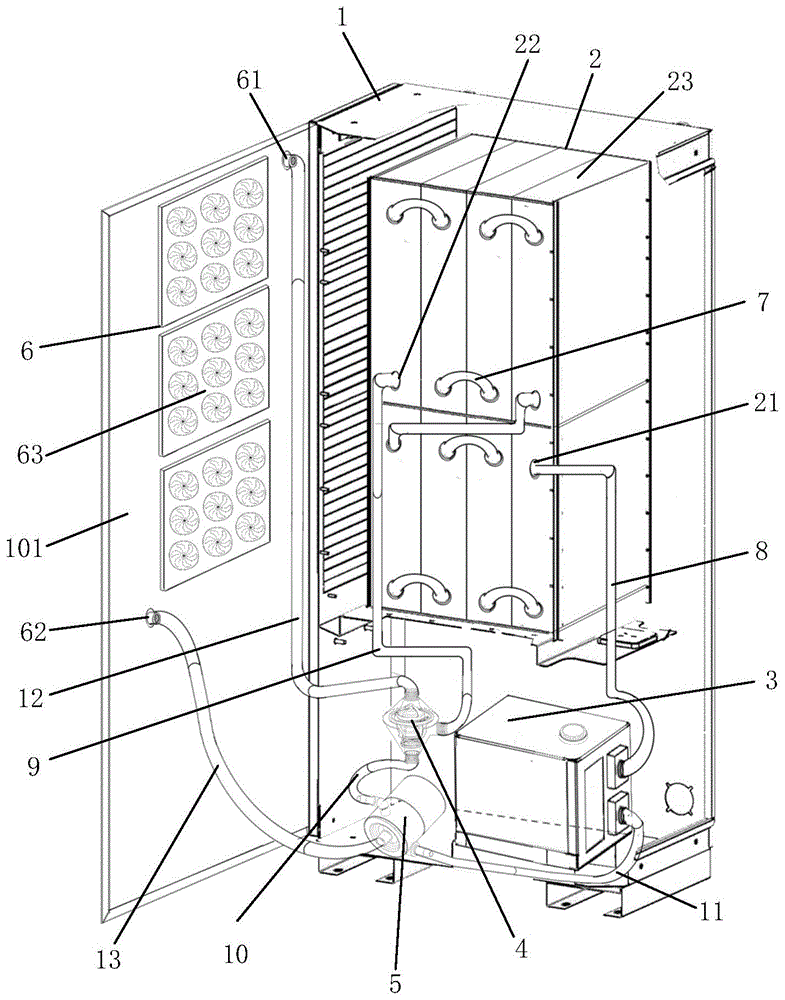
图1示出了本申请一个示例性实施例提供的一种新能源汽车油浸式静音充电桩的内部结构示意图;Figure 1 shows a schematic diagram of the internal structure of an oil-immersed silent charging pile for a new energy vehicle provided by an exemplary embodiment of the present application;
图2示出了本申请一个示例性实施例提供的一种新能源汽车油浸式静音充电桩的换热箱体的结构示意图;Fig. 2 shows a schematic structural diagram of a heat exchange box of an oil-immersed silent charging pile for a new energy vehicle provided by an exemplary embodiment of the present application;
图3示出了本申请一个示例性实施例提供的一种新能源汽车油浸式静音充电桩的外部结构示意图;Fig. 3 shows a schematic diagram of the external structure of an oil-immersed silent charging pile for a new energy vehicle provided by an exemplary embodiment of the present application;
图4示出了本申请一个示例性实施例提供的一种新能源汽车油浸式静音充电桩的散热口格栅的结构示意图;Fig. 4 shows a schematic structural diagram of a radiator grille of an oil-immersed silent charging pile for a new energy vehicle provided by an exemplary embodiment of the present application;
图5示出了本申请一个示例性实施例提供的一种新能源汽车油浸式静音充电桩的鳍片式散热器的结构示意图;Fig. 5 shows a schematic structural diagram of a finned radiator of an oil-immersed silent charging pile for a new energy vehicle provided by an exemplary embodiment of the present application;
图6示出了本申请一个示例性实施例提供的一种新能源汽车油浸式静音充电桩的散热风扇的结构示意图;Fig. 6 shows a schematic structural diagram of a heat dissipation fan of a new energy vehicle oil-immersed silent charging pile provided by an exemplary embodiment of the present application;
图7示出了本申请一个示例性实施例提供的一种新能源汽车油浸式静音充电桩的变压器油冷却箱的结构示意图;Fig. 7 shows a schematic structural diagram of a transformer oil cooling box of a new energy vehicle oil-immersed silent charging pile provided by an exemplary embodiment of the present application;
图8示出了本申请一个示例性实施例提供的一种新能源汽车油浸式静音充电桩的节温器的结构示意图;Fig. 8 shows a schematic structural diagram of a thermostat of an oil-immersed silent charging pile for a new energy vehicle provided by an exemplary embodiment of the present application;
图9示出了本申请一个示例性实施例提供的一种新能源汽车油浸式静音充电桩的油泵的结构示意图;Fig. 9 shows a schematic structural diagram of an oil pump of an oil-immersed silent charging pile for a new energy vehicle provided by an exemplary embodiment of the present application;
图中:In the picture:
1、充电桩本体;101、后侧板;1. Charging pile body; 101. Rear side panel;
2、换热模块;21、换热模块进油口;22、换热模块出油口;23、换热箱体;231、外箱体;232、内箱体;233、变压器油流通部;2311、第一合页;2312、第一锁扣;2321、第二合页;2322、第二锁扣;2. Heat exchange module; 21. Oil inlet of heat exchange module; 22. Oil outlet of heat exchange module; 23. Heat exchange box; 231. Outer box; 232. Inner box; 233. Transformer oil circulation part; 2311, the first hinge; 2312, the first lock; 2321, the second hinge; 2322, the second lock;
3、变压器油冷却箱;31、冷却箱进油口;32、冷却箱出油口;33、液位显示面;34、注油口;3. Transformer oil cooling box; 31. Oil inlet of cooling box; 32. Oil outlet of cooling box; 33. Liquid level display surface; 34. Oil filling port;
4、节温器;41、节温器进油口;42、节温器第一出油口;43、节温器第二出油口;4. Thermostat; 41. Oil inlet of thermostat; 42. First oil outlet of thermostat; 43. Second oil outlet of thermostat;
5、油泵;51、油泵第一进油口;52、油泵出油口;53、油泵第二进油口;5. Oil pump; 51. The first oil inlet of the oil pump; 52. The oil outlet of the oil pump; 53. The second oil inlet of the oil pump;
6、散热模块;61、散热模块进油口;62、散热模块出油口;63、散热风扇组;64、散热口格栅;65、鳍片式散热器;631、散热风扇;6. Cooling module; 61. Oil inlet of cooling module; 62. Oil outlet of cooling module; 63. Cooling fan group; 64. Cooling port grille; 65. Fin radiator; 631. Cooling fan;
7、第一管道;8、第二管道;9、第三管道;10、第四管道;11、第五管道;12、第六管道;13、第七管道。7. The first pipeline; 8. The second pipeline; 9. The third pipeline; 10. The fourth pipeline; 11. The fifth pipeline; 12. The sixth pipeline; 13. The seventh pipeline.
具体实施方式Detailed ways
下面将结合本申请实施例中的附图,对本申请实施例中的技术方案进行清楚、完整地描述,显然,所描述的实施例仅仅是本申请一部分实施例,而不是全部的实施例。基于本申请中的实施例,本领域普通技术人员在没有做出创造性劳动前提下所获得的所有其他实施例,都属于本申请保护的范围。The following will clearly and completely describe the technical solutions in the embodiments of the application with reference to the drawings in the embodiments of the application. Apparently, the described embodiments are only some of the embodiments of the application, not all of them. Based on the embodiments in this application, all other embodiments obtained by persons of ordinary skill in the art without making creative efforts belong to the scope of protection of this application.
其中,相同的零部件用相同的附图标记表示。需要说明的是,下面描述中使用的词语“前”、“后”、“左”、“右”、“上”和“下”指的是本申请说明书附图中的方向,词语“底面”和“顶面”、“内”和“外”分别指的是朝向或远离特定部件。此外,术语“第一”、“第二”仅用于描述目的,而不能理解为指示或暗示相对重要性或者隐含指明所指示的技术特征的数量。由此,限定有“第一”、“第二”的特征可以明示或者隐含地包括一个或者多个该特征。在本申请说明书的描述中,“多个”的含义是两个或两个以上。Among them, the same components are denoted by the same reference numerals. It should be noted that the words "front", "rear", "left", "right", "upper" and "lower" used in the following description refer to the directions in the accompanying drawings of this application specification, and the word "bottom" and "top", "inner" and "outer" mean toward or away from a particular component, respectively. In addition, the terms "first" and "second" are used for descriptive purposes only, and cannot be interpreted as indicating or implying relative importance or implicitly specifying the quantity of indicated technical features. Thus, a feature defined as "first" or "second" may explicitly or implicitly include one or more of these features. In the description of this specification, "plurality" means two or more.
下面结合附图和实施例对本申请作更进一步的说明。The application will be further described below in conjunction with the accompanying drawings and embodiments.
首先,对本申请实施例中涉及的名词进行简单的介绍:First, a brief introduction to the nouns involved in the embodiments of this application:
充电模块(指的直流快充充电桩),是将输入的三相电网交流电经过三相桥式不可控整流AC/DC电路整流变成直流电,滤波后提供给高频 DC-DC功率变换器,功率变换器经过直直变换为充电桩输出需要的直流,充电模块对电路进行控制、转换,保证了供电电路的稳定性。The charging module (referring to the DC fast charging charging pile) is to convert the input three-phase grid AC power through a three-phase bridge uncontrollable rectification AC/DC circuit into direct current, and provide it to the high-frequency DC-DC power converter after filtering. The power converter converts directly into the DC output required by the charging pile, and the charging module controls and converts the circuit to ensure the stability of the power supply circuit.
节温器,是控制冷却液流动路径的阀门,是一种自动调温装置,通常含有感温组件,借着热胀或冷缩来开启、关掉空气、气体或液体的流动。A thermostat is a valve that controls the flow path of coolant. It is an automatic temperature-regulating device that usually contains a temperature-sensing component that opens and closes the flow of air, gas, or liquid by thermal expansion or contraction.
实施例一Embodiment one
图1示出了本申请一个示例性实施例提供的一种新能源汽车油浸式静音充电桩的内部结构示意图,该新能源汽车油浸式静音充电桩包括充电桩本体1,该充电桩本体1呈内部中空的箱体状且由钣金组装而成。充电桩本体1内安装有换热模块2、变压器油冷却箱3、节温器4以及油泵5;换热模块2包括多个换热箱体23,每个换热箱体23内均安装有一个充电模块,多个换热箱体23之间串联连通,多个换热箱体23串联连通后形成换热模块进油口21以及换热模块出油口22。请参阅图7,变压器油冷却箱 3具有冷却箱进油口31以及冷却箱出油口32;请参阅图8,节温器4具有节温器进油口41以及节温器第一出油口42,节温器进油口41以及节温器第一出油口42上均安装有电磁阀;请参阅图9,油泵5具有油泵第一进油口51以及油泵出油口52;结合图1、图7、图8和图9,多个换热箱体23 之间通过第一管道7串联连通,冷却箱出油口32与换热模块进油口21通过第二管道8连通,换热模块出油口22与节温器进油口41通过第三管道 9连通,节温器第一出油口42与油泵第一进油口51通过第四管道10连通,油泵出油口52与冷却箱进油口31通过第五管道11连通。Figure 1 shows a schematic diagram of the internal structure of a new energy vehicle oil-immersed silent charging pile provided by an exemplary embodiment of the present application. The new energy vehicle oil-immersed silent charging pile includes a charging
在本申请实施例中,充电模块与外部的给新能源汽车充电的充电枪电性连接,充电模块密封地置于换热箱体23内,并且与换热箱体23内流通的变压器油隔绝开。可选地,换热箱体23内具有将充电模块与换热箱体 23内流通的变压器油隔绝开的密封隔层。充电模块运行发热时,换热箱体 23内流通的变压器油会吸收其产生的热量进行热传导散热,换热箱体23 内的变压器油在油泵5加压作用下,从换热模块出油口22流出经节温器 4、油泵5后流入变压器油冷却箱3内进行冷却降温,最后变压器油冷却箱3内降温后的变压器油再通过换热模块进油口21流入换热箱体23内,实现循环换热。解决了新能源汽车充电桩使用过程中由于散热风扇产生巨大噪音扰民的问题,同时解决了充电桩散热差、局部高温,内部模块大面积直接与外界环境空气进行交换散热效率低,且容易使得灰尘堆积在元器件模块上加剧发热、甚至短路的问题。在一个示例中,变压器油冷却箱3 上还具有液位显示面33以及注油口34,便于观察变压器油冷却箱3内变压器油的液位以及便于加注变压器油。In the embodiment of the present application, the charging module is electrically connected to the external charging gun for charging new energy vehicles, and the charging module is sealed in the
实施例二Embodiment two
在一个可选的实施例中,图2示出了本申请一个示例性实施例提供的一种新能源汽车油浸式静音充电桩的换热箱体的结构示意图,该换热箱体 23包括外箱体231以及内箱体232,内箱体232置于外箱体231内,充电模块置于内箱体232内,内箱体232与外箱体231之间形成有变压器油流通部233,变压器油流通部233内流通有变压器油,多个换热箱体23内的变压器油流通部233之间串联连通。外箱体231的顶面一侧安装有第一合页2311,另一侧安装有第一锁扣2312,实现外箱体231顶面的开合连接;内箱体232的顶面一侧安装有第二合页2321,另一侧安装有第二锁扣 2322,实现内箱体232顶面的开合连接。In an optional embodiment, FIG. 2 shows a schematic structural diagram of a heat exchange box of a new energy vehicle oil-immersed silent charging pile provided by an exemplary embodiment of the present application. The
在本申请实施例中,外箱体231的一侧壁上部和下部分别开设有输入口以及输出口,该输入口以及输出口与变压器油流通部233连通,多个外箱体231通过输入口以及输出口首尾相接实现多个变压器油流通部233的串联连通,串联后第一组外箱体231的输入口即为换热模块进油口21,串联后最后一组外箱体231的输出口即为换热模块出油口22。通过内箱体 232的设置将充电模块与变压器油流通部233内流通的变压器油隔绝开。需要说明的是,外箱体231以及内箱体232的顶面开合处均安装有密封条,并且变压器油流通部233内流通的变压器油不到顶,没过外箱体231 侧壁开设的输入口或输出口就行。In the embodiment of the present application, the upper and lower parts of the side wall of the
实施例三Embodiment Three
在一个可选的实施例中,请参阅图1和图3,充电桩本体1的后侧具有后侧板101,后侧板101上沿竖直方向安装有多个均匀间隔分布的散热模块6。请参阅图1、图3、图4和图5,散热模块6包括散热风扇组63、散热口格栅64以及鳍片式散热器65,散热风扇组63安装于后侧板101的内侧,散热口格栅64安装于后侧板101的外侧,鳍片式散热器65位于散热风扇组63与散热口格栅64之间;多个鳍片式散热器65之间串联连通,多个鳍片式散热器65串联连通后形成散热模块进油口61以及散热模块出油口62;节温器4还具有节温器第二出油口43,节温器第二出油口 43上安装有电磁阀,油泵5还具有油泵第二进油口53,散热模块进油口61与节温器第二出油口43通过第六管道12连通,散热模块出油口62与油泵第二进油口53通过第七管道13连通。请参阅图1和图6,散热风扇组63包括多组均匀间隔分布的散热风扇631。In an optional embodiment, please refer to FIG. 1 and FIG. 3 , the rear side of the charging
在本申请实施例中,鳍片式散热器65由若干组鳍片以及蛇形管组成,蛇形管来回穿过若干组鳍片,蛇形管的两端分别为流入口以及流出口,多个鳍片式散热器65通过流入口以及流出口首尾相接实现多个鳍片式散热器65的串联连通,串联后第一组鳍片式散热器65的流入口即为散热模块进油口61,串联后最后一组鳍片式散热器65的流出口即为散热模块出油口62。变压器油在鳍片式散热器65散热冷却下,再配合散热风扇组63以及散热口格栅64大大提升了变压器油的冷却降温效率,另外散热口格栅64的设置可以有效阻止雨水、杂质进入充电桩内部。多组散热风扇631拼接的设置,通过智能控制,不但可以减小噪声,可以做到不同季节、不同温度时风扇的开关数量,而且还可以降低传统充电桩由于仅有风扇损坏无法散热造成事故的危险,因为多组小功率小型散热电扇631损坏一个或多个时,其他电扇仍可以使用。除此之外,多组小功率散热风扇 631损坏时方便拆卸维护。In the embodiment of the present application, the
接下来,对本申请实施例中所涉及的一种新能源汽车油浸式静音充电桩的工作原理进行说明。Next, the working principle of an oil-immersed silent charging pile for new energy vehicles involved in the embodiment of the present application will be described.
情况一:当充电桩工作时间较短时,由于充电模块产生热量不高,节温器第二出油口43通过电子阀控制处于关闭状态,换热模块2中的变压器油经过油泵5加压、变压器油冷却箱3冷却降温后再流入换热模块2 中,鳍片式散热器65不参与工作,散热风扇组63也不工作,无风扇噪声产生。Situation 1: When the charging pile works for a short time, because the heat generated by the charging module is not high, the
情况二:当充电桩工作较长时间时,由于充电模块产生热量,节温器第二出油口43通过电子阀控制逐渐打开,一开始时阀门开度较小,只有部分被加热的变压器油流向鳍片式散热器65,其它部分变压器油直接通过回路流回变压器油冷却箱3中;由于整个油路中变压器油温度不是很高,此时散热风扇组63不工作,流经鳍片式散热器65的变压器油自然向空气中散热后通过管道流向油泵5后进入变压器油冷却箱3内进一步冷却降温,最后回到换热模块2中,无风扇噪声产生;当油路中变压器油温度继续升高时,节温器第二出油口43阀门开度变大,鳍片式散热器65温度升高,部分散热风扇组63开始工作散热,此时风扇产生的噪声相对较小。Situation 2: When the charging pile works for a long time, due to the heat generated by the charging module, the
情况三:当充电桩长时间工作时,充电模块持续产生热量,油路中变压器油的温度超过节温器4预设的温度标准值时,节温器第二出油口43 阀门完全打开,同时会自动关闭节温器第一出油口42阀门,此时高温的变压器油全部通过管道流向鳍片式散热器65,散热风扇组63开始全部工作,加速鳍片式散热器65中的变压器油的热量通过45°散热口格栅64散发至空气中的速度,降温后的变压器油经管道流向油泵5再进入变压器油冷却箱3中进一步冷却降温,最后回到换热模块2中,一直循环持续着散热工作。Situation 3: When the charging pile works for a long time, the charging module continues to generate heat, and when the temperature of the transformer oil in the oil circuit exceeds the preset temperature standard value of the
综上所述,本申请提供的一种新能源汽车油浸式静音充电桩散热效果显著,降低噪音明显,同时提高了充电桩的安全性,降低了风险,实现了不同情况下对充电桩内部散热的控制,进一步降低噪音的同时降低了自身对电能的损耗。In summary, the oil-immersed silent charging pile for new energy vehicles provided by this application has a remarkable heat dissipation effect, significantly reduces noise, and at the same time improves the safety of the charging pile, reduces risks, and realizes internal monitoring of the charging pile under different conditions. The control of heat dissipation further reduces the noise and reduces the loss of electric energy.
在本申请公开的实施例中,术语“安装”、“相连”、“连接”、“固定”等术语均应做广义理解,例如,“连接”可以是固定连接,也可以是可拆卸连接,或一体地连接;“相连”可以是直接相连,也可以通过中间媒介间接相连。对于本领域的普通技术人员而言,可以根据具体情况理解上述术语在本发明公开的实施例中的具体含义。In the embodiments disclosed in this application, terms such as "installation", "connection", "connection" and "fixation" should be understood in a broad sense. For example, "connection" can be a fixed connection or a detachable connection. Or integrally connected; "connected" can be directly connected or indirectly connected through an intermediary. Those skilled in the art can understand the specific meanings of the above terms in the embodiments disclosed in the present invention according to specific situations.
以上所述仅是本申请的优选实施方式,应当指出:对于本技术领域的普通技术人员来说,在不脱离本申请原理的前提下,还可以做出若干改进和润饰,这些改进和润饰也应视为本申请的保护范围。The above is only a preferred embodiment of the application, it should be pointed out that for those of ordinary skill in the art, without departing from the principle of the application, some improvements and modifications can also be made, and these improvements and modifications are also It should be regarded as the protection scope of this application.
Claims (8)
Priority Applications (1)
| Application Number | Priority Date | Filing Date | Title |
|---|---|---|---|
| CN202211031228.8A CN115303098A (en) | 2022-08-26 | 2022-08-26 | Oil-immersed mute charging pile for new energy automobile |
Applications Claiming Priority (1)
| Application Number | Priority Date | Filing Date | Title |
|---|---|---|---|
| CN202211031228.8A CN115303098A (en) | 2022-08-26 | 2022-08-26 | Oil-immersed mute charging pile for new energy automobile |
Publications (1)
| Publication Number | Publication Date |
|---|---|
| CN115303098A true CN115303098A (en) | 2022-11-08 |
Family
ID=83863757
Family Applications (1)
| Application Number | Title | Priority Date | Filing Date |
|---|---|---|---|
| CN202211031228.8A Withdrawn CN115303098A (en) | 2022-08-26 | 2022-08-26 | Oil-immersed mute charging pile for new energy automobile |
Country Status (1)
| Country | Link |
|---|---|
| CN (1) | CN115303098A (en) |
Cited By (3)
| Publication number | Priority date | Publication date | Assignee | Title |
|---|---|---|---|---|
| CN116373641A (en) * | 2023-04-23 | 2023-07-04 | 江阴市富仁高科股份有限公司 | Energy-saving efficient heat dissipation charging pile |
| CN117124895A (en) * | 2023-09-12 | 2023-11-28 | 无锡久盛换热器有限公司 | Oil cooler for overcharged piles |
| CN120287878A (en) * | 2025-05-13 | 2025-07-11 | 温州市梦宸进出口有限公司 | A DC charging pile |
-
2022
- 2022-08-26 CN CN202211031228.8A patent/CN115303098A/en not_active Withdrawn
Cited By (5)
| Publication number | Priority date | Publication date | Assignee | Title |
|---|---|---|---|---|
| CN116373641A (en) * | 2023-04-23 | 2023-07-04 | 江阴市富仁高科股份有限公司 | Energy-saving efficient heat dissipation charging pile |
| CN116373641B (en) * | 2023-04-23 | 2024-02-13 | 江阴市富仁高科股份有限公司 | Energy-saving efficient heat dissipation charging pile |
| CN117124895A (en) * | 2023-09-12 | 2023-11-28 | 无锡久盛换热器有限公司 | Oil cooler for overcharged piles |
| CN120287878A (en) * | 2025-05-13 | 2025-07-11 | 温州市梦宸进出口有限公司 | A DC charging pile |
| CN120287878B (en) * | 2025-05-13 | 2025-10-21 | 温州市梦宸进出口有限公司 | A DC charging pile |
Similar Documents
| Publication | Publication Date | Title |
|---|---|---|
| CN218218136U (en) | A liquid-cooled charging pile | |
| CN107839495B (en) | A charging pile and heat dissipation control method | |
| CN209103897U (en) | A kind of high-efficient heat-dissipating transformer applied to thermal power plant | |
| CN210865815U (en) | An intelligent cooling oil-immersed transformer | |
| CN107846047A (en) | A kind of charging pile and cooling control method | |
| CN211530440U (en) | A heat-dissipating safety protection distribution cabinet | |
| CN118174515B (en) | Power conversion equipment and energy storage equipment | |
| CN107575976A (en) | The cooling system in relative closure space | |
| CN113270809B (en) | Feeder terminal cooling device | |
| CN209184046U (en) | A high voltage electric cabinet | |
| CN219642949U (en) | Energy storage system based on temperature adjustment of liquid | |
| CN219144277U (en) | A combined energy storage battery | |
| CN210245263U (en) | Heat radiator for multi-functional transformer | |
| CN213583409U (en) | A heat exchange type internal circulation transformer station | |
| CN108561979A (en) | Electrical apparatus box, off-premises station, photovoltaic air conditioning system and electrical equipment | |
| CN210404503U (en) | High-efficient heat abstractor of transformer substation | |
| CN115313220A (en) | Indoor transformer substation ventilation cooling system with targeted air supply | |
| CN208720368U (en) | Electrical apparatus box, off-premises station, photovoltaic air conditioning system and electrical equipment | |
| CN221960810U (en) | Water-cooled transformer module | |
| CN213937755U (en) | Heat radiator for dc-to-ac converter | |
| CN207378981U (en) | The cooling system in relative closure space | |
| CN223452282U (en) | Energy storage converter convenient to heat dissipation | |
| CN224067513U (en) | High-insulation composite integrated transformer shell | |
| CN221929096U (en) | A prefabricated chamber equipment for phase regulator | |
| CN215645744U (en) | Electrical equipment cooler |
Legal Events
| Date | Code | Title | Description |
|---|---|---|---|
| PB01 | Publication | ||
| PB01 | Publication | ||
| SE01 | Entry into force of request for substantive examination | ||
| SE01 | Entry into force of request for substantive examination | ||
| WW01 | Invention patent application withdrawn after publication | ||
| WW01 | Invention patent application withdrawn after publication |
Application publication date: 20221108 |