CN115301786B - Bending device for pipe machining - Google Patents
Bending device for pipe machining Download PDFInfo
- Publication number
- CN115301786B CN115301786B CN202211231060.5A CN202211231060A CN115301786B CN 115301786 B CN115301786 B CN 115301786B CN 202211231060 A CN202211231060 A CN 202211231060A CN 115301786 B CN115301786 B CN 115301786B
- Authority
- CN
- China
- Prior art keywords
- bending
- wheel
- transmission
- pipe
- gear
- Prior art date
- Legal status (The legal status is an assumption and is not a legal conclusion. Google has not performed a legal analysis and makes no representation as to the accuracy of the status listed.)
- Active
Links
- 238000005452 bending Methods 0.000 title claims abstract description 228
- 238000003754 machining Methods 0.000 title claims description 14
- 230000007246 mechanism Effects 0.000 claims abstract description 116
- 230000005540 biological transmission Effects 0.000 claims abstract description 101
- 238000012545 processing Methods 0.000 claims abstract description 26
- 230000008859 change Effects 0.000 claims abstract description 24
- 230000002596 correlated effect Effects 0.000 claims description 4
- 230000001360 synchronised effect Effects 0.000 claims description 3
- 239000002184 metal Substances 0.000 abstract description 2
- 238000010586 diagram Methods 0.000 description 5
- 230000009471 action Effects 0.000 description 3
- 230000017525 heat dissipation Effects 0.000 description 3
- 238000013459 approach Methods 0.000 description 2
- 238000000034 method Methods 0.000 description 2
- 230000008569 process Effects 0.000 description 2
- 230000009286 beneficial effect Effects 0.000 description 1
- 244000309464 bull Species 0.000 description 1
- 238000006243 chemical reaction Methods 0.000 description 1
- 230000008878 coupling Effects 0.000 description 1
- 238000010168 coupling process Methods 0.000 description 1
- 238000005859 coupling reaction Methods 0.000 description 1
- 238000004519 manufacturing process Methods 0.000 description 1
- 239000000463 material Substances 0.000 description 1
- 238000012986 modification Methods 0.000 description 1
- 230000004048 modification Effects 0.000 description 1
- 238000012827 research and development Methods 0.000 description 1
Images




Classifications
-
- B—PERFORMING OPERATIONS; TRANSPORTING
- B21—MECHANICAL METAL-WORKING WITHOUT ESSENTIALLY REMOVING MATERIAL; PUNCHING METAL
- B21D—WORKING OR PROCESSING OF SHEET METAL OR METAL TUBES, RODS OR PROFILES WITHOUT ESSENTIALLY REMOVING MATERIAL; PUNCHING METAL
- B21D7/00—Bending rods, profiles, or tubes
- B21D7/02—Bending rods, profiles, or tubes over a stationary forming member; by use of a swinging forming member or abutment
- B21D7/024—Bending rods, profiles, or tubes over a stationary forming member; by use of a swinging forming member or abutment by a swinging forming member
Landscapes
- Engineering & Computer Science (AREA)
- Mechanical Engineering (AREA)
- Bending Of Plates, Rods, And Pipes (AREA)
Abstract
The invention is suitable for the technical field of metal pipe bending, and provides a bending device for pipe processing, which comprises a bending frame, a limiting mechanism, a bending mechanism, a transmission device and a speed change device, wherein the bending mechanism and the limiting mechanism are arranged on the bending frame, the bending mechanism is provided with a bending wheel, the transmission device can change the distance between the bending wheel and the limiting mechanism according to the diameters of different pipes, and the speed change device adjusts the transmission ratio of the bending mechanism and the transmission device according to the changed distance of the transmission device to change the bending force, so that the problem that the bending force cannot be changed according to the diameter of the pipe is solved, the bending efficiency is high, energy is saved, and the application range of the bending device is enlarged.
Description
Technical Field
The invention relates to the technical field of metal pipe bending, in particular to a bending device for pipe processing.
Background
Tubular product generally uses in production life, and the shape requirement to tubular product differs, and wherein there are many needs to bend to tubular product, nevertheless at present to bending of tubular product, generally rotate the mould through people's manual and bend to tubular product, so manual operation is lower to the efficiency that tubular product was bent, because manual operation's error is great, also causes the precision of bending to tubular product not high easily, consequently need research and development an efficiency and the higher bender of precision of bending to tubular product.
For example, chinese patent document with application publication No. CN113695479B discloses an efficient bending device for a heat dissipation tube, which mainly aims at bending of the heat dissipation tube, and realizes the conversion of clamping and bending by adjusting a driving sleeve, but the bending force of the heat dissipation tube is the same for pipes with different diameters, so that when a pipe with a smaller diameter is processed, energy is wasted, the bending force cannot be changed according to pipes with different diameters, the bending efficiency is low, and the application range of a bending machine device is small.
Disclosure of Invention
On the basis, the bending device for processing the pipes is necessary to solve the problems that the existing bending machine cannot adjust the bending strength according to the pipes with different diameters, the bending efficiency is low, and the application range of the bending machine is small.
The above purpose is realized by the following technical scheme:
a bending device for processing a pipe comprises a bending frame, a limiting mechanism, a bending mechanism, a transmission device and a speed change device, wherein the bending mechanism and the limiting mechanism are arranged on the bending frame, and a bending wheel is arranged on the bending mechanism; the transmission device comprises a motor shaft and a gear disc, the gear disc is arranged on the motor shaft, the motor shaft can drive the gear disc to rotate, the gear disc is in transmission connection with the bending wheel, the gear disc can drive the bending wheel to move towards the direction close to the limiting mechanism by rotating, the pipe is arranged between the bending wheel and the limiting mechanism, and the distance between the bending wheel and the limiting mechanism is positively correlated with the diameter of the pipe;
the speed change device is in transmission connection with the bending mechanism and the transmission device, the speed change device comprises a reducing belt wheel and an adjusting mechanism, the reducing belt wheel is arranged on the adjusting mechanism, the adjusting mechanism can adjust the diameter of the reducing belt wheel, the diameter of the reducing belt wheel is adjusted to adjust the transmission ratio of the bending mechanism and the transmission device, and therefore the bending force is changed.
In one embodiment, the bending wheel can slide along the direction perpendicular to the placement direction of the pipes, and the transmission device can adjust the distance between the bending wheel and the limiting mechanism according to different diameters of the pipes.
In one embodiment, before the bending mechanism performs the bending operation, the transmission device is in transmission connection with the bending wheel, the speed change device and the bending wheel are in synchronous transmission, the transmission device adjusts the speed change device according to the distance between the bending wheel and the limiting mechanism, the speed change device adjusts the transmission ratio of the bending mechanism and the transmission device according to the changed distance of the transmission device, when the bending operation is started, the transmission device is in transmission connection with the bending mechanism, and the bending mechanism starts to perform the bending operation according to the changed transmission ratio.
In one embodiment, the transmission device further comprises a belt wheel cylinder and a movable sleeve, the belt wheel cylinder and the gear disc are rotatably connected to the motor shaft, the belt wheel cylinder is in transmission connection with the bending mechanism, the movable sleeve is arranged on the motor shaft and can synchronously rotate with the motor shaft, the movable sleeve can slide up and down along the motor shaft, the belt wheel cylinder and the gear disc can be respectively in transmission connection with the movable sleeve, and the movable sleeve can control the transmission device to be in transmission connection with the bending wheel and the bending mechanism.
In one embodiment, a large gear shaft is arranged on the reducing belt wheel, the reducing belt wheel is fixedly connected with the large gear shaft, the reducing belt wheel and the large gear shaft are rotatably connected onto the adjusting mechanism, the large gear shaft is in transmission connection with the bending mechanism, and the large gear shaft transmits the changed transmission speed to the bending mechanism.
In one embodiment, the adjusting mechanism comprises an adjusting sleeve, a pinion shaft and a second gear, the adjusting sleeve is arranged on the pinion shaft, the second gear is fixedly arranged on the pinion shaft, the positions of the adjusting sleeve can be adjusted by the pinion shaft and the second gear, and the diameter of the reducing belt wheel can be adjusted by the adjusting sleeve.
In one embodiment, the adjusting sleeve is rotatably connected to the pinion shaft, the adjusting sleeve can slide along the axial direction of the pinion shaft, and the diameter of the reducing belt wheel is adjusted through the axial sliding of the adjusting sleeve.
In one embodiment, the limiting mechanism is slidably connected to the bending frame, and when the limiting mechanism slides to a preset position, the bending mechanism starts to perform bending operation.
In one embodiment, an elastic reset element is arranged between the limiting mechanism and the bending frame, and the elastic reset element always enables the limiting mechanism to return to an initial position or has a tendency of returning to an initial state.
The beneficial effects of the invention are:
the invention provides a bending device for processing a pipe, which comprises a bending frame, a limiting mechanism, a bending mechanism, a transmission device and a speed change device, wherein the bending mechanism and the limiting mechanism are arranged on the bending frame, the bending mechanism is provided with a bending wheel, the transmission device can change the distance between the bending wheel and the limiting mechanism according to different pipe diameters, and the speed change device adjusts the transmission ratio of the bending mechanism and the transmission device according to the changed distance of the transmission device to change the bending force, so that the problem that the bending machine cannot change the bending force according to the pipe diameter is solved, the bending efficiency is improved, the energy is saved, and the application range of the bending device is enlarged.
Drawings
Fig. 1 is a structural view of a bending apparatus for pipe machining according to an embodiment of the present invention;
fig. 2 is a schematic partial structural view of a bending apparatus for processing a pipe according to an embodiment of the present invention;
FIG. 3 is an enlarged view of a portion of a bending device I for pipe machining in FIG. 2;
FIG. 4 is a diagram illustrating an initial operation state of the bending apparatus for machining a pipe in FIG. 1 according to the present embodiment;
FIG. 5 is a state diagram of the bending apparatus for pipe machining in FIG. 1 according to the present embodiment when a bending operation is started;
FIG. 6 is a state diagram of the bending apparatus for processing a pipe material in FIG. 1 according to the present embodiment when bending operation is completed;
FIG. 7 isbase:Sub>A cross-sectional view of one of the bending apparatuses for pipe machining of FIG. 4 taken along the direction A-A;
FIG. 8 is a cross-sectional view of one of the bending apparatuses for tube machining of FIG. 4 taken along the direction B-B;
FIG. 9 is a cross-sectional view of a bending apparatus for pipe machining of FIG. 5 taken along the direction D-D
FIG. 10 is a cross-sectional view of the clamping mechanism of a bending apparatus for tube processing of FIG. 4 taken along the direction C-C;
FIG. 11 is a schematic structural diagram of a transmission device in a bending device for pipe machining according to another embodiment of the present invention;
FIG. 12 is a cross-sectional view of the embodiment of the bending apparatus actuator of FIG. 11 for pipe machining;
FIG. 13 is a schematic structural diagram of a speed changing device in a bending apparatus for pipe processing according to another embodiment of the present invention;
FIG. 14 is a structural cross-sectional view of a speed changing device of the bending device for pipe machining in the embodiment of FIG. 13.
Wherein:
100. a bending frame; 110. a sliding groove;
200. a bending mechanism; 210. a rotating plate; 211. a limiting groove; 212. an inner gear ring; 213. a chute; 220. bending wheels; 221. a bevel gear shaft; 222. a movable block; 230. a first gear;
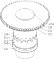
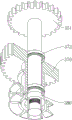
300. a limiting mechanism; 310. a limiting wheel; 311. a limiting frame; 312. a spacing pin; 313. a first spring; 320. a gear plate; 321. a straight tooth surface; 322. a beveled tooth surface; 323. a wheel disc gear ring; 330. a movable sleeve; 331. a lower gear ring; 332. a limiting disc; 333. a first upper ring gear; 334. a second spring; 340. a pulley drum; 341. a second upper ring gear; 342. a drive pulley; 350. a pinion shaft; 351. a second gear; 360. a variable diameter pulley; 361. a belt; 362. a tension pulley; 370. a large gear shaft; 371. positioning rings; 372. a bearing; 373. a positioning frame; 380. an adjustment sleeve;
400. a clamping mechanism; 410. a movable clamping block; 420. a lead screw; 430. fixing the clamping block;
500. a pipe to be processed;
600. an electric motor; 610. a motor shaft; 611. and a stop block.
Detailed Description
In order to make the objects, technical solutions and advantages of the present invention more apparent, the present invention is further described in detail by the following embodiments in conjunction with the accompanying drawings. It should be understood that the specific embodiments described herein are merely illustrative of the invention and are not intended to limit the invention.
The ordinal numbers used herein for the components, such as "first," "second," etc., are used merely to distinguish between the objects described, and do not have any sequential or technical meaning. The term "connected" and "coupled" as used herein includes both direct and indirect connections (couplings), unless otherwise specified. In the description of the present invention, it is to be understood that the terms "upper", "lower", "front", "rear", "left", "right", "vertical", "horizontal", "top", "bottom", "inner", "outer", "clockwise", "counterclockwise", and the like, indicate orientations or positional relationships based on those shown in the drawings, and are only for convenience of description and simplicity of description, but do not indicate or imply that the referenced devices or elements must have a particular orientation, be constructed and operated in a particular orientation, and thus, are not to be construed as limiting the present invention.
In the present invention, unless expressly stated or limited otherwise, the first feature "on" or "under" the second feature may be directly contacting the second feature or the first and second features may be indirectly contacting each other through intervening media. Also, a first feature "on," "over," and "above" a second feature may be directly or diagonally above the second feature, or may simply indicate that the first feature is at a higher level than the second feature. A first feature being "under," "below," and "beneath" a second feature may be directly under or obliquely under the first feature, or may simply mean that the first feature is at a lesser elevation than the second feature.
The following describes a bending device for pipe machining according to the present invention with reference to fig. 1 to 14.
In one embodiment, referring to fig. 1, 2 and 4, the invention provides a bending device for pipe processing, which comprises a bending frame 100, a bending mechanism 200, a limiting mechanism 300, a clamping mechanism 400, a transmission device and a speed changing device. The bending mechanism 200, the limiting mechanism 300 and the clamping mechanism 400 are all arranged on the bending frame 100, the bending mechanism 200 is provided with a bending wheel 220, the transmission device adjusts the distance between the bending wheel 220 and the limiting mechanism 300 according to the different diameters of the pipes 500 to be processed, the transmission device changes the transmission ratio between the bending mechanism 200 and the transmission device according to the different distances between the bending wheel 220 and the limiting mechanism 300, and then the bending speed of the bending mechanism 200 is changed, so that the bending force can be changed according to the different diameters of the pipes 500 to be processed. During operation, the pipe 500 to be processed is clamped by the clamping mechanism 400, for example, when the diameter of the pipe 500 to be processed is smaller, the longer the distance that the bending wheel 220 moves in the direction close to the pipe 500 to be processed is, the transmission ratio between the bending mechanism 200 and the transmission device is reduced by the speed changing device, the bending speed of the bending mechanism 200 is increased, and the torque is reduced; when the diameter of the pipe 500 to be processed is larger, the distance that the bending mechanism 200 moves towards the direction close to the pipe 500 to be processed is shorter, the transmission ratio between the bending mechanism 200 and the transmission device is increased by the speed change device compared with the pipe 500 to be processed with a smaller processing diameter, the bending speed is lower than that of the pipe 500 to be processed with a smaller processing diameter, and the torque is larger than that of the pipe 500 to be processed with a smaller processing diameter. The bending machine has the advantages that different bending force degrees are adopted according to different diameters of pipes, so that the efficiency is high, the resources are saved, and the application range of the bending machine is enlarged.
In one embodiment, referring to fig. 1, 2, 3, 4, and 7, the bending mechanism 200 includes a rotating plate 210, a limit groove 211, a slide groove 213, a bevel gear shaft 221, a movable block 222, and a first gear 230. The bending mechanism 200 is provided with a bending wheel 220, the bending wheel 220 is hinged with a movable block 222, the movable block 222 is connected with the rotating plate 210 in a sliding manner, the movable block 222 can slide through the rotation of a bevel gear shaft 221, and the movable block 222 drives the bending wheel 220 to slide towards the direction close to the limiting wheel 310 and the direction perpendicular to the pipe 500 to be processed until the pipe 500 to be processed is contacted. In the process that the bending wheel 220 starts to slide until the bending wheel 220 contacts the pipe 500 to be processed, the distance between the bending wheel 220 and the limiting mechanism 300 is adjusted by the transmission device. The bevel gear shaft 221 rotates in the sliding groove 213, the rotating plate 210 is slidably connected to the bending frame 100, the rotating plate 210 slides along the sliding groove 110, the inner side surface of the sliding portion of the rotating plate 210 along the sliding groove 110 is provided with an inner gear ring 212, and the rotating plate 210 is provided with a limiting groove 211 along the inner side in the rotating direction. When the bending is started, the rotating plate 210 drives the bending wheel 220 to slide along the sliding groove 110, and the bending wheel 220 bends the pipe 500 to be processed.
In one embodiment, referring to fig. 1, 2 and 5, when the bending operation is not started, the transmission device is in transmission connection with the bending wheel 220, the transmission device adjusts the distance between the bending wheel 220 and the limiting mechanism 300 according to the diameter of the pipe 500 to be processed, the transmission device is in transmission connection with the transmission device and the bending wheel 220 at the same time, the transmission device synchronously adjusts the transmission device according to the moving distance of the bending wheel 220, the transmission device adjusts the transmission ratio between the bending mechanism 200 and the transmission device according to the diameter of the pipe 500 to be processed, after the adjustment, the bending operation is started, the transmission device is in transmission connection with the bending mechanism 200 at the moment, and the transmission device drives the bending mechanism 200 to start the bending operation according to the changed transmission ratio.
In one embodiment, referring to fig. 1, 2, 7, 9, 11 and 12, the transmission includes a motor shaft 610, a gear plate 320, a movable sleeve 330, a second spring 334, a pulley drum 340 and a stop 611. The pulley barrel 340, the movable sleeve 330 and the gear wheel 320 are sequentially sleeved on the motor shaft 610 from bottom to top, four grooves are formed in the movable sleeve 330, the movable sleeve 330 and the motor shaft 610 are limited to rotate relative to each other under the combined action of four fixed stoppers 611 on the motor shaft 610, the motor shaft 610 and the movable sleeve 330 rotate synchronously, a second spring 334 is arranged below the stoppers 611, the bottom of the second spring 334 is in contact with the bottom of the groove, the top of the second spring 334 is in contact with the stoppers 611, the movable sleeve 330 can slide up and down along the axial direction of the motor shaft 610, the pulley barrel 340 and the gear wheel 320 are rotatably connected to the motor shaft 610, a helical tooth surface 322 on the gear wheel 320 is meshed with the bevel gear shaft 221, the gear wheel 320 can drive the bevel gear shaft 221 to rotate, the bevel gear shaft 221 rotates to drive the movable block 222 to slide, the movable block 222 drives the bending wheel 220 to slide, a transmission pulley 342 is arranged on the lower half portion of the pulley barrel 340, and the transmission pulley 342 is in transmission connection with the bending mechanism 200. When the bending operation is not started, as shown in fig. 7, the first upper gear ring 333 arranged at the top of the movable sleeve 330 is engaged with the wheel disc gear ring 323 arranged at the bottom of the gear disc 320, the motor shaft 610 drives the gear disc 320 to rotate, and the gear disc 320 drives the bending wheel 220 to slide. When the bending operation is started, as shown in fig. 9, the lower gear ring 331 of the movable sleeve 330 is engaged with the second upper gear ring 341 of the pulley drum 340, the motor shaft 610 drives the pulley drum 340 to rotate, the driving pulley 342 on the pulley drum 340 rotates synchronously, the driving pulley 342 is in transmission connection with the bending mechanism 200, and the motor shaft 610 drives the bending mechanism 200 to start the bending operation.
In one embodiment, referring to fig. 1, 4 and 13, the speed changing device includes a reducing belt wheel 360 and an adjusting mechanism, the reducing belt wheel 360 is disposed on the adjusting mechanism, and the adjusting mechanism can adjust the diameter of the reducing belt wheel 360 according to the diameter of the pipe 500 to be processed, so as to change the transmission ratio between the bending mechanism 200 and the transmission device, and adjust the bending force according to the pipe 500 to be processed with different diameters.
In one embodiment, referring to fig. 1, 2, 8, 13 and 14, the reducing pulley 360 is sleeved on the adjusting mechanism through a bearing 372, the reducing pulley 360 and the large gear shaft 370 are fixedly connected, a positioning ring 371 is arranged between the large gear shaft 370 and the reducing pulley 360, a positioning frame 373 is arranged inside the bending device for processing the pipe, the positioning ring 371 is positioned on the positioning frame 373 and used for fixing the speed changing device, the large gear shaft 370 is in gear transmission with the bending mechanism 200, and the large gear shaft 370 transmits the changed transmission speed to the bending mechanism 200.
In one embodiment, referring to fig. 13 and 14, the adjusting mechanism includes a pinion shaft 350, a second gear 351, a bull gear shaft 370, and an adjusting sleeve 380, the second gear 351 is fixedly disposed on the top of the pinion shaft 350, the adjusting sleeve 380 is disposed on the pinion shaft 350, and the adjusting sleeve 380 is used for adjusting the diameter of the reducing pulley 360.
In one embodiment, referring to fig. 13 and 14, the adjusting sleeve 380 is arranged inside the reducing pulley 360, the outer surface of the adjusting sleeve 380 is always in contact with the inner surface of the reducing pulley 360, the adjusting sleeve 380 is rotatably connected to the pinion shaft 350, threads are arranged on the pinion shaft 350, the pinion shaft 350 is in threaded connection with the adjusting sleeve 380, the adjusting sleeve 380 can slide up and down on the pinion shaft 350, and the diameter of the reducing pulley 360 changes with the change of the diameter of the adjusting sleeve 380 in contact with the adjusting sleeve 380 because the surface of the adjusting sleeve 380 is a conical surface with an upper diameter smaller than a lower diameter.
In one embodiment, referring to fig. 1, 2, 3, 8, 9 and 12, the spacing mechanism 300 includes a spacing wheel 310, a spacing bracket 311 and a spacing pin 312. The limiting wheel 310 is connected to the bending frame 100 in a sliding manner, the limiting wheel 310 can slide along the direction perpendicular to the placement direction of the pipe 500 to be processed, the limiting frame 311 is arranged below the limiting wheel 310, the position of the movable sleeve 330 is controlled by the limiting frame 311 and the limiting disc 332, and the limiting pin 312 is further arranged below the limiting wheel 310. In the initial state of the device, the stopper pin 312 is located in the stopper groove 211. When the limiting wheel 310 slides to the limit position, the limiting pin 312 is separated from the limiting groove 211, the limiting frame 311 is separated from the limiting disc 332, the changing state is from the position below the limiting disc 332 by the limiting frame 311 shown in fig. 8 to the position where the limiting frame 311 is flush with the limiting disc 332 shown in fig. 9, the limiting frame 311 no longer limits the limiting disc 332, and the bending mechanism 200 starts to perform the bending operation.
In one embodiment, referring to fig. 1 and 7, a groove is formed on the lower surface of the limiting wheel 310, a first spring 313 is arranged in the groove, two ends of the first spring 313 are respectively connected with the bending frame 100 and the limiting wheel 310, and when the bending operation is completed, the limiting wheel 310 is restored to the initial state through the first spring 313.
In one embodiment, referring to fig. 4 and 10, the clamping mechanism 400 includes a movable clamping block 410, a lead screw 420, and a fixed clamping block 430. The movable clamping block 410 is in threaded connection with the lead screw 420, the rotation of the lead screw 420 can drive the movable clamping block 410 to move towards the direction close to the fixed clamping block 430, and the fixed clamping block 430 and the movable clamping block 410 act together to clamp the pipe 500 to be processed.
The following describes a specific working process of a bending device for processing a pipe according to an embodiment of the present invention with reference to the foregoing embodiment:
when the bending device for pipe processing is used for bending pipes 500 to be processed with different diameters, the pipes 500 to be processed are fixed by the clamping mechanism 400, the motor 600 is started at the moment, the bending wheel 220 slides towards the direction close to the limiting wheel 310 and in the direction perpendicular to the pipes 500 to be processed until the pipes 500 to be processed are contacted, the gear disc 320 is simultaneously meshed with the second gear 351 and the bevel gear shaft 221, the moving distance of the bending wheel 220 is synchronous with the rotation of the second gear 351, the pinion shaft 350 and the second gear 351 are fixedly connected, the downward moving distance of the adjusting sleeve 380 on the pinion shaft 350 is positively correlated with the moving distance of the bending wheel 220, the longer the downward moving distance of the adjusting sleeve 380 is, the smaller the diameter of the reducing pulley 360 is, the transmission ratio between the transmission pulley 342 and the reducing pulley 360 is changed by changing the diameter of the reducing pulley 360, the reducing pulley 360 is sleeved on the pinion 350 through the bearing 372, the pulley 360 and the large gear shaft 370 are fixedly connected, the reducing pulley shaft 370 is meshed with the first gear, when the bending device starts to bend, the large transmission pulley 230 transmits the transmission speed of the large transmission pulley 370 to the rotating plate 210, and the gear shaft 210 is smaller; the slower the transmission speed, the bigger the torque, the bigger the bending force, the rotating plate 210 drives the bending wheel 220 to perform the bending operation on the pipe 500 to be processed, so that the pipe with different diameters can be bent according to different bending forces, namely, the pipe with a large processing diameter has large force and the pipe with a small processing diameter has small force, the bending efficiency is high, and meanwhile, the application range of the bending device is enlarged.
In an initial operating state, as shown in fig. 2, the disk ring gear 323 on the gear disk 320 is engaged with the first upper ring gear 333 of the movable sleeve 330, the helical tooth surface 322 on the gear disk 320 is engaged with the bevel gear shaft 221 all the time, the stopper pin 312 is in the stopper groove 211, and the diameter of the variable diameter pulley 360 is the largest in the initial state.
After the pipe 500 to be processed is put in, the state is shown in fig. 4. The movable clamping block 410 slides on the lead screw 420, and is cooperated with the fixed clamping block 430 to clamp the pipe 500 to be processed. After the pipe 500 to be processed is clamped, the motor 600 is started, the motor 600 drives the motor shaft 610 to rotate, and due to the action of the limiting frame 311 and the limiting disc 332 on the movable sleeve 330, the first upper gear ring 333 of the movable sleeve 330 is meshed with the wheel disc gear ring 323 on the gear disc 320, and the movable sleeve 330 drives the gear disc 320 to rotate. The helical tooth surface 322 on the gear plate 320 is meshed with the bevel gear shaft 221, the rotation of the gear plate 320 further drives the rotation of the bevel gear shaft 221, the movable block 222 connected to the bevel gear shaft 221 slides along with the rotation of the bevel gear shaft 221, and the movable block 222 drives the bending wheel 220 to approach the pipe 500 to be processed, and the state is shown in fig. 5.
When the bending wheel 220 is close to the pipe 500 to be processed until the pipe 500 to be processed is contacted, the straight tooth surface 321 on the gear disc 320 is meshed with the second gear 351, the gear disc 320 drives the pinion shaft 350 to rotate, the rotation of the pinion shaft 350 enables the adjusting sleeve 380 to move downwards, so that the diameter of the reducing pulley 360 is changed, and because the gear disc 320 is meshed with the bevel gear shaft 221 and the second gear 351 simultaneously, the distance that the bending wheel 220 moves is positively correlated with the downward sliding distance of the adjusting sleeve 380. In an initial state, the diameter of the variable diameter pulley 360 is the largest, the torque is the largest, the smaller the diameter of the pipe 500 to be processed is, the longer the moving distance of the bending wheel 220 is, the more the number of rotation turns of the pinion shaft 350 is, and the longer the downward moving distance of the adjusting sleeve 380 on the pinion shaft 350 is, so that the smaller the diameter of the variable diameter pulley 360 is, the higher the rotation speed is, and the smaller the torque is. The larger the diameter of the variable diameter pulley 360 is, the larger the torque is, and the smaller the diameter is, the smaller the torque is.
After the bending wheel 220 approaches and contacts the pipe 500 to be processed, the state is as shown in fig. 5, the bending wheel 220 pushes the limiting wheel 310 to slide rightwards, after the limiting wheel 310 slides to the limit, the limiting pin 312 is pulled out of the limiting groove 211, at this time, the rotating plate 210 is no longer limited and can slide along the sliding groove 110, meanwhile, the limit of the limiting frame 311 to the movable sleeve 330 is released, the movable sleeve 330 moves downwards under the action of the second spring 334, so that the lower gear ring 331 of the movable sleeve 330 is meshed with the second upper gear ring 341 of the belt pulley barrel 340, the motor shaft 610 drives the driving belt pulley 342 on the belt pulley barrel 340 to rotate, the driving belt pulley 342 drives the reducing belt pulley 360 to rotate through the connection of the belt 361 and the reducing belt pulley 360, the tensioning pulley 362 is arranged on the outer side of the belt 361 connected between the reducing belt pulley 360 and the driving belt pulley 342, so that the belt 361 is always in a tensioned state, the reducing belt pulley 360 drives the large gear shaft 370 to rotate, the large gear shaft 370 drives the first gear 230 to rotate, the first gear 230 drives the rotating plate 210 to rotate through the inner gear ring 212, and further drives the bending wheel 220 arranged on the rotating plate 210 to bend the pipe 500 to be processed, and the pipe 500 is in a bent state shown in fig. 6.
All possible combinations of the technical features in the above embodiments may not be described for the sake of brevity, but should be considered as being within the scope of the present disclosure as long as there is no contradiction between the combinations of the technical features.
The above-mentioned embodiments only express several embodiments of the present invention, and the description thereof is specific and detailed, but not to be understood as limiting the scope of the present invention. It should be noted that, for a person skilled in the art, several variations and modifications can be made without departing from the inventive concept, which falls within the scope of the present invention. Therefore, the protection scope of the present patent should be subject to the appended claims.
Claims (9)
1. A bending device for processing a pipe is characterized by comprising a bending frame, a limiting mechanism, a bending mechanism, a transmission device and a speed change device, wherein the bending mechanism and the limiting mechanism are arranged on the bending frame, and a bending wheel is arranged on the bending mechanism;
the transmission device comprises a motor shaft and a gear disc, the gear disc is arranged on the motor shaft, the motor shaft can drive the gear disc to rotate, the gear disc is in transmission connection with the bending wheel, the gear disc can drive the bending wheel to move towards the direction close to the limiting mechanism by rotating, the pipe is arranged between the bending wheel and the limiting mechanism, and the distance between the bending wheel and the limiting mechanism is positively correlated with the diameter of the pipe;
the speed change device is in transmission connection with the bending mechanism and the transmission device, the speed change device comprises a reducing belt wheel and an adjusting mechanism, the reducing belt wheel is arranged on the adjusting mechanism, the adjusting mechanism can adjust the diameter of the reducing belt wheel, the diameter of the reducing belt wheel is adjusted to adjust the transmission ratio of the bending mechanism and the transmission device, and therefore the bending force is changed.
2. The bending device for processing the pipe according to claim 1, wherein the bending wheel can slide along a direction perpendicular to the pipe placing direction, and the transmission device can adjust the distance between the bending wheel and the limiting mechanism according to different pipe diameters.
3. The bending device for processing the pipe according to claim 1, wherein before the bending mechanism performs the bending operation, the transmission device is in transmission connection with the bending wheel, the speed change device and the bending wheel are in synchronous transmission, the transmission device adjusts the speed change device according to the distance between the bending wheel and the limiting mechanism, the speed change device adjusts the transmission ratio of the bending mechanism and the transmission device according to the changed distance of the transmission device, when the bending operation is started, the transmission device is in transmission connection with the bending mechanism, and the bending mechanism starts to perform the bending operation according to the changed transmission ratio.
4. The bending device for processing the tubular products according to claim 3, wherein the transmission device further comprises a pulley cylinder and a movable sleeve, the pulley cylinder and the gear disc are rotatably connected to the motor shaft, the pulley cylinder is in transmission connection with the bending mechanism, the movable sleeve is arranged on the motor shaft and can synchronously rotate with the motor shaft, the movable sleeve can slide up and down along the motor shaft, the pulley cylinder and the gear disc can be respectively in transmission connection with the movable sleeve, and the movable sleeve can control the transmission connection of the transmission device with the bending wheel and the bending mechanism.
5. The bending device for processing the pipes as claimed in claim 1, wherein the reducing belt wheel is provided with a large gear shaft, the reducing belt wheel and the large gear shaft are fixedly connected and rotatably connected to the adjusting mechanism, the large gear shaft is in transmission connection with the bending mechanism, and the large gear shaft transmits the changed transmission speed to the bending mechanism.
6. The bending device for processing the tubular products according to claim 1, wherein the adjusting mechanism comprises an adjusting sleeve, a pinion shaft and a second gear, the adjusting sleeve is disposed on the pinion shaft, the second gear is fixedly disposed on the pinion shaft, the positions of the adjusting sleeve can be adjusted by the pinion shaft and the second gear, and the diameter of the reducing pulley can be adjusted by the adjusting sleeve.
7. The bending device for pipe machining according to claim 6, wherein the adjusting sleeve is rotatably connected to the pinion shaft and is capable of sliding in an axial direction of the pinion shaft, and the diameter of the reducing pulley is adjusted by the axial sliding of the adjusting sleeve.
8. The bending device for processing the pipe according to claim 1, wherein the limiting mechanism is slidably connected to the bending frame, and when the limiting mechanism slides to a preset position, the bending mechanism starts to perform a bending operation.
9. A bending device for pipe processing according to claim 8, wherein an elastic return element is arranged between the limiting mechanism and the bending frame, and the elastic return element always enables the limiting mechanism to return to an initial position or has a tendency to return to an initial state.
Priority Applications (1)
| Application Number | Priority Date | Filing Date | Title |
|---|---|---|---|
| CN202211231060.5A CN115301786B (en) | 2022-10-10 | 2022-10-10 | Bending device for pipe machining |
Applications Claiming Priority (1)
| Application Number | Priority Date | Filing Date | Title |
|---|---|---|---|
| CN202211231060.5A CN115301786B (en) | 2022-10-10 | 2022-10-10 | Bending device for pipe machining |
Publications (2)
| Publication Number | Publication Date |
|---|---|
| CN115301786A CN115301786A (en) | 2022-11-08 |
| CN115301786B true CN115301786B (en) | 2023-03-31 |
Family
ID=83865831
Family Applications (1)
| Application Number | Title | Priority Date | Filing Date |
|---|---|---|---|
| CN202211231060.5A Active CN115301786B (en) | 2022-10-10 | 2022-10-10 | Bending device for pipe machining |
Country Status (1)
| Country | Link |
|---|---|
| CN (1) | CN115301786B (en) |
Families Citing this family (4)
| Publication number | Priority date | Publication date | Assignee | Title |
|---|---|---|---|---|
| CN116274689B (en) * | 2023-03-24 | 2023-11-03 | 苏州市富通精密机械有限公司 | Intelligent steel rounding machine |
| CN116637975B (en) * | 2023-07-21 | 2023-10-20 | 广东银泽金属科技有限公司 | Uniform bending processing equipment for stainless steel pipe |
| CN117655170A (en) * | 2023-12-19 | 2024-03-08 | 和县隆盛精密机械有限公司 | A kind of mechanical arm rotation follow-up control structure and method for sheet metal bending |
| CN117983704B (en) * | 2024-04-07 | 2024-05-31 | 江苏恒久机械股份有限公司 | Metal pipe bending device |
Family Cites Families (7)
| Publication number | Priority date | Publication date | Assignee | Title |
|---|---|---|---|---|
| JPH09276940A (en) * | 1996-04-19 | 1997-10-28 | Toyo Radiator Co Ltd | Mandrel for bending core of heat exchanger and method for bending core |
| CN211276003U (en) * | 2019-11-27 | 2020-08-18 | 山东海云电力科技有限公司 | Bending mechanism of bending machine |
| CN111438234B (en) * | 2020-04-08 | 2021-06-04 | 安吉昱诚机械有限公司 | A small pipe bender |
| CN112091019A (en) * | 2020-08-11 | 2020-12-18 | 湖州爆米花信息科技有限公司 | Automobile accessory U-shaped pipe fitting production equipment capable of bending at fixed distance |
| CN214290182U (en) * | 2021-02-03 | 2021-09-28 | 济南金福禄水切割技术有限公司 | Bending device |
| CN113695479B (en) * | 2021-10-29 | 2022-03-29 | 山东中茂散热器有限公司 | Efficient bending equipment for radiating pipe |
| CN114505379A (en) * | 2022-01-14 | 2022-05-17 | 无锡奇弘科技有限公司 | Pipe bending machine for automobile accessories |
-
2022
- 2022-10-10 CN CN202211231060.5A patent/CN115301786B/en active Active
Also Published As
| Publication number | Publication date |
|---|---|
| CN115301786A (en) | 2022-11-08 |
Similar Documents
| Publication | Publication Date | Title |
|---|---|---|
| CN115301786A (en) | Bending device for pipe machining | |
| CN110586752A (en) | Metal shaft tube machining device | |
| CN116871369A (en) | Bending equipment and bending process for through pipe | |
| CN115194477B (en) | Elbow polishing integrated equipment | |
| CN104117594B (en) | Full-automatic soft metal pipe material reducing device | |
| CN110743947B (en) | A pipe bending device and a pipe bending method with radial loading, rotation and centering positioning | |
| CN119035672A (en) | Stainless steel pipe external screw thread processingequipment | |
| CN116352418B (en) | Compression ring device for shaft parts | |
| KR101741452B1 (en) | Manufacturing method and equipment shaft bar parts car seat | |
| CN113263341A (en) | Machine tool hydraulic clamping device suitable for machining of machine tool plate | |
| CN120388925B (en) | Wafer conversion equipment for semiconductor processing | |
| CN212525786U (en) | Steel bar radian shaper | |
| CN221252997U (en) | Reel machine reel unloader | |
| CN118143795B (en) | Sprocket deburring device for metal material processing | |
| CN112588900A (en) | Swing type bending equipment for hot-pressing pipeline bend processing | |
| CN118875110A (en) | A bending tube flattening forming tool | |
| CN117444091A (en) | Shaping device used after bearing heat treatment | |
| CN113414253B (en) | Metal plate bending and forming device | |
| CN115781484B (en) | Glass surface processing equipment | |
| CN224222414U (en) | Pipe fitting bending device | |
| CN221952060U (en) | A bending machine for processing special-shaped plates | |
| CN224087799U (en) | Flexible feeding device of pipe bending machine | |
| CN116944568B (en) | Pipeline cutting equipment for bridge construction | |
| CN118617291B (en) | A forming device and forming process of drainage rod | |
| CN222607637U (en) | Automobile part processing pipe bending machine convenient to adjust |
Legal Events
| Date | Code | Title | Description |
|---|---|---|---|
| PB01 | Publication | ||
| PB01 | Publication | ||
| SE01 | Entry into force of request for substantive examination | ||
| SE01 | Entry into force of request for substantive examination | ||
| GR01 | Patent grant | ||
| GR01 | Patent grant |