CN115296103A - Split butt-joint type electric mounting tool for wedge-shaped elastic wire clamp - Google Patents
Split butt-joint type electric mounting tool for wedge-shaped elastic wire clamp Download PDFInfo
- Publication number
- CN115296103A CN115296103A CN202210991584.8A CN202210991584A CN115296103A CN 115296103 A CN115296103 A CN 115296103A CN 202210991584 A CN202210991584 A CN 202210991584A CN 115296103 A CN115296103 A CN 115296103A
- Authority
- CN
- China
- Prior art keywords
- wedge
- clamping
- shaped
- clamping frame
- rod
- Prior art date
- Legal status (The legal status is an assumption and is not a legal conclusion. Google has not performed a legal analysis and makes no representation as to the accuracy of the status listed.)
- Granted
Links
Images


Classifications
-
- H—ELECTRICITY
- H01—ELECTRIC ELEMENTS
- H01R—ELECTRICALLY-CONDUCTIVE CONNECTIONS; STRUCTURAL ASSOCIATIONS OF A PLURALITY OF MUTUALLY-INSULATED ELECTRICAL CONNECTING ELEMENTS; COUPLING DEVICES; CURRENT COLLECTORS
- H01R43/00—Apparatus or processes specially adapted for manufacturing, assembling, maintaining, or repairing of line connectors or current collectors or for joining electric conductors
- H01R43/027—Apparatus or processes specially adapted for manufacturing, assembling, maintaining, or repairing of line connectors or current collectors or for joining electric conductors for connecting conductors by clips
-
- H—ELECTRICITY
- H01—ELECTRIC ELEMENTS
- H01R—ELECTRICALLY-CONDUCTIVE CONNECTIONS; STRUCTURAL ASSOCIATIONS OF A PLURALITY OF MUTUALLY-INSULATED ELECTRICAL CONNECTING ELEMENTS; COUPLING DEVICES; CURRENT COLLECTORS
- H01R4/00—Electrically-conductive connections between two or more conductive members in direct contact, i.e. touching one another; Means for effecting or maintaining such contact; Electrically-conductive connections having two or more spaced connecting locations for conductors and using contact members penetrating insulation
- H01R4/28—Clamped connections, spring connections
- H01R4/50—Clamped connections, spring connections utilising a cam, wedge, cone or ball also combined with a screw
- H01R4/5083—Clamped connections, spring connections utilising a cam, wedge, cone or ball also combined with a screw using a wedge
Landscapes
- Engineering & Computer Science (AREA)
- Manufacturing & Machinery (AREA)
- Clamps And Clips (AREA)
Abstract
本发明公开了一种楔形弹性线夹分体对接式电动安装工具,包括楔块夹持工具、C型块夹具体夹持工具;楔块夹持工具包括楔块夹持机架,楔块夹持机架内设置有楔块夹持机构;C型块夹具体夹持工具包括C型块夹具体夹持机架,C型块夹具体夹持机架内设置有C型块夹具体安装区并用于C型块夹具体的安装;楔块夹持机架左右两侧均设置有对接锁紧结构,能够与C型块夹具体夹持机架进行卡合并实现对接锁紧;楔块夹持机架后侧设置有楔块打击机构,用于击打楔块并实现C型块夹具体内的主线与支线的连接固定。本发明的一种楔形弹性线夹分体对接式电动安装工具,结构紧凑,能够利用楔形弹性线夹实现架空电缆的带电并线工作,无需人工手动安装,自动化程度高,使用方便,安装效率高,安全可靠。
The invention discloses a wedge-shaped elastic wire clip split butt-type electric installation tool, comprising a wedge block clamping tool and a C-shaped block clamp specific clamping tool; the wedge block clamping tool comprises a wedge block clamping frame, a wedge block clamp A wedge block clamping mechanism is arranged in the holding frame; the specific clamping tool of the C-type block clamp includes a C-type block clamp specific clamping rack, and the C-type block clamp specific clamping rack is provided with a C-type block clamp specific installation area It is also used for the specific installation of the C-shaped block clamp; the left and right sides of the wedge block clamping frame are provided with a butt locking structure, which can be clamped with the specific clamping frame of the C-shaped block clamp and realize butt locking; wedge block clamping The rear side of the frame is provided with a wedge striking mechanism, which is used to strike the wedge and realize the connection and fixation of the main line and the branch line in the C-shaped block fixture body. The wedge-shaped elastic wire clip split-joint type electric installation tool of the present invention has a compact structure, can use the wedge-shaped elastic wire clip to realize the live parallel work of overhead cables, does not need manual manual installation, has a high degree of automation, is convenient to use, and has high installation efficiency ,Safe and reliable.
Description
技术领域technical field
本发明涉及电力施工技术领域,尤其涉及一种楔形弹性线夹分体对接式电动安装工具。The invention relates to the technical field of electric power construction, in particular to a wedge-shaped elastic wire clip split butt joint electric installation tool.
背景技术Background technique
电力部门在做架空电缆的并线工作时均需要在不停电的环境下进行,靠近架空电缆并利用线夹进行主线与支线的并线工作。随着众多前人的研发生产,涌现出许多类型的线夹,楔形弹性线夹是其中一种。When the electric power department is doing the paralleling work of overhead cables, it needs to be carried out in an environment without power failure, close to the overhead cables and use clamps to carry out the paralleling work of the main line and the branch line. With the R & D and production of many predecessors, many types of wire clips have emerged, and the wedge-shaped elastic wire clip is one of them.
目前,楔形弹性线夹的带电接火安装工具尚未开发完成,工作人员在安装楔形弹性线夹时采用的还是手动方式安装,不仅工作效率低,费时费力,而且安全性较差。At present, the live fire installation tool for the wedge-shaped elastic wire clip has not been developed yet, and the staff still use manual installation when installing the wedge-shaped elastic wire clip, which is not only low in efficiency, time-consuming and laborious, but also poor in safety.
发明内容Contents of the invention
基于背景技术存在的技术问题,本发明提出了一种楔形弹性线夹分体对接式电动安装工具。Based on the technical problems existing in the background technology, the present invention proposes a split butt joint electric installation tool for wedge-shaped elastic wire clips.
为了实现上述目的,本发明提供如下技术方案:In order to achieve the above object, the present invention provides the following technical solutions:
一种楔形弹性线夹分体对接式电动安装工具,所述楔形弹性线夹由C型块夹具体和楔块组成,所述分体对接式电动安装工具,包括楔块夹持工具、C型块夹具体夹持工具;所述楔块夹持工具包括楔块夹持机架,所述楔块夹持机架内设置有楔块夹持机构,所述楔块夹持机构用于所述楔块的夹持固定;所述C型块夹具体夹持工具包括C型块夹具体夹持机架,所述C型块夹具体夹持机架内设置有C型块夹具体安装区并用于C型块夹具体的安装;所述楔块夹持机架左右两侧均设置有对接锁紧结构,所述对接锁紧结构与C型块夹具体夹持机架进行卡合,并实现楔块夹持工具与C型块夹持工具对接锁紧;所述楔块夹持机架后侧设置有楔块打击机构,所述楔块打击机构用于击打所述楔块并使其向前运动至C型块夹具体安装区内安装的C型块夹具体中,实现C型块夹具体内的主线与支线的连接固定。A wedge-shaped elastic wire clip split-joint electric installation tool, the wedge-shaped elastic wire clip is composed of a C-shaped block clamp body and a wedge, and the split-butt-jointed electric installation tool includes a wedge holding tool, a C-shaped The specific clamping tool of the block clamp; the wedge clamping tool includes a wedge clamping frame, and a wedge clamping mechanism is arranged in the wedge clamping frame, and the wedge clamping mechanism is used for the The clamping of the wedge is fixed; the clamping tool of the C-type block clamp includes a C-type block clamp specific clamping frame, and a C-type block clamp specific installation area is provided in the C-type block clamp specific clamping frame and used For the specific installation of the C-shaped block clamp; the left and right sides of the wedge clamping frame are provided with a docking locking structure, and the docking locking structure is engaged with the C-shaped block clamping specific clamping frame, and realizes The wedge clamping tool is docked and locked with the C-shaped block clamping tool; the rear side of the wedge clamping frame is provided with a wedge striking mechanism, and the wedge striking mechanism is used to strike the wedge and make it Move forward to the C-type block clamp body installed in the C-type block clamp body installation area to realize the connection and fixation of the main line and the branch line in the C-type block clamp body.
优选的,所述楔块夹持机构包括П型夹持机架,所述П型夹持机架的两内侧壁内均设置有楔块弹性限位装置,所述楔块两侧壁上均设置有竖直的楔块限位凹槽,所述楔块安装在П型夹持机架内,且所述楔块弹性限位装置卡合在楔块限位凹槽内。Preferably, the wedge clamping mechanism includes a П-shaped clamping frame, and wedge elastic limiters are arranged on both inner walls of the П-shaped clamping frame, and wedge elastic limiters are arranged on both sides of the wedge. A vertical wedge limiting groove is provided, the wedge is installed in the П-shaped clamping frame, and the wedge elastic limiting device is engaged in the wedge limiting groove.
优选的,所述П型夹持机架的两内侧壁内均设置有空腔,所述П型夹持机架的内侧壁上设置有连通所述空腔的限位板伸缩孔,所述楔块弹性限位装置安装在所述空腔内;所述楔块弹性限位装置包括楔块限位板、限位板连接杆、限位板铰接销轴,所述限位板连接杆一端通过扭簧一铰接在限位板铰接销轴上,所述楔块限位板安装在限位板连接杆另一端且所述楔块限位板贯穿П型夹持机架的内侧壁上的空腔并伸出至П型夹持机架的内侧;所述楔块限位凹槽的前侧内壁与所述楔块的侧面相垂直,所述楔块限位凹槽的后侧内壁为斜面。Preferably, both inner walls of the П-shaped clamping frame are provided with cavities, and the inner walls of the П-shaped clamping frame are provided with a limit plate telescopic hole communicating with the cavity. The wedge elastic limiting device is installed in the cavity; the wedge elastic limiting device includes a wedge limiting plate, a limiting plate connecting rod, a limiting plate hinge pin, and one end of the limiting plate connecting rod A torsion spring is hinged on the hinge pin of the limiting plate. The wedge limiting plate is installed on the other end of the connecting rod of the limiting plate and the wedge limiting plate runs through the inner wall of the П-shaped clamping frame. cavity and protrudes to the inner side of the П-shaped clamping frame; the front inner wall of the wedge limiting groove is perpendicular to the side of the wedge, and the rear inner wall of the wedge limiting groove is inclined plane.
优选的,所述楔块打击机构包括楔块击打电机、旋转顶进螺杆、顶进滑块、打击杆,所述楔块夹持机架上设置有打击机构顶进孔一,所述旋转顶进螺杆后端安装在楔块击打电机的输出轴上,其前端贯穿打击机构顶进孔一;所述楔块夹持机架内两侧均设置有打击机构滑轨,所述顶进滑块两侧分别安装在打击机构滑轨上滑动,所述打击杆后端安装在顶进滑块的前端面;所述顶进滑块、打击杆内部设置有带有干涉内螺纹的顶进干涉孔,所述旋转顶进螺杆的前端设置在顶进干涉孔中,且所述旋转顶进螺杆设置的外螺纹与顶进干涉孔的干涉内螺纹相干涉;所述П型夹持机架的上端面设置有顶进贯穿孔,所述打击杆的前端贯穿于顶进贯穿孔。Preferably, the wedge striking mechanism includes a wedge striking motor, a rotating jacking screw, a jacking slider, and a striking rod. The rear end of the jacking screw is installed on the output shaft of the wedge hitting motor, and its front end runs through the
优选的,所述对接锁紧结构,包括对接锁紧电机、旋转对接螺杆、S型卡扣、后顶进基座、前顶进基座,所述对接锁紧电机安装在楔块夹持机架侧端面上;所述旋转对接螺杆后端安装在对接锁紧电机的输出轴上,所述后顶进基座、前顶进基座安装在旋转对接螺杆上,且所述后顶进基座、前顶进基座内设置的螺纹孔的内螺纹与旋转对接螺杆上设置的外螺纹相干涉;所述S型卡扣后端设置有S型卡扣安装孔,所述S型卡扣后端卡合在后顶进基座与前顶进基座之间,且所述旋转对接螺杆贯穿在S型卡扣安装孔中;所述后顶进基座前端面、前顶进基座的后端面均设置为弧形端面,且所述前顶进基座后端面的弧形端面、后顶进基座前端面的弧形端面分别与S型卡扣后端前后端面相贴合;所述S型卡扣末端前侧的楔块夹持机架侧端面上设置有对接限位块,所述S型卡扣前侧的C型块夹具体夹持机架上设置有锁紧销柱,所述S型卡扣前端与C型块夹具体夹持机架上的锁紧销柱实现卡合锁紧。Preferably, the docking locking structure includes a docking locking motor, a rotating docking screw, an S-shaped buckle, a rear jacking base, and a front jacking base, and the docking locking motor is installed on the wedge clamping machine On the end face of the frame side; the rear end of the rotating docking screw is installed on the output shaft of the docking locking motor, the rear jacking base and the front jacking base are installed on the rotating docking screw, and the rear jacking base The internal thread of the threaded hole set in the seat and the front jacking base interferes with the external thread set on the rotating butt screw; the rear end of the S-shaped buckle is provided with an S-shaped buckle installation hole, and the S-shaped buckle The rear end is engaged between the rear jacking base and the front jacking base, and the rotating butt screw goes through the S-shaped buckle mounting hole; the front end of the rear jacking base, the front jacking base The rear end faces of each are set as arc-shaped end faces, and the arc-shaped end faces of the rear end face of the front jacking base and the arc end faces of the front end face of the rear jacking base are respectively fitted with the front and rear end faces of the rear end of the S-shaped buckle; The wedge clamping frame on the front side of the end of the S-shaped buckle is provided with a docking limit block, and the C-shaped block clamping body on the front side of the S-shaped buckle is provided with a locking pin on the clamping frame. The front end of the S-shaped buckle is engaged and locked with the locking pin on the clamping frame of the C-shaped block clamp.
优选的,所述C型块夹具体夹持机架运动辅助机构前侧设置有支线固定机构运动辅助机构,所述支线固定机构运动辅助机构,包括支线固定调节螺杆运动辅助机构运动辅助机构、支线固定控制电机运动辅助机构运动辅助机构、以及两个固定卡爪装置,所述支线固定调节螺杆运动辅助机构运动辅助机构通过轴承安装在C型块夹具体夹持机架运动辅助机构前侧端面上,并通过支线固定控制电机运动辅助机构运动辅助机构控制旋转;所述固定卡爪装置,包括转动卡爪、圆形限位块运动辅助机构运动辅助机构,所述转动卡爪由下端固定转动杆运动辅助机构运动辅助机构、椭圆环运动辅助机构运动辅助机构和上端弧形卡爪运动辅助机构运动辅助机构组成并一体成型,所述下端固定转动杆运动辅助机构运动辅助机构下端通过活动销轴固定在C型块夹具体夹持机架运动辅助机构前侧端面上,所述椭圆环运动辅助机构运动辅助机构固定在下端固定转动杆运动辅助机构运动辅助机构上端,所述上端弧形卡爪运动辅助机构运动辅助机构安装在椭圆环运动辅助机构运动辅助机构上端面;所述圆形限位块运动辅助机构运动辅助机构安装在椭圆环运动辅助机构运动辅助机构内侧的支线固定调节螺杆运动辅助机构运动辅助机构上,所述椭圆环运动辅助机构运动辅助机构两侧端面设置有贯穿其内部的调节螺杆孔运动辅助机构运动辅助机构运动辅助机构,所述支线固定调节螺杆运动辅助机构运动辅助机构贯穿在调节螺杆孔运动辅助机构运动辅助机构运动辅助机构中;所述支线固定调节螺杆运动辅助机构运动辅助机构上设置有对称的正向调节螺纹段运动辅助机构运动辅助机构运动辅助机构和逆向调节外螺纹段运动辅助机构运动辅助机构运动辅助机构,两个所述固定卡爪装置的圆形限位块运动辅助机构运动辅助机构分别安装在正向调节螺纹段运动辅助机构运动辅助机构运动辅助机构和逆向调节外螺纹段运动辅助机构运动辅助机构运动辅助机构上,所述圆形限位块运动辅助机构运动辅助机构内设置有限位块安装孔,两个所述圆形限位块运动辅助机构运动辅助机构的限位块安装孔设置的外螺纹分别与支线固定调节螺杆运动辅助机构运动辅助机构上的正向调节螺纹段运动辅助机构运动辅助机构运动辅助机构、逆向调节外螺纹段运动辅助机构运动辅助机构运动辅助机构干涉。Preferably, the front side of the C-shaped block clamp body clamping frame movement auxiliary mechanism is provided with a branch line fixing mechanism movement auxiliary mechanism, and the branch line fixing mechanism movement auxiliary mechanism includes a branch line fixing adjustment screw movement auxiliary mechanism movement auxiliary mechanism, a branch line Fixed control motor movement auxiliary mechanism movement auxiliary mechanism and two fixed claw devices, the branch line fixed adjustment screw movement auxiliary mechanism movement auxiliary mechanism is installed on the front end surface of the C-shaped block clamp body clamping frame movement auxiliary mechanism through bearings , and control the rotation through the branch line fixed control motor movement auxiliary mechanism movement auxiliary mechanism; the fixed claw device includes rotating claws, circular limit block movement auxiliary mechanism movement auxiliary mechanism, and the rotating claw is fixed by the lower end of the rotating rod Movement auxiliary mechanism The movement auxiliary mechanism, the elliptical ring movement auxiliary mechanism and the upper arc-shaped jaw movement auxiliary mechanism are composed and integrally formed, and the lower end of the fixed rotating rod movement auxiliary mechanism is fixed by a movable pin shaft. On the front end face of the C-shaped block clamp body clamping frame movement auxiliary mechanism, the elliptical ring movement auxiliary mechanism movement auxiliary mechanism is fixed at the lower end of the fixed rotating rod movement auxiliary mechanism upper end of the movement auxiliary mechanism, and the arc-shaped claws at the upper end move Auxiliary mechanism The movement auxiliary mechanism is installed on the upper end surface of the elliptical ring movement auxiliary mechanism; the circular limit block movement auxiliary mechanism is installed on the branch line fixed adjustment screw movement auxiliary mechanism inside the elliptical ring movement auxiliary mechanism On the motion assisting mechanism, the end surfaces on both sides of the elliptical ring motion assisting In the adjustment screw hole movement auxiliary mechanism movement auxiliary mechanism movement auxiliary mechanism; said branch line fixed adjustment screw movement auxiliary mechanism movement auxiliary mechanism is provided with symmetrical positive adjustment thread segment movement auxiliary mechanism movement auxiliary mechanism movement auxiliary mechanism and reverse adjustment outer Thread segment movement auxiliary mechanism movement auxiliary mechanism movement auxiliary mechanism, the circular limit block movement auxiliary mechanism movement auxiliary mechanism of two said fixed jaw devices are respectively installed in the forward adjustment thread section movement auxiliary mechanism movement auxiliary mechanism movement auxiliary mechanism and Reversely adjust the movement auxiliary mechanism of the external thread segment movement auxiliary mechanism On the movement auxiliary mechanism, the movement auxiliary mechanism of the circular limit block is provided with a limit block installation hole, and the movement of the two circular limit block movement auxiliary mechanisms The external thread set in the limit block installation hole of the auxiliary mechanism respectively moves with the forward adjustment threaded section movement auxiliary mechanism movement auxiliary mechanism movement auxiliary mechanism movement auxiliary mechanism on the branch line fixed adjustment screw movement auxiliary mechanism movement auxiliary mechanism movement auxiliary mechanism and the reverse adjustment external thread section movement auxiliary mechanism movement Auxiliary mechanism movement Auxiliary mechanism interferes.
优选的,所述支线固定调节螺杆通过轴承安装在C型块夹具体夹持机架前侧端面上,且所述支线固定调节螺杆一端设置有从动大齿轮,所述从动大齿轮与支线固定控制电机输出轴上安装的主动小齿轮相齿合。Preferably, the fixed adjusting screw of the branch line is installed on the front end surface of the clamping frame of the C-shaped block clamp through a bearing, and one end of the fixed adjusting screw of the branch line is provided with a driven bull gear, and the driven bull gear and the branch line The driving pinion gear installed on the output shaft of the fixed control motor meshes with each other.
优选的,所述楔块夹持机架上方设置有运动辅助机构,所述运动辅助机构包括辅助对接支架和辅助对接滚轮,所述辅助对接支架固定在楔块夹持机架上,所述辅助对接滚轮设置有若干个并安装在辅助对接支架内,若干个所述辅助对接滚轮安装高度相同且相互平行并安装在同一直线上。Preferably, a motion auxiliary mechanism is provided above the wedge clamping frame, and the motion auxiliary mechanism includes an auxiliary docking bracket and an auxiliary docking roller, the auxiliary docking bracket is fixed on the wedge clamping frame, and the auxiliary docking bracket is fixed on the wedge clamping frame. Several docking rollers are provided and installed in the auxiliary docking bracket, and several auxiliary docking rollers are installed at the same height and are parallel to each other and installed on the same straight line.
优选的,所述C型块夹具体夹持机架内的C型块夹具体安装区上方设置有C型块夹具体夹持上盖,所述C型块夹具体夹持上盖通过C型块夹具体解锁机构控制实现C型块夹具体的解锁;所述C型块夹具体解锁机构包括U型铰接支架、主拉杆一、转盘、舵机、以及拨杆卡合组件,所述C型块夹具体夹持机架底部设置有支架铰接轴杆,所述U型铰接支架的两侧边杆的前端通过扭簧二铰接在支架铰接轴杆上,所述转盘、舵机均安装在C型块夹具体夹持机架内,且所述舵机控制转盘的旋转,所述U型铰接支架的底杆上设置有延伸杆,所述延伸杆与转盘之间设置有活动拉杆一,所述活动拉杆一一端通过销柱固定在转盘端面非中心处,另一端通过销柱固定在延伸杆上;主拉杆一、以及拨杆卡合组件均设置有两个分别安装在C型块夹具体夹持机架的前后两侧,两个所述主拉杆一下端均通过活动拉杆二及销柱连接在所述U型铰接支架的两侧边杆上,所述拨杆卡合组件包括有固定卡板、活动转板、拨杆,所述固定卡板上设置有压杆活动卡孔,所述固定卡板安装在C型块夹具体夹持机架上,所述活动转板轴心处通过销柱安装在固定卡板外侧,且所述活动转板外周上设置有压杆卡合槽和拨杆卡合槽,所述C型块夹具体夹持上盖通过上盖铰接轴杆及扭簧三铰接在C型块夹具体夹持机架上,所述C型块夹具体夹持上盖内侧设置有压杆,所述压杆两端分别卡合在两个所述拨杆卡合组件的压杆活动卡孔和压杆卡合槽内;所述拨杆一端通过销柱固定在活动转板下方的C型块夹具体夹持机架端面,所述主拉杆一上端通过活动拉杆三及销柱连接在所述拨杆另一端,且所述拨杆另一端能够与所述活动转板外周上的拨杆卡合槽实现卡合。Preferably, a C-type block clamp body clamping upper cover is provided above the C-type block clamp body installation area in the C-type block clamp body clamping frame, and the C-type block clamp body clamps the upper cover through the C-type block clamp body. The specific unlocking mechanism of the block clamp is controlled to realize the specific unlocking of the C-type block clamp; the specific unlocking mechanism of the C-type block clamp includes a U-shaped hinged bracket, a main pull rod one, a turntable, a steering gear, and a lever engagement assembly. The bottom of the specific clamping frame of the block clamp is provided with a bracket hinged shaft. The front ends of the two side bars of the U-shaped hinged bracket are hinged on the bracket hinged shaft through torsion springs. The turntable and steering gear are installed on the C The type block clamp is clamped in the frame, and the steering gear controls the rotation of the turntable, the bottom bar of the U-shaped hinged bracket is provided with an extension rod, and a movable pull rod is arranged between the extension rod and the turntable. One end of the above movable pull rod is fixed on the non-center of the end face of the turntable through a pin, and the other end is fixed on the extension rod through a pin; the
优选的,所述楔块夹持机架下安装有楔块夹持支撑接头,所述楔块夹持支撑接头下安装有楔块夹持绝缘杆;所述C型块夹具体夹持机架下安装有C型块夹具体夹持支撑接头,所述C型块夹具体夹持支撑接头下安装有C型块夹具体夹持绝缘杆,所述C型块夹具体夹持机架内设置有锂电池组件,所述C型块夹具体安装区上方一侧的C型块夹具体夹持机架上设置有倾斜的主线导向支架。Preferably, a wedge clamping support joint is installed under the wedge clamping frame, and a wedge clamping insulating rod is installed under the wedge clamping support joint; the C-shaped block clamping body clamps the frame A C-shaped block clamp is installed on the bottom to clamp the support joint, and a C-shaped block clamp is installed under the support joint to clamp the insulating rod, and the C-shaped block clamp is specifically clamped in the rack. There is a lithium battery assembly, and the C-shaped block clamp body clamping frame on the side above the C-shaped block clamp body installation area is provided with an inclined main line guide bracket.
本发明的有益效果在于:The beneficial effects of the present invention are:
本发明的一种楔形弹性线夹分体对接式电动安装工具,结构紧凑,能够在不停电的环境下,利用楔形弹性线夹实现架空电缆的并线工作,无需人工手动安装,自动化程度高,使用方便,安装效率高,安全可靠。A wedge-shaped elastic clamp split butt joint type electric installation tool of the present invention has a compact structure, and can use a wedge-shaped elastic clamp to realize parallel work of overhead cables without manual installation, and has a high degree of automation. Easy to use, high installation efficiency, safe and reliable.
附图说明Description of drawings
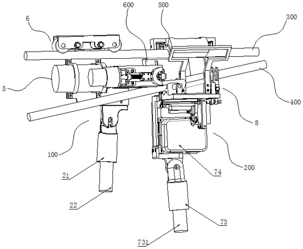
图1为本发明的结构示意图(左视方向);Fig. 1 is a structural representation of the present invention (direction seen from the left);
图2为本发明的结构示意图(正视方向);Fig. 2 is a structural representation of the present invention (front view direction);
图3为本发明的结构示意图(右视方向);Fig. 3 is the structural representation of the present invention (right direction);
图4为本发明的结构示意图(仰视方向);Fig. 4 is the structural representation (looking up direction) of the present invention;
图5为本发明的楔块夹持工具的结构示意图(正视方向);Fig. 5 is a structural schematic view (front view direction) of the wedge clamping tool of the present invention;
图6为本发明的楔块夹持工具的结构示意图(俯视方向);Fig. 6 is a schematic structural view (plan view direction) of the wedge clamping tool of the present invention;
图7为本发明的楔块夹持工具与楔块的安装示意图;Figure 7 is a schematic diagram of the installation of the wedge clamping tool and the wedge of the present invention;
图8为本发明的楔块夹持机架、楔块夹持机构、楔块打击机构的结构示意图(俯视方向);Fig. 8 is a structural schematic view (plan view direction) of the wedge clamping frame, the wedge clamping mechanism, and the wedge striking mechanism of the present invention;
图9为本发明的楔块夹持机架、对接锁紧结构、辅助对接装置的结构示意图(右视方向);Fig. 9 is a schematic view of the structure of the wedge clamping frame, the docking locking structure, and the auxiliary docking device (viewed from the right);
图10为本发明的C型块夹具体夹持工具的结构示意图(后视方向);Fig. 10 is a schematic structural view (rear view direction) of the clamping tool of the C-shaped block clamp body of the present invention;
图11为本发明的C型块夹具体夹持工具的结构示意图(后侧仰视方向);Fig. 11 is the structural representation of the clamping tool of the C-shaped block clamp body of the present invention (rear side looking up direction);
图12为本发明的C型块夹具体夹持工具的结构示意图(正视方向);Fig. 12 is a schematic structural view (front view direction) of the clamping tool of the C-shaped block clamp body of the present invention;
图13为图12中A处结构放大图;Figure 13 is an enlarged view of the structure at A in Figure 12;
图14为本发明的C型块夹具体夹持机架、C型块夹具体夹持上盖、拨杆卡合组件的结构示意图(正视方向);Fig. 14 is a structural schematic diagram (front view direction) of the clamping frame of the C-shaped block clamp body, the upper cover clamped by the C-shaped block clamp body, and the lever engaging assembly of the present invention;
图15为本发明的C型块夹具体夹持机架、C型块夹具体夹持上盖、拨杆卡合组件的结构分解图(正视方向);Fig. 15 is a structural exploded view (front view direction) of the clamping frame of the C-shaped block clamp body, the upper cover clamped by the C-shaped block clamp body, and the lever engaging assembly of the present invention;
图16为本发明的拨杆卡合组件的作用机理图。Fig. 16 is a working mechanism diagram of the shifting lever engaging assembly of the present invention.
具体实施方式Detailed ways
下面将结合本发明实施例中的附图,对本发明实施例中的技术方案进行清楚、完整地描述,显然,所描述的实施例仅仅是本发明一部分实施例,而不是全部的实施例。The following will clearly and completely describe the technical solutions in the embodiments of the present invention with reference to the accompanying drawings in the embodiments of the present invention. Obviously, the described embodiments are only some, not all, embodiments of the present invention.
参照图1-16,本发明提出的一种楔形弹性线夹分体对接式电动安装工具,包括楔块夹持工具100、C型块夹具体夹持工具200,而楔形弹性线夹由C型块夹具体500和楔块600组成。Referring to Figures 1-16, a wedge-shaped elastic wire clamp split butt joint electric installation tool proposed by the present invention includes a
楔块夹持工具100包括楔块夹持机架2,楔块夹持机架2下安装有楔块夹持支撑接头21,楔块夹持支撑接头21下安装有楔块夹持绝缘杆22。The
楔块夹持机架2内设置有楔块夹持机构4,楔块夹持机构4用于楔块600的夹持固定。A
其中,楔块夹持机构4包括П型夹持机架41,П型夹持机架41的两内侧壁内均设置有楔块弹性限位装置,楔块600两侧壁上均设置有竖直的楔块限位凹槽601,楔块600安装在П型夹持机架41内,且楔块弹性限位装置卡合在楔块限位凹槽601内。П型夹持机架41的两内侧壁内均设置有空腔,П型夹持机架41的内侧壁上设置有连通空腔的限位板伸缩孔,楔块弹性限位装置安装在空腔内;楔块弹性限位装置包括楔块限位板43、限位板连接杆44、限位板铰接销轴45,限位板连接杆44一端通过扭簧一铰接在限位板铰接销轴45上,楔块限位板43安装在限位板连接杆44另一端且楔块限位板43贯穿П型夹持机架41的内侧壁上的空腔并伸出至П型夹持机架41的内侧;楔块限位凹槽601的前侧内壁与楔块600的侧面相垂直,楔块限位凹槽601的后侧内壁为斜面。在实际使用时,楔块600能够自上而下卡入楔块夹持机构4的П型夹持机架41内,且楔块夹持机构4的两楔块限位板43分别卡入楔块600两侧的楔块限位凹槽601内。Wherein, the
楔块夹持机架2左右两侧均设置有对接锁紧结构3,对接锁紧结构3与C型块夹具体夹持机架7进行卡合,并实现楔块夹持工具100与C型块夹具体夹持工具200对接锁紧。The left and right sides of the
其中,对接锁紧结构3,包括对接锁紧电机31、旋转对接螺杆32、S型卡扣33、后顶进基座34、前顶进基座35,对接锁紧电机31安装在楔块夹持机架2侧端面上;旋转对接螺杆32后端安装在对接锁紧电机31的输出轴上,后顶进基座34、前顶进基座35安装在旋转对接螺杆32上,且后顶进基座34、前顶进基座35内设置的螺纹孔的内螺纹与旋转对接螺杆32上设置的外螺纹相干涉;S型卡扣33后端设置有S型卡扣安装孔37,S型卡扣33后端卡合在后顶进基座34与前顶进基座35之间,且旋转对接螺杆32贯穿在S型卡扣安装孔37中;后顶进基座34前端面、前顶进基座35的后端面均设置为弧形端面,且前顶进基座35后端面的弧形端面、后顶进基座34前端面的弧形端面分别与S型卡扣33后端前后端面相贴合;S型卡扣33末端前侧的楔块夹持机架2侧端面上设置有对接限位块36,S型卡扣33前侧的C型块夹具体夹持机架7上设置有锁紧销柱78,S型卡扣33前端与C型块夹具体夹持机架7上的锁紧销柱78实现卡合锁紧。在实际使用时,通过接锁紧电机31控制旋转对接螺杆32旋转,并利用后顶进基座34、前顶进基座35将二者之间设置的S型卡扣33向前顶进运动,当S型卡扣33末端与其前侧的对接限位块36实现接触后,S型卡扣33受对接限位块36阻挡后,S型卡扣33旋转且前端翘起;当S型卡扣33前端运动至C型块夹具体夹持机架7上的锁紧销柱78上方后,接锁紧电机31再控制旋转对接螺杆32旋转并控制后顶进基座34、前顶进基座35后移,使S型卡扣33前端落下并与锁紧销柱78实现卡合锁紧,从而完成楔块夹持工具100与C型块夹具体夹持工具200对接锁紧。同理,能够接锁紧电机31控制旋转对接螺杆32旋转,实现楔块夹持工具100与C型块夹具体夹持工具200的解锁分离。Among them, the
楔块夹持机架2上方设置有运动辅助机构6,其中,运动辅助机构6包括辅助对接支架61和辅助对接滚轮62,辅助对接支架61固定在楔块夹持机架2上,辅助对接滚轮62设置有若干个并安装在辅助对接支架61内,若干个辅助对接滚轮62安装高度相同且相互平行并安装在同一直线上。在实际使用时,将辅助对接装置6的辅助对接滚轮62挂在主线300上,便于维持楔块夹持工具100的稳定,然后将楔块夹持工具100整体向前移动并靠近C型块夹具体夹持工具200,并利于继下来利用对接锁紧结构3来实现楔块夹持工具100与C型块夹具体夹持工具200的对接锁紧。A motion auxiliary mechanism 6 is arranged above the
C型块夹具体夹持工具200包括C型块夹具体夹持机架7,C型块夹具体夹持机架7内设置有C型块夹具体安装区71并用于C型块夹具体500的安装。C型块夹具体夹持机架7下安装有C型块夹具体夹持支撑接头73,C型块夹具体夹持支撑接头73下安装有C型块夹具体夹持绝缘杆731。C型块夹具体夹持机架7内设置有锂电池组件74,锂电池组件74作为C型块夹具体夹持工具200中的各零部件工作的动力来源。The C-type block clamp
C型块夹具体夹持机架7前侧设置有支线固定机构8,在将C型块夹具体500安装入C型块夹持机架7的C型块夹具体安装区71内后,通过支线固定机构8能够将支线400卡合固定在C型块夹具体500的下沟槽内,便于后期的主线300与支线400的并线工作。The front side of the C-type
其中,支线固定机构8,包括支线固定调节螺杆81、支线固定控制电机82、以及两个固定卡爪装置,支线固定调节螺杆81通过轴承安装在C型块夹具体夹持机架7前侧端面上,并通过支线固定控制电机82控制旋转;固定卡爪装置,包括转动卡爪、圆形限位块86,转动卡爪由下端固定转动杆84、椭圆环85和上端弧形卡爪88组成并一体成型,下端固定转动杆84下端通过活动销轴固定在C型块夹具体夹持机架7前侧端面上,椭圆环85固定在下端固定转动杆84上端,上端弧形卡爪88安装在椭圆环85上端面;圆形限位块86安装在椭圆环85内侧的支线固定调节螺杆81上,椭圆环85两侧端面设置有贯穿其内部的调节螺杆孔851,支线固定调节螺杆81贯穿在调节螺杆孔851中;支线固定调节螺杆81上设置有对称的正向调节螺纹段811和逆向调节外螺纹段812,两个固定卡爪装置的圆形限位块86分别安装在正向调节螺纹段811和逆向调节外螺纹段812上,圆形限位块86内设置有限位块安装孔,两个圆形限位块86的限位块安装孔设置的外螺纹分别与支线固定调节螺杆81上的正向调节螺纹段811、逆向调节外螺纹段812干涉。支线固定调节螺杆81通过轴承安装在C型块夹具体夹持机架7前侧端面上,且支线固定调节螺杆81一端设置有从动大齿轮83,从动大齿轮83与支线固定控制电机82输出轴上安装的主动小齿轮相齿合。在实际工作时,支线固定控制电机82通过主动小齿轮与从动大齿轮83的齿合控制支线固定调节螺杆81的旋转,此时,正向调节螺纹段811、逆向调节外螺纹段812上的两圆形限位块86相向运动,从而控制两上端弧形卡爪88相向运动并将两上端弧形卡爪88之间的支线400进行固定,便于后期的主线300与支线400的并线工作。Among them, the branch
C型块夹具体安装区71上方一侧的C型块夹具体夹持机架7上设置有倾斜的主线导向支架72,利用倾斜的主线导向支架72,能够在C型块夹具体夹持工具200利用C型块夹具体夹持绝缘杆731上升过程中,便于主线300卡入C型块夹具体夹持工具200内安装的C型块夹具体500的上沟槽内,便于后期的主线300与支线400的并线工作。The C-type block clamp
楔块夹持机架2后侧设置有楔块打击机构5,楔块打击机构5用于击打楔块600并使其向前运动至C型块夹具体安装区71内安装的C型块夹具体500中,实现C型块夹具体500内的主线300与支线400的连接固定。The rear side of the
其中,楔块打击机构5包括楔块击打电机51、旋转顶进螺杆52、顶进滑块53、打击杆54,楔块夹持机架2上设置有打击机构顶进孔一22,旋转顶进螺杆52后端安装在楔块击打电机51的输出轴上,其前端贯穿打击机构顶进孔一22;楔块夹持机架2内两侧均设置有打击机构滑轨21,顶进滑块53两侧分别安装在打击机构滑轨21上滑动,打击杆54后端安装在顶进滑块53的前端面;顶进滑块53、打击杆54内部设置有带有干涉内螺纹的顶进干涉孔,旋转顶进螺杆52的前端设置在顶进干涉孔中,且旋转顶进螺杆52设置的外螺纹与顶进干涉孔的干涉内螺纹相干涉;П型夹持机架41的上端面设置有顶进贯穿孔42,打击杆54的前端贯穿于顶进贯穿孔42。在实际使用时,利用楔块击打电机51控制旋转顶进螺杆52旋转并实现打击杆54向前顶进,然后利用打击杆54即可将楔块600从楔块夹持机构4中顶出至C型块夹具体夹持工具200内的C型块夹具体500中的主线300与支线400之间,从而实现利用C型块夹具体500、楔块600完成主线300与支线400的并线工作。Wherein, the
C型块夹具体夹持机架7内的C型块夹具体安装区71上方设置有C型块夹具体夹持上盖75,C型块夹具体夹持上盖75通过C型块夹具体解锁机构9控制实现C型块夹持机架7内的C型块夹具体500的解锁,从而便于将C型块夹具体500、楔块600、主线300及支线400整体从C型块夹具体夹持工具200中脱离。The top of the C-type block clamp
其中,C型块夹具体解锁机构9包括U型铰接支架91、主拉杆一92、转盘94、舵机95、以及拨杆卡合组件1,C型块夹具体夹持机架7底部设置有支架铰接轴杆76,U型铰接支架91的两侧边杆的前端通过扭簧二铰接在支架铰接轴杆76上,转盘94、舵机95均安装在C型块夹具体夹持机架7内,且舵机95控制转盘94的旋转,U型铰接支架91的底杆上设置有延伸杆96,延伸杆96与转盘94之间设置有活动拉杆一93,活动拉杆一93一端通过销柱固定在转盘94端面非中心处,另一端通过销柱固定在延伸杆96上;主拉杆一92、以及拨杆卡合组件1均设置有两个分别安装在C型块夹具体夹持机架7的前后两侧,两个主拉杆一92下端均通过活动拉杆二97及销柱连接在U型铰接支架91的两侧边杆上,拨杆卡合组件1包括有固定卡板11、活动转板12、拨杆13,固定卡板11上设置有压杆活动卡孔111,固定卡板11安装在C型块夹具体夹持机架7上,活动转板12轴心处通过销柱安装在固定卡板11外侧,且活动转板12外周上设置有压杆卡合槽121和拨杆卡合槽122,C型块夹具体夹持上盖75通过上盖铰接轴杆77及扭簧三铰接在C型块夹具体夹持机架7上,C型块夹具体夹持上盖75内侧设置有压杆751,压杆751两端分别卡合在两个拨杆卡合组件1的压杆活动卡孔111和压杆卡合槽121内;拨杆13一端通过销柱固定在活动转板12下方的C型块夹具体夹持机架7端面,主拉杆一92上端通过活动拉杆三98及销柱连接在拨杆13另一端,且拨杆13另一端能够与活动转板12外周上的拨杆卡合槽122实现卡合。在实际工作时,C型块夹具体夹持上盖75向下合盖时,压杆751压制活动转板12进行旋转;同时U型铰接支架91在扭簧二的作用下,使主拉杆一92受到向上运动的力;当活动转板12旋转并使拨杆13另一端与活动转板12外周上的拨杆卡合槽122相卡合后即对活动转板12的旋转形成限位,C型块夹具体夹持上盖75合盖完成。当利用C型块夹具体500、楔块600完成主线300与支线400的并线工作后,通过舵机95控制转盘94旋转,再使主拉杆一92下拉,使拨杆13与活动转板12外周上的拨杆卡合槽122脱离,活动转板12回转,C型块夹具体夹持上盖75在扭簧三的作用下向上翻开,从而实现C型块夹具体500的解锁。Wherein, the C-shaped block clamp specific unlocking
本发明的一种楔形弹性线夹分体对接式电动安装工具,结构紧凑,能够在不停电的环境下,利用楔形弹性线夹实现架空电缆的并线工作,无需人工手动安装,自动化程度高,使用方便,安装效率高,安全可靠。A wedge-shaped elastic clamp split butt joint type electric installation tool of the present invention has a compact structure, and can use a wedge-shaped elastic clamp to realize parallel work of overhead cables without manual installation, and has a high degree of automation. Easy to use, high installation efficiency, safe and reliable.
以上所述,仅为本发明较佳的具体实施方式,但本发明的保护范围并不局限于此,任何熟悉本技术领域的技术人员在本发明揭露的技术范围内,根据本发明的技术方案及其发明构思加以等同替换或改变,都应涵盖在本发明的保护范围之内。The above is only a preferred embodiment of the present invention, but the scope of protection of the present invention is not limited thereto, any person familiar with the technical field within the technical scope disclosed in the present invention, according to the technical solution of the present invention Any equivalent replacement or change of the inventive concepts thereof shall fall within the protection scope of the present invention.
Claims (10)
Priority Applications (1)
| Application Number | Priority Date | Filing Date | Title |
|---|---|---|---|
| CN202210991584.8A CN115296103B (en) | 2022-08-18 | 2022-08-18 | A wedge-shaped elastic wire clamp split docking type electric installation tool |
Applications Claiming Priority (1)
| Application Number | Priority Date | Filing Date | Title |
|---|---|---|---|
| CN202210991584.8A CN115296103B (en) | 2022-08-18 | 2022-08-18 | A wedge-shaped elastic wire clamp split docking type electric installation tool |
Publications (2)
| Publication Number | Publication Date |
|---|---|
| CN115296103A true CN115296103A (en) | 2022-11-04 |
| CN115296103B CN115296103B (en) | 2025-03-07 |
Family
ID=83830558
Family Applications (1)
| Application Number | Title | Priority Date | Filing Date |
|---|---|---|---|
| CN202210991584.8A Active CN115296103B (en) | 2022-08-18 | 2022-08-18 | A wedge-shaped elastic wire clamp split docking type electric installation tool |
Country Status (1)
| Country | Link |
|---|---|
| CN (1) | CN115296103B (en) |
Cited By (2)
| Publication number | Priority date | Publication date | Assignee | Title |
|---|---|---|---|---|
| CN115603140A (en) * | 2022-11-07 | 2023-01-13 | 合肥工业大学(Cn) | An intelligent installation equipment for cylindrical lead clips |
| CN119070539A (en) * | 2024-11-04 | 2024-12-03 | 国网安徽省电力有限公司怀远县供电公司 | A gear-adjusting motor mounting and docking mechanism |
Citations (4)
| Publication number | Priority date | Publication date | Assignee | Title |
|---|---|---|---|---|
| CN113675626A (en) * | 2021-08-09 | 2021-11-19 | 国网安徽省电力有限公司电力科学研究院 | Wedge type lead clip |
| CN114284766A (en) * | 2022-01-13 | 2022-04-05 | 国网安徽省电力有限公司电力科学研究院 | Electrified device that connects sparks of integral type parallel groove clamp |
| WO2022067873A1 (en) * | 2020-09-29 | 2022-04-07 | 垒途智能教科技术研究院江苏有限公司 | Repairing system for new energy automobile motor |
| CN114361908A (en) * | 2022-01-13 | 2022-04-15 | 合肥工业大学 | Parallel groove clamp live-line installation tool |
-
2022
- 2022-08-18 CN CN202210991584.8A patent/CN115296103B/en active Active
Patent Citations (4)
| Publication number | Priority date | Publication date | Assignee | Title |
|---|---|---|---|---|
| WO2022067873A1 (en) * | 2020-09-29 | 2022-04-07 | 垒途智能教科技术研究院江苏有限公司 | Repairing system for new energy automobile motor |
| CN113675626A (en) * | 2021-08-09 | 2021-11-19 | 国网安徽省电力有限公司电力科学研究院 | Wedge type lead clip |
| CN114284766A (en) * | 2022-01-13 | 2022-04-05 | 国网安徽省电力有限公司电力科学研究院 | Electrified device that connects sparks of integral type parallel groove clamp |
| CN114361908A (en) * | 2022-01-13 | 2022-04-15 | 合肥工业大学 | Parallel groove clamp live-line installation tool |
Cited By (4)
| Publication number | Priority date | Publication date | Assignee | Title |
|---|---|---|---|---|
| CN115603140A (en) * | 2022-11-07 | 2023-01-13 | 合肥工业大学(Cn) | An intelligent installation equipment for cylindrical lead clips |
| CN115603140B (en) * | 2022-11-07 | 2025-09-05 | 合肥工业大学 | Intelligent installation equipment for cylindrical lead wire clamps |
| CN119070539A (en) * | 2024-11-04 | 2024-12-03 | 国网安徽省电力有限公司怀远县供电公司 | A gear-adjusting motor mounting and docking mechanism |
| CN119070539B (en) * | 2024-11-04 | 2024-12-31 | 国网安徽省电力有限公司怀远县供电公司 | A gear-adjusting motor mounting and docking mechanism |
Also Published As
| Publication number | Publication date |
|---|---|
| CN115296103B (en) | 2025-03-07 |
Similar Documents
| Publication | Publication Date | Title |
|---|---|---|
| CN205151185U (en) | Flexible centre gripping clamping jaw of liquid crystal display panel and liquid crystal display panel grasping system | |
| CN212043360U (en) | Pipeline strutting arrangement is used in pipeline welding | |
| CN211477844U (en) | Tensile test fixture with adjustable tensile angle | |
| WO2022135314A1 (en) | Climbing device for use in mural maintenance | |
| CN115296103B (en) | A wedge-shaped elastic wire clamp split docking type electric installation tool | |
| CN114473467A (en) | Transmission part forming, assembling and splicing method | |
| CN217394412U (en) | A self-centering positioning clamping mechanism | |
| CN208391214U (en) | A kind of chamfering clamp of milling machine processing | |
| CN218994957U (en) | Auxiliary equipment for testing textile strength | |
| CN218503933U (en) | Clamping tool suitable for machining parts in different shapes | |
| CN220671125U (en) | Clamp for stretching building materials | |
| CN215201885U (en) | A high-precision fixture for the detection of waterproof materials in construction engineering | |
| CN214685303U (en) | Journal stirrup hole processingequipment | |
| CN215788327U (en) | Machining clamp with multi-directional fixing function for precision machining | |
| CN223422158U (en) | Elevator door limiting device | |
| CN115127503A (en) | Aperture detection device and detection method for positioning through hole | |
| CN209166816U (en) | A kind of impulse bearing seat load test device | |
| CN220244707U (en) | High-stability pushing mechanism | |
| CN224049510U (en) | Flowering pin convenient for fixing and clamping | |
| CN113805367A (en) | Etching frame automatic locking device for mounting etching machine | |
| CN217255714U (en) | Turnover plate displacement clamp for building construction | |
| CN219403014U (en) | An automobile welding jig with cushioning function | |
| CN220921419U (en) | Auxiliary welding device for pipe fittings | |
| CN223476643U (en) | A steel structure connection device for steel structure engineering | |
| CN218917016U (en) | Novel extrusion needling test machine |
Legal Events
| Date | Code | Title | Description |
|---|---|---|---|
| PB01 | Publication | ||
| PB01 | Publication | ||
| SE01 | Entry into force of request for substantive examination | ||
| SE01 | Entry into force of request for substantive examination | ||
| GR01 | Patent grant | ||
| GR01 | Patent grant |