CN115285829A - Auxiliary crane for cabin cover of offshore wind turbine - Google Patents
Auxiliary crane for cabin cover of offshore wind turbine Download PDFInfo
- Publication number
- CN115285829A CN115285829A CN202111663751.8A CN202111663751A CN115285829A CN 115285829 A CN115285829 A CN 115285829A CN 202111663751 A CN202111663751 A CN 202111663751A CN 115285829 A CN115285829 A CN 115285829A
- Authority
- CN
- China
- Prior art keywords
- plate
- limit
- sliding plate
- cabin cover
- driving
- Prior art date
- Legal status (The legal status is an assumption and is not a legal conclusion. Google has not performed a legal analysis and makes no representation as to the accuracy of the status listed.)
- Withdrawn
Links
- 230000007246 mechanism Effects 0.000 claims abstract description 20
- 229910000831 Steel Inorganic materials 0.000 claims description 17
- 239000010959 steel Substances 0.000 claims description 17
- 238000009434 installation Methods 0.000 claims description 15
- 230000000712 assembly Effects 0.000 claims description 6
- 238000000429 assembly Methods 0.000 claims description 6
- 230000000903 blocking effect Effects 0.000 claims 1
- 230000000694 effects Effects 0.000 claims 1
- 239000000725 suspension Substances 0.000 claims 1
- 238000000034 method Methods 0.000 description 6
- 230000008569 process Effects 0.000 description 4
- 230000009471 action Effects 0.000 description 3
- 238000010586 diagram Methods 0.000 description 3
- 230000007547 defect Effects 0.000 description 1
- 230000001681 protective effect Effects 0.000 description 1
Images



Classifications
-
- B—PERFORMING OPERATIONS; TRANSPORTING
- B66—HOISTING; LIFTING; HAULING
- B66C—CRANES; LOAD-ENGAGING ELEMENTS OR DEVICES FOR CRANES, CAPSTANS, WINCHES, OR TACKLES
- B66C1/00—Load-engaging elements or devices attached to lifting or lowering gear of cranes or adapted for connection therewith for transmitting lifting forces to articles or groups of articles
- B66C1/10—Load-engaging elements or devices attached to lifting or lowering gear of cranes or adapted for connection therewith for transmitting lifting forces to articles or groups of articles by mechanical means
- B66C1/12—Slings comprising chains, wires, ropes, or bands; Nets
- B66C1/16—Slings with load-engaging platforms or frameworks
-
- B—PERFORMING OPERATIONS; TRANSPORTING
- B66—HOISTING; LIFTING; HAULING
- B66C—CRANES; LOAD-ENGAGING ELEMENTS OR DEVICES FOR CRANES, CAPSTANS, WINCHES, OR TACKLES
- B66C1/00—Load-engaging elements or devices attached to lifting or lowering gear of cranes or adapted for connection therewith for transmitting lifting forces to articles or groups of articles
- B66C1/10—Load-engaging elements or devices attached to lifting or lowering gear of cranes or adapted for connection therewith for transmitting lifting forces to articles or groups of articles by mechanical means
- B66C1/62—Load-engaging elements or devices attached to lifting or lowering gear of cranes or adapted for connection therewith for transmitting lifting forces to articles or groups of articles by mechanical means comprising article-engaging members of a shape complementary to that of the articles to be handled
-
- B—PERFORMING OPERATIONS; TRANSPORTING
- B66—HOISTING; LIFTING; HAULING
- B66C—CRANES; LOAD-ENGAGING ELEMENTS OR DEVICES FOR CRANES, CAPSTANS, WINCHES, OR TACKLES
- B66C13/00—Other constructional features or details
- B66C13/04—Auxiliary devices for controlling movements of suspended loads, or preventing cable slack
- B66C13/06—Auxiliary devices for controlling movements of suspended loads, or preventing cable slack for minimising or preventing longitudinal or transverse swinging of loads
-
- B—PERFORMING OPERATIONS; TRANSPORTING
- B66—HOISTING; LIFTING; HAULING
- B66C—CRANES; LOAD-ENGAGING ELEMENTS OR DEVICES FOR CRANES, CAPSTANS, WINCHES, OR TACKLES
- B66C13/00—Other constructional features or details
- B66C13/04—Auxiliary devices for controlling movements of suspended loads, or preventing cable slack
- B66C13/08—Auxiliary devices for controlling movements of suspended loads, or preventing cable slack for depositing loads in desired attitudes or positions
-
- Y—GENERAL TAGGING OF NEW TECHNOLOGICAL DEVELOPMENTS; GENERAL TAGGING OF CROSS-SECTIONAL TECHNOLOGIES SPANNING OVER SEVERAL SECTIONS OF THE IPC; TECHNICAL SUBJECTS COVERED BY FORMER USPC CROSS-REFERENCE ART COLLECTIONS [XRACs] AND DIGESTS
- Y02—TECHNOLOGIES OR APPLICATIONS FOR MITIGATION OR ADAPTATION AGAINST CLIMATE CHANGE
- Y02E—REDUCTION OF GREENHOUSE GAS [GHG] EMISSIONS, RELATED TO ENERGY GENERATION, TRANSMISSION OR DISTRIBUTION
- Y02E10/00—Energy generation through renewable energy sources
- Y02E10/70—Wind energy
- Y02E10/72—Wind turbines with rotation axis in wind direction
Landscapes
- Engineering & Computer Science (AREA)
- Mechanical Engineering (AREA)
- Jib Cranes (AREA)
Abstract
Description
技术领域technical field
本发明涉及吊机的技术领域,具体涉及一种海上风力发电机舱罩辅助吊机。The invention relates to the technical field of cranes, in particular to an auxiliary crane for a nacelle cover of an offshore wind power generator.
背景技术Background technique
海上风力发电机舱罩作为海上风力发电机组的重要部件,是海上风力发电机组的防护结构,使海上风力发电机组能在海上恶劣的气象环境中正常工作,海上风力发电机舱罩在安装时需要通过吊机将海上风力发电机舱罩起吊中海上的安装柱上,在起吊前需要对海上风力发电机舱罩进行限位,避免在起吊时海上风力发电机舱罩随意晃动造成危险,但是现有的吊机在对海上风力发电机舱罩进行限位时,操作过程较为复杂,海上风力发电机舱罩的安装效率较低。Offshore wind turbine nacelle, as an important part of the offshore wind turbine, is the protective structure of the offshore wind turbine, so that the offshore wind turbine can work normally in the harsh weather environment at sea. The machine lifts the offshore wind turbine cabin cover on the installation column in the sea. Before lifting, it is necessary to limit the position of the offshore wind turbine cabin cover to avoid the danger caused by the random shaking of the offshore wind turbine cabin cover during lifting. However, the existing cranes are When limiting the position of the offshore wind turbine nacelle, the operation process is relatively complicated, and the installation efficiency of the offshore wind turbine nacelle is low.
发明内容Contents of the invention
本发明的目的在于提供一种海上风力发电机舱罩辅助吊机,以克服现有技术中的上述缺陷。The object of the present invention is to provide an auxiliary crane for the nacelle of an offshore wind power generator to overcome the above-mentioned defects in the prior art.
一种海上风力发电机舱罩辅助吊机,包括吊机主体、托板、定位柱及限位机构,所述吊机主体的起吊绳上设有吊装件,所述吊装件的左右两侧和下部分别设有吊钩,所述托板的左右两侧对称设有侧位钢丝绳,两个侧位钢丝绳的上端分别套设于吊装件左右两侧的吊钩上,所述定位柱固定于托板上并用于插接于发电机舱罩的安装孔中,所述限位机构设于定位柱上,限位机构上设有套设于吊装件下部吊钩的中间钢丝绳,限位机构在中间钢丝绳的作用下对发电机舱罩内部进行阻挡限位。An auxiliary crane for the cabin cover of an offshore wind power generator, including a crane main body, a supporting plate, a positioning column and a limit mechanism. The lifting rope of the crane main body is provided with a hoisting piece, and the left and right sides and the lower part of the hoisting piece are Hooks are respectively provided, side steel wire ropes are symmetrically provided on the left and right sides of the supporting plate, the upper ends of the two side steel wire ropes are respectively sleeved on the hooks on the left and right sides of the lifting piece, and the positioning column is fixed on the supporting plate and used to be plugged into the installation hole of the generator cabin cover. The limit mechanism is set on the positioning column. The limit mechanism is provided with an intermediate wire rope that is sleeved on the lower hook of the hoisting piece. The limit mechanism is located on the center wire rope Under the action, the interior of the generator cabin cover is blocked and limited.
优选的,所述限位机构包括限位筒、滑动盘、弹簧、驱动组件及下压组件,所述限位筒固定于定位柱上且其顶部固定有盖板,滑动盘滑动连接于限位筒中的导向杆上,所述弹簧套设于导向杆上并位于滑动盘与限位筒的底部之间,所述滑动盘的下方设有若干用于驱动滑动盘下移的所述驱动组件,沿限位筒的圆周均布有若干所述下压组件,滑动盘在导向杆上移动时驱动下压组件转动对发电机舱罩内部进行下压。Preferably, the limiting mechanism includes a limiting cylinder, a sliding plate, a spring, a driving component and a pressing component, the limiting cylinder is fixed on the positioning column and a cover plate is fixed on the top thereof, and the sliding plate is slidably connected to the limiting cylinder. On the guide rod in the cylinder, the spring is sleeved on the guide rod and is located between the sliding plate and the bottom of the limit cylinder. There are several driving components for driving the sliding plate to move down under the sliding plate. A plurality of said pressing assemblies are evenly distributed along the circumference of the limiting cylinder, and when the sliding plate moves on the guide rod, the pressing assemblies are driven to rotate to press down the inside of the generator cabin cover.
优选的,所述驱动组件包括滚轮一、滚轮二、驱动钢绳及连接盘,所述滑动盘的下方设有与限位筒底部转动连接的所述滚轮一,所述滚轮二转动连接于限位筒外侧的定位柱上,所述驱动钢绳的一端与滑动盘的底部连接,另一端经滚轮一及滚轮二后与限位筒上方的所述连接盘连接,所述中间钢丝绳的下端与连接盘固定Preferably, the driving assembly includes roller one, roller two, a driving steel rope and a connecting plate, the roller one is rotatably connected to the bottom of the limiting cylinder provided under the sliding plate, and the second roller is rotatably connected to the limiting cylinder. On the positioning post on the outside of the positioning cylinder, one end of the driving steel rope is connected to the bottom of the sliding plate, and the other end is connected to the connecting plate above the limit cylinder after the other end passes through the first roller and the second roller. Connection plate fixed
优选的,所述下压组件包括压板及驱动板,所述压板的一端与定位柱上的安装槽内壁通过销轴铰接,另一端伸出至定位柱外,所述驱动板的一端与滑动盘通过销轴铰接,另一端与压板的上端通过销轴铰接。Preferably, the pressing assembly includes a pressing plate and a driving plate, one end of the pressing plate is hinged to the inner wall of the installation groove on the positioning column through a pin shaft, and the other end protrudes out of the positioning column, and one end of the driving plate is connected to the sliding plate It is hinged by a pin shaft, and the other end is hinged with the upper end of the pressing plate by a pin shaft.
优选的,所述压板的底部均设有橡胶垫。Preferably, rubber pads are provided on the bottoms of the pressing plates.
本发明具有如下优点:The present invention has the following advantages:
本发明在使用时,通过设置限位机构,定位柱插入发电机舱罩的安装孔中,被通过托板两侧的侧位钢丝绳对发电机舱罩的左右两侧进行限位,当中间钢丝绳套设在吊钩上被拉直时,会通过驱动钢绳带动滑动盘下移,在滑动盘下移时会通过驱动板带动压板压向发电机舱罩,自动对发电机舱罩进行限位,简化了对发电机舱罩限位过程,提高发电机舱罩的安装效率。When the present invention is in use, by setting a limit mechanism, the positioning column is inserted into the installation hole of the generator cabin cover, and the left and right sides of the generator cabin cover are limited by the side wire ropes on both sides of the supporting plate. When being straightened on the hook, the driving steel rope will drive the sliding plate to move down, and when the sliding plate moves down, the driving plate will drive the pressure plate to press against the generator cabin cover, and the generator cabin cover will be automatically limited, which simplifies the installation The limit process of the generator cabin cover improves the installation efficiency of the generator cabin cover.
附图说明Description of drawings
图1为本发明整体三维的结构示意图。Fig. 1 is a schematic diagram of the overall three-dimensional structure of the present invention.
图2为本发明安装发电机舱罩时的结构示意图。Fig. 2 is a structural schematic view of the present invention when the generator cabin cover is installed.
图3为本发明托板、定位柱及限位机构的结构示意图。Fig. 3 is a structural schematic diagram of the pallet, the positioning column and the limiting mechanism of the present invention.
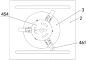
图4为图3的俯视图。FIG. 4 is a top view of FIG. 3 .
图5为图3未安装限位筒及盖板时的结构示意图。Fig. 5 is a schematic diagram of the structure of Fig. 3 when the limit cylinder and the cover plate are not installed.
其中:1、吊机主体,11、起吊绳,12、吊装件,13、吊钩,2、托板,21、侧位钢丝绳,3、定位柱,4、限位机构,41、限位筒,411、盖板,42、滑动盘,43、导向杆,44、弹簧,45、驱动组件,451、滚轮一,452、滚轮二,453、驱动钢绳,454、连接盘,46、下压组件,461、压板,462、驱动板,463、橡胶垫,5、中间钢丝绳,6、发电机舱罩。Among them: 1. Crane main body, 11. Hoisting rope, 12. Hoisting parts, 13. Hook, 2. Support plate, 21. Side wire rope, 3. Positioning column, 4. Limiting mechanism, 41. Limiting cylinder , 411, cover plate, 42, sliding plate, 43, guide rod, 44, spring, 45, driving assembly, 451, roller one, 452, roller two, 453, driving steel rope, 454, connecting plate, 46, pressing down Components, 461, pressing plate, 462, drive plate, 463, rubber pad, 5, middle wire rope, 6, generator cabin cover.
具体实施方式Detailed ways
下面对照附图,通过对实施例的描述,对本发明具体实施方式作进一步详细的说明,以帮助本领域的技术人员对本发明的构思、技术方案有更完整、准确和深入的理解。The specific implementation of the present invention will be described in further detail below by describing the embodiments with reference to the accompanying drawings, so as to help those skilled in the art have a more complete, accurate and in-depth understanding of the concept and technical solutions of the present invention.
如图1-5所示,本发明提供了一种海上风力发电机舱罩辅助吊机,包括吊机主体1、托板2、定位柱3及限位机构4,所述吊机主体1的起吊绳11上设有吊装件12,所述吊装件12的左右两侧和下部分别设有吊钩13,所述托板2的左右两侧对称设有侧位钢丝绳21,两个侧位钢丝绳21的上端分别套设于吊装件12左右两侧的吊钩13上,所述定位柱3固定于托板2上并用于插接于发电机舱罩6的安装孔中,所述限位机构4设于定位柱3上,限位机构4上设有套设于吊装件12下部吊钩13的中间钢丝绳5,限位机构4在中间钢丝绳5的作用下对发电机舱罩6内部进行阻挡限位。As shown in Figures 1-5, the present invention provides an auxiliary crane for the nacelle of an offshore wind power generator, including a crane main body 1, a supporting
需要注意的是,所述限位机构4包括限位筒41、滑动盘42、弹簧44、驱动组件45及下压组件46,所述限位筒41固定于定位柱3上且其顶部固定有盖板411,滑动盘42滑动连接于限位筒41中的导向杆43上,所述弹簧44套设于导向杆43上并位于滑动盘42与限位筒41的底部之间,所述滑动盘42的下方设有若干用于驱动滑动盘42下移的所述驱动组件45,沿限位筒41的圆周均布有若干所述下压组件46,滑动盘42在导向杆43上移动时驱动下压组件46转动对发电机舱罩6内部进行下压。It should be noted that the
此外,所述驱动组件45包括滚轮一451、滚轮二452、驱动钢绳453及连接盘454,所述滑动盘42的下方设有与限位筒41底部转动连接的所述滚轮一451,所述滚轮二452转动连接于限位筒41外侧的定位柱3上,所述驱动钢绳453的一端与滑动盘42的底部连接,另一端经滚轮一451及滚轮二452后与限位筒41上方的所述连接盘454连接,所述中间钢丝绳5的下端与连接盘454固定In addition, the
另外,所述下压组件46包括压板461及驱动板462,所述压板461的一端与定位柱3上的安装槽内壁通过销轴铰接,另一端伸出至定位柱3外,所述驱动板462的一端与滑动盘42通过销轴铰接,另一端与压板461的上端通过销轴铰接,压板461的底部均设有橡胶垫463。In addition, the
具体实施方式及原理:Specific implementation and principle:
在对工厂内生产好的发电机舱罩6进行转移时,将托板2先放置于转移车辆上,再通过工厂内的龙门吊将发电机舱罩6吊至托板2处并使托板2上的定位柱3插入发电机舱罩6的安装孔中,由于中间钢丝绳5未被拉直,滑动盘42在导向杆43上弹簧44弹力的作用下,滑动盘42与限位筒41顶部的盖板411内壁保持接触,同时驱动板463带动压板461转动使压板461旋转至靠近限位筒41,从而使定位柱3能够顺利插入发电机舱罩6的安装孔中,转移车辆将发电机舱罩6转运至待安装处,将托板2两侧的侧位钢丝绳21套设在吊机主体1的吊装件12左右两侧的吊钩13上,并将中间钢丝绳5套设在吊装件12下端的吊钩13上,在中间钢丝绳5被拉直的过程中会带动连接盘454上移,在连接盘454上移时,会通过驱动钢绳453带动滑动盘42向下移动,滑动盘42在向下移动的过程中通过驱动板462带动压板461朝向发电机舱罩6转动,当中间钢丝绳5被完全拉直时,此时压板461与导向杆43处于垂直状态,发电机舱罩6位于压板462与托板2之间,从而对发电机舱罩6进行限位,工人操作吊机主体1将发电机舱罩6吊至海上的发电机舱罩安装柱上。When transferring the
综上所述,本发明在使用时通过设置限位机构4,定位柱3插入发电机舱罩6的安装孔中,被通过托板2两侧的侧位钢丝绳21对发电机舱罩6的左右两侧进行限位,当中间钢丝绳5套设在吊钩13上被拉直时,会通过驱动钢绳453带动滑动盘42下移,在滑动盘42下移时会通过驱动板462带动压板461压向发电机舱罩6,自动对发电机舱罩6进行限位,简化了对发电机舱罩6限位过程,提高发电机舱罩6的安装效率。In summary, when the present invention is in use, by setting the
上面结合附图对本发明进行了示例性描述,显然本发明具体实现并不受上述方式的限制,只要采用了本发明的构思和技术方案进行的各种非实质性的改进,或未经改进将本实用发明和技术方案直接应用于其它场合的,均在本发明保护范围之内。The present invention has been exemplarily described above in conjunction with the accompanying drawings. Obviously, the specific implementation of the present invention is not limited by the above methods, as long as various insubstantial improvements are made using the concept and technical solutions of the present invention, or the present invention will be If the utility invention and technical solutions are directly applied to other occasions, they all fall within the protection scope of the present invention.
Claims (5)
Priority Applications (1)
| Application Number | Priority Date | Filing Date | Title |
|---|---|---|---|
| CN202111663751.8A CN115285829A (en) | 2021-12-30 | 2021-12-30 | Auxiliary crane for cabin cover of offshore wind turbine |
Applications Claiming Priority (1)
| Application Number | Priority Date | Filing Date | Title |
|---|---|---|---|
| CN202111663751.8A CN115285829A (en) | 2021-12-30 | 2021-12-30 | Auxiliary crane for cabin cover of offshore wind turbine |
Publications (1)
| Publication Number | Publication Date |
|---|---|
| CN115285829A true CN115285829A (en) | 2022-11-04 |
Family
ID=83819185
Family Applications (1)
| Application Number | Title | Priority Date | Filing Date |
|---|---|---|---|
| CN202111663751.8A Withdrawn CN115285829A (en) | 2021-12-30 | 2021-12-30 | Auxiliary crane for cabin cover of offshore wind turbine |
Country Status (1)
| Country | Link |
|---|---|
| CN (1) | CN115285829A (en) |
Cited By (1)
| Publication number | Priority date | Publication date | Assignee | Title |
|---|---|---|---|---|
| CN118058562A (en) * | 2024-04-18 | 2024-05-24 | 卓道(泉州)鞋材有限公司 | An electric code printer for labor protection shoes processing |
-
2021
- 2021-12-30 CN CN202111663751.8A patent/CN115285829A/en not_active Withdrawn
Cited By (2)
| Publication number | Priority date | Publication date | Assignee | Title |
|---|---|---|---|---|
| CN118058562A (en) * | 2024-04-18 | 2024-05-24 | 卓道(泉州)鞋材有限公司 | An electric code printer for labor protection shoes processing |
| CN118058562B (en) * | 2024-04-18 | 2024-07-09 | 卓道(泉州)鞋材有限公司 | Electronic ink recorder is used in processing of labour protection shoes of being convenient for |
Similar Documents
| Publication | Publication Date | Title |
|---|---|---|
| CN103303807A (en) | Self-lifting type crane for wind generating set | |
| CN115367677B (en) | Wind power tower construction platform and method | |
| CN204422347U (en) | A kind of missile wing static loading test device | |
| CN204848017U (en) | Swing crane; derrick | |
| CN212611888U (en) | A two-dimensional positioning device for steel box girder installation and a steel box girder hoisting system | |
| CN106768587A (en) | Device and method for testing static braking force of low-speed shaft brake energy efficiency test | |
| CN220866943U (en) | Crane with anti-swing device | |
| CN219444813U (en) | Maintenance supporting device for petroleum drilling diesel engine | |
| CN215828264U (en) | Lifting device for installation of waste gas treatment system | |
| CN102505587A (en) | Special steel rail hoisting device for railway classification yard | |
| CN215208185U (en) | Wind driven generator tower cylinder hoisting elevator | |
| CN205772880U (en) | A kind of hanging balancing formula hoist crab | |
| CN218114734U (en) | Safety protection device for hoisting machinery | |
| CN209689934U (en) | A kind of automobile engine cover lifting structure | |
| CN204778587U (en) | A synchronous lifting tool and lifting device | |
| CN203359928U (en) | Lifting mechanism of wind electricity maintaining detecting device | |
| CN202754722U (en) | Novel rotating disc type crane car mechanism | |
| CN108163739B (en) | Marine hoisting apparatus of ocean engineering | |
| CN215946560U (en) | Aerogenerator main shaft upset lifting device | |
| CN204265314U (en) | Two-wheel rotary crane | |
| CN223722612U (en) | Protective device for hoisting crane | |
| CN221625766U (en) | Climbing mechanism for double-drive gantry debugging | |
| CN216332609U (en) | Self-adaptive convenient channel for operation deck and jacket platform | |
| CN218968596U (en) | Curtain wall material hoisting mechanism | |
| CN217377123U (en) | Rotating crane for hydropower station |
Legal Events
| Date | Code | Title | Description |
|---|---|---|---|
| PB01 | Publication | ||
| PB01 | Publication | ||
| SE01 | Entry into force of request for substantive examination | ||
| SE01 | Entry into force of request for substantive examination | ||
| WW01 | Invention patent application withdrawn after publication | ||
| WW01 | Invention patent application withdrawn after publication |
Application publication date: 20221104 |