CN115284123A - Polyurethane board feeding system and working method - Google Patents
Polyurethane board feeding system and working method Download PDFInfo
- Publication number
- CN115284123A CN115284123A CN202211196273.9A CN202211196273A CN115284123A CN 115284123 A CN115284123 A CN 115284123A CN 202211196273 A CN202211196273 A CN 202211196273A CN 115284123 A CN115284123 A CN 115284123A
- Authority
- CN
- China
- Prior art keywords
- strip
- driving
- sleeve
- hole
- groove
- Prior art date
- Legal status (The legal status is an assumption and is not a legal conclusion. Google has not performed a legal analysis and makes no representation as to the accuracy of the status listed.)
- Pending
Links
- 229920002635 polyurethane Polymers 0.000 title claims abstract description 23
- 239000004814 polyurethane Substances 0.000 title claims abstract description 23
- 238000000034 method Methods 0.000 title claims abstract description 15
- 238000001514 detection method Methods 0.000 claims abstract description 55
- 238000004080 punching Methods 0.000 claims abstract description 26
- 239000007788 liquid Substances 0.000 claims description 44
- 238000005498 polishing Methods 0.000 claims description 33
- 230000007246 mechanism Effects 0.000 claims description 32
- 238000005507 spraying Methods 0.000 claims description 29
- 238000003860 storage Methods 0.000 claims description 13
- 238000005520 cutting process Methods 0.000 claims description 8
- 238000013459 approach Methods 0.000 claims description 6
- 230000008569 process Effects 0.000 claims description 4
- 230000002159 abnormal effect Effects 0.000 claims description 3
- 238000001125 extrusion Methods 0.000 claims description 2
- 238000004891 communication Methods 0.000 description 4
- 230000008878 coupling Effects 0.000 description 3
- 238000010168 coupling process Methods 0.000 description 3
- 238000005859 coupling reaction Methods 0.000 description 3
- 230000000694 effects Effects 0.000 description 3
- 239000012535 impurity Substances 0.000 description 3
- 239000000463 material Substances 0.000 description 3
- 239000007921 spray Substances 0.000 description 3
- 230000000903 blocking effect Effects 0.000 description 1
- 238000010586 diagram Methods 0.000 description 1
- 238000011010 flushing procedure Methods 0.000 description 1
- 230000006872 improvement Effects 0.000 description 1
- 238000009434 installation Methods 0.000 description 1
- 238000011900 installation process Methods 0.000 description 1
- 238000004519 manufacturing process Methods 0.000 description 1
- 238000012986 modification Methods 0.000 description 1
- 230000004048 modification Effects 0.000 description 1
- 238000012545 processing Methods 0.000 description 1
Images



Classifications
-
- B—PERFORMING OPERATIONS; TRANSPORTING
- B24—GRINDING; POLISHING
- B24B—MACHINES, DEVICES, OR PROCESSES FOR GRINDING OR POLISHING; DRESSING OR CONDITIONING OF ABRADING SURFACES; FEEDING OF GRINDING, POLISHING, OR LAPPING AGENTS
- B24B9/00—Machines or devices designed for grinding edges or bevels on work or for removing burrs; Accessories therefor
- B24B9/02—Machines or devices designed for grinding edges or bevels on work or for removing burrs; Accessories therefor characterised by a special design with respect to properties of materials specific to articles to be ground
- B24B9/20—Machines or devices designed for grinding edges or bevels on work or for removing burrs; Accessories therefor characterised by a special design with respect to properties of materials specific to articles to be ground of plastics
-
- B—PERFORMING OPERATIONS; TRANSPORTING
- B21—MECHANICAL METAL-WORKING WITHOUT ESSENTIALLY REMOVING MATERIAL; PUNCHING METAL
- B21D—WORKING OR PROCESSING OF SHEET METAL OR METAL TUBES, RODS OR PROFILES WITHOUT ESSENTIALLY REMOVING MATERIAL; PUNCHING METAL
- B21D19/00—Flanging or other edge treatment, e.g. of tubes
- B21D19/005—Edge deburring or smoothing
-
- B—PERFORMING OPERATIONS; TRANSPORTING
- B21—MECHANICAL METAL-WORKING WITHOUT ESSENTIALLY REMOVING MATERIAL; PUNCHING METAL
- B21D—WORKING OR PROCESSING OF SHEET METAL OR METAL TUBES, RODS OR PROFILES WITHOUT ESSENTIALLY REMOVING MATERIAL; PUNCHING METAL
- B21D28/00—Shaping by press-cutting; Perforating
- B21D28/24—Perforating, i.e. punching holes
- B21D28/26—Perforating, i.e. punching holes in sheets or flat parts
-
- B—PERFORMING OPERATIONS; TRANSPORTING
- B24—GRINDING; POLISHING
- B24B—MACHINES, DEVICES, OR PROCESSES FOR GRINDING OR POLISHING; DRESSING OR CONDITIONING OF ABRADING SURFACES; FEEDING OF GRINDING, POLISHING, OR LAPPING AGENTS
- B24B41/00—Component parts such as frames, beds, carriages, headstocks
- B24B41/005—Feeding or manipulating devices specially adapted to grinding machines
-
- B—PERFORMING OPERATIONS; TRANSPORTING
- B24—GRINDING; POLISHING
- B24B—MACHINES, DEVICES, OR PROCESSES FOR GRINDING OR POLISHING; DRESSING OR CONDITIONING OF ABRADING SURFACES; FEEDING OF GRINDING, POLISHING, OR LAPPING AGENTS
- B24B49/00—Measuring or gauging equipment for controlling the feed movement of the grinding tool or work; Arrangements of indicating or measuring equipment, e.g. for indicating the start of the grinding operation
- B24B49/02—Measuring or gauging equipment for controlling the feed movement of the grinding tool or work; Arrangements of indicating or measuring equipment, e.g. for indicating the start of the grinding operation according to the instantaneous size and required size of the workpiece acted upon, the measuring or gauging being continuous or intermittent
-
- B—PERFORMING OPERATIONS; TRANSPORTING
- B24—GRINDING; POLISHING
- B24B—MACHINES, DEVICES, OR PROCESSES FOR GRINDING OR POLISHING; DRESSING OR CONDITIONING OF ABRADING SURFACES; FEEDING OF GRINDING, POLISHING, OR LAPPING AGENTS
- B24B5/00—Machines or devices designed for grinding surfaces of revolution on work, including those which also grind adjacent plane surfaces; Accessories therefor
- B24B5/35—Accessories
- B24B5/355—Feeding means
-
- B—PERFORMING OPERATIONS; TRANSPORTING
- B24—GRINDING; POLISHING
- B24B—MACHINES, DEVICES, OR PROCESSES FOR GRINDING OR POLISHING; DRESSING OR CONDITIONING OF ABRADING SURFACES; FEEDING OF GRINDING, POLISHING, OR LAPPING AGENTS
- B24B5/00—Machines or devices designed for grinding surfaces of revolution on work, including those which also grind adjacent plane surfaces; Accessories therefor
- B24B5/36—Single-purpose machines or devices
- B24B5/48—Single-purpose machines or devices for grinding walls of very fine holes, e.g. in drawing-dies
-
- B—PERFORMING OPERATIONS; TRANSPORTING
- B65—CONVEYING; PACKING; STORING; HANDLING THIN OR FILAMENTARY MATERIAL
- B65G—TRANSPORT OR STORAGE DEVICES, e.g. CONVEYORS FOR LOADING OR TIPPING, SHOP CONVEYOR SYSTEMS OR PNEUMATIC TUBE CONVEYORS
- B65G47/00—Article or material-handling devices associated with conveyors; Methods employing such devices
- B65G47/74—Feeding, transfer, or discharging devices of particular kinds or types
- B65G47/90—Devices for picking-up and depositing articles or materials
- B65G47/91—Devices for picking-up and depositing articles or materials incorporating pneumatic, e.g. suction, grippers
- B65G47/912—Devices for picking-up and depositing articles or materials incorporating pneumatic, e.g. suction, grippers provided with drive systems with rectilinear movements only
Landscapes
- Engineering & Computer Science (AREA)
- Mechanical Engineering (AREA)
- Finish Polishing, Edge Sharpening, And Grinding By Specific Grinding Devices (AREA)
Abstract
The invention belongs to the technical field of transportation, and particularly relates to a polyurethane plate feeding system and a working method, wherein the polyurethane plate feeding system comprises the following steps: the conveying device is arranged above the conveying device and is suitable for conveying the plate to be detected to the conveying device, and the conveying device is suitable for conveying the plate; the detection device is arranged above the conveying device and suitable for detecting the plate, so that the detection of punching of the plate is realized, the inner wall of the punched hole is polished, the part blocked by the punched hole is cut when the punched hole is blocked, the punched hole is opened, the quality of the punched hole on the plate is ensured, and the quality of the plate is ensured.
Description
Technical Field
The invention belongs to the technical field of transportation, and particularly relates to a polyurethane plate feeding system and a working method.
Background
Can punch a hole to panel in the production process of panel, the effect of punching a hole can't be guaranteed, can have the burr in punching a hole, and the effect of punching a hole is better more can form the residue in punching a hole, leads to punching a hole unobstructed, blocks up even, leads to the influence to the quality of panel. Burrs in the punched holes can affect the installation of subsequent plates, and serious burrs can cause the damage of the plates in the installation process of the plates.
Therefore, a new feeding system and a new working method for polyurethane boards need to be designed based on the above technical problems.
Disclosure of Invention
The invention aims to provide a polyurethane board feeding system and a working method.
In order to solve the above technical problems, the present invention provides a polyurethane board feeding system, including:
a transport device, and
the carrying device is arranged above the conveying device and is suitable for carrying the plate to be detected to the conveying device, and the conveying device is suitable for conveying the plate;
the detection device is arranged above the conveying device and is suitable for detecting the plates.
Further, the detection device includes: the device comprises a detection bracket, a driving mechanism and a detection mechanism;
the detection bracket is erected above the conveying device;
the driving mechanism is arranged on the detection bracket and is connected with the detection mechanism;
the detection mechanism is arranged above the transportation device;
the driving mechanism is suitable for driving the detection mechanism to approach the conveying device so as to detect the plate through the detection mechanism.
Further, the drive mechanism includes: the device comprises a driving cylinder, a first limiting strip, a second limiting strip and a driving strip;
the driving cylinder is arranged on the detection bracket;
the first limiting strip and the second limiting strip are oppositely arranged on the driving cylinder, and the length directions of the first limiting strip and the second limiting strip are the same as the lifting direction of the driving cylinder;
the driving strip is arranged on the driving cylinder and is arranged between the first limiting strip and the second limiting strip;
the driving cylinder is suitable for driving the driving strip to move towards or away from the conveying device.
Further, the detection mechanism includes: a connecting rod assembly and a sleeve;
the connecting rod assembly is connected with the driving strip;
the connecting rod assembly extends into the sleeve;
the driving cylinder is suitable for driving the sleeve to approach or move away from the plate on the conveying device through the driving strip.
Furthermore, a sliding groove is formed in the outer wall of the sleeve along the length direction of the sleeve, an air bag is arranged on the lower end face of the sliding groove, and a return spring is arranged on the upper end face of the sliding groove;
a strip-shaped groove is formed in the upper end face of the sleeve;
a polishing layer is arranged on the outer wall of the sleeve;
a cutter groove is circumferentially arranged on the outer wall of the sleeve, a cutter is arranged in the cutter groove, and the blade surface of the cutter faces the bottom surface of the sleeve;
the connecting rod assembly extends into the strip-shaped groove.
Further, a plurality of liquid spraying holes are formed in the cutter;
a liquid storage bag is arranged on the inner wall of the strip-shaped groove;
the liquid storage bag is communicated with the liquid spraying hole;
and a conical plugging piece is arranged in the liquid spraying hole, and the tip of the conical plugging piece is exposed out of the liquid spraying hole.
Furthermore, a limiting ring is sleeved outside the sleeve;
a first sliding block matched with the sliding groove is arranged on the inner wall of the limiting ring;
one end face of the first sliding block is connected with the return spring, and the other end face of the first sliding block is connected with the air bag;
polishing strips are circumferentially arranged on the inner wall of the limiting ring;
when the limiting ring is sleeved outside the sleeve, the limiting ring compresses the air bag.
Further, an air hood is arranged on the lower end face of the sleeve, and a plurality of air outlet holes are formed in the air hood;
the area enclosed by the gas cover and the lower end surface of the sleeve is communicated with the air bag.
Further, the connecting rod assembly includes: a connecting rod and a connecting block;
one end of the connecting rod extends into the strip-shaped groove to be in contact with the bottom surface of the strip-shaped groove, and the other end of the connecting rod is connected with the connecting block;
the end face, facing the driving cylinder, of the connecting block is provided with a groove, one side face of the groove is obliquely arranged, and a T-shaped groove is formed in the side face;
the driving strip extends into the groove and is in contact with the inclined side face of the groove, a T-shaped sliding block is arranged on the driving strip, and the T-shaped sliding block is matched with the T-shaped groove;
the first limiting strip and the second limiting strip are in contact with the side wall of the connecting block;
when the driving cylinder drives the driving strip to move downwards, the driving strip slides along the inclined plane in the groove of the connecting block, the sleeve is driven to move downwards to enable the sleeve to extend into the punched hole of the plate, the limiting ring is blocked by the plate in the process that the sleeve extends into the punched hole of the plate, and the limiting ring slides in the sliding groove to compress the return spring and stretch the air bag;
when the sleeve extends into the punched hole, if the punched hole is normal, polishing the inner wall of the punched hole through the polishing layer;
if the punched hole is abnormal, cutting the inner wall of the punched hole through a cutter, extruding the conical plug piece to move towards the interior of the liquid spraying hole to open the liquid spraying hole, driving the connecting rod to move in the strip-shaped groove to extrude the liquid storage bag when the driving strip slides along the inclined plane in the groove of the connecting block, and spraying ink in the liquid storage bag to the inner wall of the punched hole through the liquid spraying hole;
when driving actuating cylinder drive strip rebound and drive the sleeve and stretch out and punch a hole, the layer of polishing is through the strip of polishing to the cutter is through the strip of polishing, and the spacing ring extrusion gasbag makes the gas in the gasbag blow to punching a hole through the venthole behind the cutter through the strip of polishing.
Further, the carrying device includes: the sliding rail is erected above the conveying device, and a second sliding block matched with the sliding rail is arranged on the sliding rail;
a clamping jaw is arranged on the second sliding block;
the clamping jaw is suitable for clamping a plate;
after the plates are clamped, the sliding blocks move along the sliding rails to convey the plates to the upper side of the conveying device, and the plates are placed on the conveying device through the clamping jaws.
On the other hand, the invention also provides a working method of the polyurethane board feeding system, which comprises the following steps:
and detecting the transported plates.
The plate conveying device has the advantages that through the conveying device and the conveying device arranged above the conveying device, the conveying device is suitable for conveying plates to be detected to the conveying device, and the conveying device is suitable for conveying the plates; the detection device is arranged above the conveying device and suitable for detecting the plate, so that the detection of punching of the plate is realized, the inner wall of the punched hole is polished, the part blocked by the punched hole is cut when the punched hole is blocked, the punched hole is opened, the quality of the punched hole on the plate is ensured, and the quality of the plate is ensured.
Additional features and advantages of the invention will be set forth in the description which follows, and in part will be obvious from the description, or may be learned by the practice of the invention.
In order to make the aforementioned and other objects, features and advantages of the present invention comprehensible, preferred embodiments accompanied with figures are described in detail below.
Drawings
In order to more clearly illustrate the embodiments of the present invention or the technical solutions in the prior art, the drawings used in the embodiments or the prior art descriptions will be briefly described below, and it is obvious that the drawings in the following description are some embodiments of the present invention, and other drawings can be obtained by those skilled in the art without creative efforts.
FIG. 1 is a schematic structural diagram of a polyurethane board feeding system according to the present invention;
FIG. 2 is an enlarged view of portion A of FIG. 1 in accordance with the present invention;
FIG. 3 is a cross-sectional view of the connecting rod of the present invention;
FIG. 4 is a schematic view of the stop collar of the present invention;
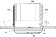
FIG. 5 is a cross-sectional view of the sleeve of the present invention;
fig. 6 is an enlarged schematic view of part B of fig. 5 according to the present invention.
In the figure:
1, a transportation device;
2, a carrying device, 21 slide rails, 22 second slide blocks and 23 clamping jaws;
3 detection device, 31 detection support, 32 actuating cylinder, 321 first spacing, 322 second spacing, 323 actuating strip, 324T type slider, 33 sleeve, 331 spout, 332 gasbag, 333 reset spring, 334 strip groove, 335 layer of polishing, 336 cutter groove, 337 reservoir, 338 toper piece, 34 cutter, 341 spray hole, 35 spacing ring, 351 first slider, 352 strip of polishing, 36 gas hood, 361 venthole, 37 connecting rod, 38 link, 381 recess, 382T type groove.
Detailed Description
To make the objects, technical solutions and advantages of the embodiments of the present invention clearer, the technical solutions of the present invention will be clearly and completely described below with reference to the accompanying drawings, and it is apparent that the described embodiments are some, but not all embodiments of the present invention. All other embodiments, which can be obtained by a person skilled in the art without making any creative effort based on the embodiments in the present invention, belong to the protection scope of the present invention.
Example 1
As shown in fig. 1 to 6, this embodiment 1 provides a polyurethane board feeding system, including: the device comprises a transportation device 1 and a carrying device 21 arranged above the transportation device 1, wherein the carrying device 21 is suitable for carrying the plate to be detected to the transportation device 1, and the transportation device 1 is suitable for transporting the plate (polyurethane plate); detection device 3, detection device 3 sets up 1 top of conveyer, detection device 3 is suitable for and detects panel, has realized the detection to panel punches a hole to inner wall to punching a hole is polished, cuts the jam part of punching a hole when blockking up in punching a hole and makes and punch a hole and open, has ensured the quality of punching a hole on the panel, thereby ensures the quality of panel.
In this embodiment, the transportation device 1 may employ a conveyor belt.
In the present embodiment, the detection device 3 includes: the detection bracket 31, the driving mechanism and the detection mechanism; the detection bracket 31 is erected above the transportation device 1; the driving mechanism is arranged on the detection bracket 31 and is connected with the detection mechanism; the detection mechanism is arranged above the transportation device 1; the driving mechanism is suitable for driving the detection mechanism to approach the conveying device 1 so as to detect the plate through the detection mechanism; the punching hole of the plate is detected through the detection mechanism, burrs and residues on the inner wall of the punching hole are removed, and the quality of the punching hole is ensured so as to ensure the quality of the plate.
In this embodiment, the drive mechanism includes: the driving cylinder 32, a first limit strip 321, a second limit strip 322 and a driving strip 323; the driving cylinder 32 is arranged on the detection bracket 31; the first limiting strip 321 and the second limiting strip 322 are oppositely arranged on the driving cylinder 32, and the length direction of the first limiting strip 321 and the second limiting strip 322 is the same as the lifting direction of the driving cylinder 32; the driving bar 323 is arranged on the driving cylinder 32, and the driving bar 323 is arranged between the first limiting bar 321 and the second limiting bar 322; the driving cylinder 32 is adapted to drive the driving bar 323 to approach or move away from the transportation device 1; the first limiting bar 321 and the second limiting bar 322 can limit the moving direction of the driving bar 323 in the groove 381, so as to ensure that the sleeve 33 extends into the punched hole of the plate.
In this embodiment, the detection mechanism includes: a connecting rod assembly and sleeve 33; the connecting rod 37 assembly is connected with the driving strip 323; the link 37 assembly extends into the sleeve 33; the driving cylinder 32 is adapted to drive the sleeve 33 towards and away from the sheet material on the transport device 1 by means of a driving bar 323.
In this embodiment, a sliding slot 331 is formed in the outer wall of the sleeve 33 along the length direction of the sleeve 33, an air bag 332 is disposed on the lower end surface of the sliding slot 331, and a return spring 333 is disposed on the upper end surface of the sliding slot 331; a strip-shaped groove 334 is formed in the upper end face of the sleeve 33; a polishing layer 335 is arranged on the outer wall of the sleeve 33, the outer wall of the polishing layer 335 is slightly more outside than the position of the cutter 34 exposed out of the cutter groove 336, and when the sleeve 33 extends into the punched hole, the polishing layer 335 is in close contact with the inner wall of the punched hole to polish the inner wall; a cutter groove 336 is circumferentially arranged on the outer wall of the sleeve 33, a cutter 34 is arranged in the cutter groove 336, the blade surface of the cutter 34 faces the bottom surface of the sleeve 33, and the cutter groove 336 is exposed from the blade surface; the connecting rod assembly extends into the strip-shaped groove 334; can polish the burr in the punching hole through layer 335 of polishing, can amputate (remain and can make the unsmooth of punching a hole) the remaining in the punching hole through cutter 34, make originally the not good panel that leads to the through-hole jam of punching a hole effect, its through-hole is unobstructed again.
In this embodiment, the cutting knife 34 is provided with a plurality of liquid spraying holes 341 (the liquid spraying holes 341 may be provided on the cutting edge surface of the cutting knife 34, and the sectional area of the liquid spraying holes 341 may be gradually reduced outwards to block the liquid spraying holes 341 through the tapered blocking piece 338); a liquid storage bag 337 is arranged on the inner wall of the strip-shaped groove 334 and stores colored solution; the reservoir 337 is in communication with the liquid jet 341; a conical plug 338 is arranged in the liquid spraying hole 341, and the tip of the conical plug 338 is exposed out of the liquid spraying hole 341; when the tip of the conical plug 338 is exposed out of the liquid spraying hole 341, the conical plug 338 can plug the liquid spraying hole 341, so that the colored solution in the reservoir 337 is prevented from dripping into the flushing hole.
In this embodiment, the sleeve 33 is sleeved with a limit ring 35; a first sliding block 351 matched with the sliding groove 331 is arranged on the inner wall of the limiting ring 35; one end surface of the first slider 351 is connected with the return spring 333, and the other end surface is connected with the air bag 332; the inner wall of the limiting ring 35 is circumferentially provided with a polishing strip 352; when the limiting ring 35 is sleeved outside the sleeve 33, the limiting ring 35 compresses the air bag 332; the impurity of polishing layer 335 surface can be scraped through spacing ring 35 to polish to cutter 34.
In this embodiment, an air hood 36 is disposed on a lower end surface of the sleeve 33, and a plurality of air outlets 361 are disposed on the air hood 36; the area enclosed by the gas cover 36 and the lower end surface of the sleeve 33 is communicated with the gas bag 332.
In this embodiment, the connecting rod assembly includes: a connecting rod 37 and a connecting block 38; one end of the connecting rod 37 extends into the strip-shaped groove 334 to contact with the bottom surface of the strip-shaped groove 334 (the connecting rod 37 can slide on the bottom surface of the strip-shaped groove 334 and is connected with the bottom surface of the strip-shaped groove 334 so as to drive the sleeve 33 to move through the connecting rod 37), and the other end of the connecting rod 37 is connected with the connecting block 38; a groove 381 is formed in the end face, facing the driving cylinder 32, of the connecting block 38, one side face of the groove 381 is arranged in an inclined mode, and a T-shaped groove 382 is formed in the side face; the driving strip 323 extends into the groove 381, the driving strip 323 is in contact with the inclined side face of the groove 381, a T-shaped sliding block 324 is arranged on the driving strip 323, the T-shaped sliding block 324 is matched with the T-shaped groove 382 to connect the driving strip 323 with the connecting block 38, and the driving strip 323 passes through; the first limiting strip 321 and the second limiting strip 322 are in contact with the side wall of the connecting block 38; when the driving cylinder 32 drives the driving bar 323 to move downwards, the driving bar 323 slides along the inclined plane in the groove 381 of the connecting block 38, at the moment, the sleeve 33 is driven to move downwards, so that the sleeve 33 extends into the punched hole of the plate, the limiting ring 35 is blocked by the plate in the process that the sleeve 33 extends into the punched hole of the plate, and the limiting ring 35 slides in the sliding groove 331 to compress the return spring 333 and stretch the air bag 332; when the sleeve 33 extends into the punched hole, if the punched hole is normal, the inner wall of the punched hole is polished through the polishing layer 335; if the punched hole is abnormal (the inside of the punched hole is remained and blocked, namely the inner diameter of the punched hole is smaller than the standard size), the inner wall of the punched hole is cut by the cutter 34, at the moment, the conical plug piece 338 is squeezed to move towards the inside of the liquid spraying hole 341 to open the liquid spraying hole 341, the driving bar 323 drives the connecting rod 37 to move in the strip-shaped groove 334 to extrude the liquid storage bag 337 when sliding along the inclined plane in the groove 381 of the connecting block 38, and the ink in the liquid storage bag 337 is sprayed to the inner wall of the punched hole through the liquid spraying hole 341; when the driving cylinder 32 drives the driving bar 323 to move upwards to drive the sleeve 33 to extend out of the punched hole, the polishing layer 335 passes through the polishing bar 352, the cutter 34 passes through the polishing bar 352, and the limiting ring 35 presses the air bag 332 after the cutter 34 passes through the polishing bar 352, so that the air in the air bag 332 is blown to the punched hole through the air outlet 361.
At the initial position (at this time, the gas hood 36 is slightly higher than the surface of the plate, which is convenient for rapidly detecting the punched holes on the plate when the plate moves below the detection device 3, so as to improve the detection efficiency, the number of the detection mechanisms can be the same as the number of the punched holes on one plate, so as to facilitate the detection of all the punched holes simultaneously, so as to improve the detection efficiency), the limit ring 35 is located below the cutter groove 336, at this time, the gas bag 332 is in a compressed state, the driving cylinder 32 drives the driving strip 323 to move towards the plate, the driving sleeve 33 gradually extends into the punched holes, the surface of the plate bears the limit strip to lift the limit strip, as the sleeve 33 enters the punched holes, the cutter 34 cuts the residues on the inner wall of the punched holes (because the residues make the inner diameter of the punched holes smaller, the cutter 34 will contact with the residues during the cutting process, at this time, the residues will abut against the conical plug 338 to make the conical plug 338 contract towards the inside of the liquid spray hole 341 to open the liquid spray hole 341, when no residue exists in the punched hole, the conical plug 338 cannot contact with the inner wall of the punched hole, so that the liquid spraying hole 341 is kept blocked), the polishing layer 335 polishes the inner wall of the punched hole, in the process that the sleeve 33 extends into the punched hole, the connecting rod 37 is driven to move on the bottom surface of the strip-shaped groove 334 along with the movement of the driving strip 323 on the surface of the inclined side wall in the groove 381, so as to extrude the liquid storage bag 337, colored liquid in the liquid storage bag 337 is sprayed on the inner wall of the punched hole from the liquid spraying hole 341 (the inner wall of the punched hole is marked, so that the plate can be processed subsequently, for example, the cutting residue is removed, or the punched hole is detected for the second time, so as to ensure smooth punched hole punching), when the driving cylinder 32 drives the driving strip 323 to ascend, the sleeve 33 gradually extends out of the punched hole, at the moment, as the compressed return spring 333 gradually recovers to deform, so as to drive the limiting ring 35 to move downwards relative to the appearance of the sleeve 33, polish layer 335 through polishing strip 352, scrape off the impurity that is stained with when polishing layer 335 polishes to polish cutter 34, compress gasbag 332 this moment when spacing ring 35 resumes to initial position, blow gas in the gasbag 332 to the impurity of punching the hole pair cutting of polishing from venthole 361 and clear away, ensure the quality of panel.
In this embodiment, the carrying device 21 includes: a slide rail 21 erected above the transportation device 1, and a second slide block 22 matched with the slide rail 21 is arranged on the slide rail 21; a clamping jaw 23 is arranged on the second sliding block 22; the clamping jaw 23 is suitable for clamping a plate; after the plate is clamped, the plate is moved along the slide rail 21 by the slide block to be conveyed to the upper part of the conveying device 1, and the plate is placed on the conveying device 1 by the clamping jaw 23.
Example 2
On the basis of embodiment 1, this embodiment 2 further provides a working method of the feeding system of the polyurethane board in embodiment 1, including: the specific working method for detecting the transported plate is described in detail in embodiment 1, and is not described again.
In summary, the present invention provides a transportation device 1, and a carrying device 21 disposed above the transportation device 1, wherein the carrying device 21 is adapted to carry a sheet material to be detected to the transportation device 1, and the transportation device 1 is adapted to transport the sheet material; detection device 3, detection device 3 sets up 1 top of conveyer, detection device 3 is suitable for and detects panel, has realized the detection to panel punches a hole to inner wall to punching a hole is polished, cuts the jam part of punching a hole when blockking up in punching a hole and makes and punch a hole and open, has ensured the quality of punching a hole on the panel, thereby ensures the quality of panel.
The components selected for use in the present application (components not illustrated for specific structures) are all common standard components or components known to those skilled in the art, and the structure and principle thereof can be known to those skilled in the art through technical manuals or through routine experimentation. Moreover, the software programs referred to in the present application are all prior art, and the present application does not relate to any improvement of the software programs.
In the description of the embodiments of the present invention, unless otherwise explicitly specified or limited, the terms "mounted," "connected," and "connected" are to be construed broadly, e.g., as meaning either a fixed connection, a removable connection, or an integral connection; can be mechanically or electrically connected; they may be connected directly or indirectly through intervening media, or they may be interconnected between two elements. The specific meanings of the above terms in the present invention can be understood in specific cases to those skilled in the art.
In the description of the present invention, it should be noted that the terms "center", "upper", "lower", "left", "right", "vertical", "horizontal", "inner", "outer", etc., indicate orientations or positional relationships based on the orientations or positional relationships shown in the drawings, and are only for convenience of description and simplicity of description, but do not indicate or imply that the device or element being referred to must have a particular orientation, be constructed and operated in a particular orientation, and thus, should not be construed as limiting the present invention. Furthermore, the terms "first," "second," and "third" are used for descriptive purposes only and are not to be construed as indicating or implying relative importance.
In the several embodiments provided in the present application, it should be understood that the disclosed system, apparatus and method may be implemented in other ways. The above-described embodiments of the apparatus are merely illustrative, and for example, the division of the units is only one logical division, and there may be other divisions when actually implemented, and for example, a plurality of units or components may be combined or integrated into another system, or some features may be omitted, or not executed. In addition, the shown or discussed mutual coupling or direct coupling or communication connection may be an indirect coupling or communication connection of devices or units through some communication interfaces, and may be in an electrical, mechanical or other form.
The units described as separate parts may or may not be physically separate, and parts displayed as units may or may not be physical units, may be located in one place, or may be distributed on a plurality of network units. Some or all of the units can be selected according to actual needs to achieve the purpose of the solution of the embodiment.
In addition, functional units in the embodiments of the present invention may be integrated into one processing unit, or each unit may exist alone physically, or two or more units are integrated into one unit.
In light of the foregoing description of the preferred embodiment of the present invention, many modifications and variations will be apparent to those skilled in the art without departing from the spirit and scope of the invention. The technical scope of the present invention is not limited to the content of the specification, and must be determined according to the scope of the claims.
Claims (10)
1. A polyurethane board feeding system, comprising:
a transportation device, and
the carrying device is arranged above the conveying device and is suitable for carrying the plate to be detected to the conveying device, and the conveying device is suitable for conveying the plate;
the detection device is arranged above the conveying device and is suitable for detecting the plates.
2. The polyurethane board feeding system according to claim 1,
the detection device includes: the device comprises a detection bracket, a driving mechanism and a detection mechanism;
the detection bracket is erected above the conveying device;
the driving mechanism is arranged on the detection bracket and is connected with the detection mechanism;
the detection mechanism is arranged above the transportation device;
the driving mechanism is suitable for driving the detection mechanism to approach the conveying device so as to detect the plate through the detection mechanism.
3. The polyurethane board feeding system according to claim 2,
the drive mechanism includes: the device comprises a driving cylinder, a first limiting strip, a second limiting strip and a driving strip;
the driving cylinder is arranged on the detection bracket;
the first limiting strip and the second limiting strip are oppositely arranged on the driving cylinder, and the length directions of the first limiting strip and the second limiting strip are the same as the lifting direction of the driving cylinder;
the driving strip is arranged on the driving cylinder and is arranged between the first limiting strip and the second limiting strip;
the driving cylinder is suitable for driving the driving strip to move towards or away from the conveying device.
4. The polyurethane board feeding system according to claim 3,
the detection mechanism includes: a connecting rod assembly and a sleeve;
the connecting rod assembly is connected with the driving strip;
the connecting rod assembly extends into the sleeve;
the driving cylinder is suitable for driving the sleeve to approach or move away from the plate on the conveying device through the driving strip.
5. The polyurethane board feeding system according to claim 4,
the outer wall of the sleeve is provided with a sliding chute along the length direction of the sleeve, the lower end face of the sliding chute is provided with an air bag, and the upper end face of the sliding chute is provided with a return spring;
a strip-shaped groove is formed in the upper end face of the sleeve;
a polishing layer is arranged on the outer wall of the sleeve;
a cutter groove is circumferentially arranged on the outer wall of the sleeve, a cutter is arranged in the cutter groove, and the blade surface of the cutter faces the bottom surface of the sleeve;
the connecting rod assembly extends into the strip-shaped groove.
6. The polyurethane board feeding system according to claim 5,
the cutter is provided with a plurality of liquid spraying holes;
a liquid storage bag is arranged on the inner wall of the strip-shaped groove;
the liquid storage bag is communicated with the liquid spraying hole;
and a conical plugging piece is arranged in the liquid spraying hole, and the tip part of the conical plugging piece is exposed out of the liquid spraying hole.
7. The polyurethane board feeding system according to claim 6,
a limiting ring is sleeved outside the sleeve;
a first sliding block matched with the sliding groove is arranged on the inner wall of the limiting ring;
one end face of the first sliding block is connected with the return spring, and the other end face of the first sliding block is connected with the air bag;
polishing strips are circumferentially arranged on the inner wall of the limiting ring;
when the limiting ring is sleeved outside the sleeve, the limiting ring compresses the air bag;
the lower end face of the sleeve is provided with an air hood, and the air hood is provided with a plurality of air outlet holes;
the area enclosed by the gas cover and the lower end surface of the sleeve is communicated with the air bag.
8. The polyurethane panel feeding system according to claim 7,
the connecting rod assembly includes: a connecting rod and a connecting block;
one end of the connecting rod extends into the strip-shaped groove to be in contact with the bottom surface of the strip-shaped groove, and the other end of the connecting rod is connected with the connecting block;
the end face, facing the driving cylinder, of the connecting block is provided with a groove, one side face of the groove is obliquely arranged, and a T-shaped groove is formed in the side face;
the driving strip extends into the groove and is in contact with the inclined side face of the groove, a T-shaped sliding block is arranged on the driving strip, and the T-shaped sliding block is matched with the T-shaped groove;
the first limiting strip and the second limiting strip are in contact with the side wall of the connecting block;
when the driving cylinder drives the driving strip to move downwards, the driving strip slides along the inclined plane in the groove of the connecting block, the sleeve is driven to move downwards to enable the sleeve to extend into the punched hole of the plate, the limiting ring is blocked by the plate in the process that the sleeve extends into the punched hole of the plate, and the limiting ring slides in the sliding groove to compress the return spring and stretch the air bag;
when the sleeve extends into the punched hole, if the punched hole is normal, polishing the inner wall of the punched hole through the polishing layer;
if the punched hole is abnormal, cutting the inner wall of the punched hole through a cutter, extruding the conical plug piece to move towards the interior of the liquid spraying hole to open the liquid spraying hole, driving the connecting rod to move in the strip-shaped groove to extrude the liquid storage bag when the driving strip slides along the inclined plane in the groove of the connecting block, and spraying ink in the liquid storage bag to the inner wall of the punched hole through the liquid spraying hole;
when driving actuating cylinder drive strip rebound and drive the sleeve and stretch out and punch a hole, the layer of polishing is through the strip of polishing to the cutter is through the strip of polishing, and the spacing ring extrusion gasbag makes the gas in the gasbag blow to punching a hole through the venthole behind the cutter through the strip of polishing.
9. The polyurethane panel feeding system according to claim 8,
the carrying device includes: the sliding rail is erected above the conveying device, and a second sliding block matched with the sliding rail is arranged on the sliding rail;
a clamping jaw is arranged on the second sliding block;
the clamping jaw is suitable for clamping a plate;
after the plates are clamped, the sliding blocks move along the sliding rails to convey the plates to the upper side of the conveying device, and the plates are placed on the conveying device through the clamping jaws.
10. A method of operating the polyurethane panel feeding system of claim 1, comprising:
and detecting the transported plates.
Priority Applications (1)
| Application Number | Priority Date | Filing Date | Title |
|---|---|---|---|
| CN202211196273.9A CN115284123A (en) | 2022-09-29 | 2022-09-29 | Polyurethane board feeding system and working method |
Applications Claiming Priority (1)
| Application Number | Priority Date | Filing Date | Title |
|---|---|---|---|
| CN202211196273.9A CN115284123A (en) | 2022-09-29 | 2022-09-29 | Polyurethane board feeding system and working method |
Publications (1)
| Publication Number | Publication Date |
|---|---|
| CN115284123A true CN115284123A (en) | 2022-11-04 |
Family
ID=83834341
Family Applications (1)
| Application Number | Title | Priority Date | Filing Date |
|---|---|---|---|
| CN202211196273.9A Pending CN115284123A (en) | 2022-09-29 | 2022-09-29 | Polyurethane board feeding system and working method |
Country Status (1)
| Country | Link |
|---|---|
| CN (1) | CN115284123A (en) |
Cited By (2)
| Publication number | Priority date | Publication date | Assignee | Title |
|---|---|---|---|---|
| CN118106403A (en) * | 2024-04-30 | 2024-05-31 | 淮安协盛电器有限公司 | Cast aluminum end cover heat dissipation hole punching device |
| CN118595287A (en) * | 2024-08-07 | 2024-09-06 | 江苏君华特种高分子材料股份有限公司 | Sheet metal stamping tooling and polyetheretherketone production process |
Citations (9)
| Publication number | Priority date | Publication date | Assignee | Title |
|---|---|---|---|---|
| US6769958B1 (en) * | 2002-08-21 | 2004-08-03 | Howard W. Grivna | Material removal monitor |
| JP2005212059A (en) * | 2004-01-30 | 2005-08-11 | Foundation For The Promotion Of Industrial Science | Tubular passage device |
| CN110434697A (en) * | 2019-09-16 | 2019-11-12 | 苏州德佑昊自动化设备有限公司 | A kind of hole aluminium alloy wheel hub PCD intelligence sander and polishing process |
| CN210209720U (en) * | 2019-05-31 | 2020-03-31 | 黄小娟 | Hole repairing device for workpiece for machining |
| CN112045531A (en) * | 2020-09-23 | 2020-12-08 | 彭良九 | Chip polishing mechanism capable of testing and detecting flatness of chip |
| KR102195282B1 (en) * | 2019-09-05 | 2020-12-24 | 박정순 | processing apparatus |
| CN112571648A (en) * | 2021-01-04 | 2021-03-30 | 南京诺泽盈商贸有限公司 | Integrative quartzy perforating device of polishing |
| CN112588944A (en) * | 2020-11-17 | 2021-04-02 | 金肯职业技术学院 | Punching method of automobile front protective cover edge punching mechanism |
| CN213225406U (en) * | 2020-07-31 | 2021-05-18 | 正安县炫耀乐器制造有限公司 | A tool bit of polishing for guitar closes bucket sound hole |
-
2022
- 2022-09-29 CN CN202211196273.9A patent/CN115284123A/en active Pending
Patent Citations (9)
| Publication number | Priority date | Publication date | Assignee | Title |
|---|---|---|---|---|
| US6769958B1 (en) * | 2002-08-21 | 2004-08-03 | Howard W. Grivna | Material removal monitor |
| JP2005212059A (en) * | 2004-01-30 | 2005-08-11 | Foundation For The Promotion Of Industrial Science | Tubular passage device |
| CN210209720U (en) * | 2019-05-31 | 2020-03-31 | 黄小娟 | Hole repairing device for workpiece for machining |
| KR102195282B1 (en) * | 2019-09-05 | 2020-12-24 | 박정순 | processing apparatus |
| CN110434697A (en) * | 2019-09-16 | 2019-11-12 | 苏州德佑昊自动化设备有限公司 | A kind of hole aluminium alloy wheel hub PCD intelligence sander and polishing process |
| CN213225406U (en) * | 2020-07-31 | 2021-05-18 | 正安县炫耀乐器制造有限公司 | A tool bit of polishing for guitar closes bucket sound hole |
| CN112045531A (en) * | 2020-09-23 | 2020-12-08 | 彭良九 | Chip polishing mechanism capable of testing and detecting flatness of chip |
| CN112588944A (en) * | 2020-11-17 | 2021-04-02 | 金肯职业技术学院 | Punching method of automobile front protective cover edge punching mechanism |
| CN112571648A (en) * | 2021-01-04 | 2021-03-30 | 南京诺泽盈商贸有限公司 | Integrative quartzy perforating device of polishing |
Cited By (3)
| Publication number | Priority date | Publication date | Assignee | Title |
|---|---|---|---|---|
| CN118106403A (en) * | 2024-04-30 | 2024-05-31 | 淮安协盛电器有限公司 | Cast aluminum end cover heat dissipation hole punching device |
| CN118106403B (en) * | 2024-04-30 | 2024-07-02 | 淮安协盛电器有限公司 | Cast aluminum end cover heat dissipation hole punching device |
| CN118595287A (en) * | 2024-08-07 | 2024-09-06 | 江苏君华特种高分子材料股份有限公司 | Sheet metal stamping tooling and polyetheretherketone production process |
Similar Documents
| Publication | Publication Date | Title |
|---|---|---|
| CN109794992B (en) | Automatic plate drilling system and control method thereof | |
| CN103341548B (en) | Automatic feed dividing stamping-out composite die | |
| CN104276751A (en) | Bonded substrate processing apparatus | |
| CN117066584B (en) | Efficient transverse shearing system for cutting yoke-type silicon steel sheet | |
| CN207983427U (en) | A kind of Paperboard cutting mechanism | |
| CN204976828U (en) | Cross cutting machine of wasting discharge | |
| CN106239610A (en) | A kind of automatic punch of flexible circuit board | |
| CN212241693U (en) | Plastic pelleter with cutter cleaning function | |
| CN105034078A (en) | Blowing type die-cutting machine | |
| CN112959733A (en) | Carton cross cutting machine | |
| CN115229891B (en) | Polyurethane plate conveying system and method | |
| CN219006152U (en) | Slitter is used in vegetables processing | |
| CN208613477U (en) | Perforation processing unit (plant) | |
| CN214562039U (en) | Automatic edge removing machine | |
| CN104874854B (en) | PCB (printed circuit board) shearing machine | |
| CN212418748U (en) | Automatic change RFID label detection device | |
| CN211135140U (en) | Anti-adhesion waste punching and shearing die | |
| CN211839080U (en) | Sorting device for defective products | |
| CN223421952U (en) | Paper separation device | |
| CN220197795U (en) | Label cutting blanking mechanism | |
| CN218905497U (en) | Workpiece corner extrusion structure | |
| CN204977079U (en) | Clean glass cutting machine easy to push | |
| CN223507257U (en) | Waste belt tail shearing device | |
| CN205185060U (en) | Glazed tiles make -up machine | |
| CN213034802U (en) | Hot die cutting device for paper product processing |
Legal Events
| Date | Code | Title | Description |
|---|---|---|---|
| PB01 | Publication | ||
| PB01 | Publication | ||
| SE01 | Entry into force of request for substantive examination | ||
| SE01 | Entry into force of request for substantive examination | ||
| RJ01 | Rejection of invention patent application after publication | ||
| RJ01 | Rejection of invention patent application after publication |
Application publication date: 20221104 |