CN115284060A - Numerical control processing production prevent mistake processing and blow in real time bits clearance mechanism - Google Patents
Numerical control processing production prevent mistake processing and blow in real time bits clearance mechanism Download PDFInfo
- Publication number
- CN115284060A CN115284060A CN202211077076.5A CN202211077076A CN115284060A CN 115284060 A CN115284060 A CN 115284060A CN 202211077076 A CN202211077076 A CN 202211077076A CN 115284060 A CN115284060 A CN 115284060A
- Authority
- CN
- China
- Prior art keywords
- cylinder
- numerical control
- machine tool
- fixedly installed
- chip blowing
- Prior art date
- Legal status (The legal status is an assumption and is not a legal conclusion. Google has not performed a legal analysis and makes no representation as to the accuracy of the status listed.)
- Pending
Links
Images


Classifications
-
- B—PERFORMING OPERATIONS; TRANSPORTING
- B23—MACHINE TOOLS; METAL-WORKING NOT OTHERWISE PROVIDED FOR
- B23Q—DETAILS, COMPONENTS, OR ACCESSORIES FOR MACHINE TOOLS, e.g. ARRANGEMENTS FOR COPYING OR CONTROLLING; MACHINE TOOLS IN GENERAL CHARACTERISED BY THE CONSTRUCTION OF PARTICULAR DETAILS OR COMPONENTS; COMBINATIONS OR ASSOCIATIONS OF METAL-WORKING MACHINES, NOT DIRECTED TO A PARTICULAR RESULT
- B23Q11/00—Accessories fitted to machine tools for keeping tools or parts of the machine in good working condition or for cooling work; Safety devices specially combined with or arranged in, or specially adapted for use in connection with, machine tools
- B23Q11/0042—Devices for removing chips
- B23Q11/005—Devices for removing chips by blowing
-
- Y—GENERAL TAGGING OF NEW TECHNOLOGICAL DEVELOPMENTS; GENERAL TAGGING OF CROSS-SECTIONAL TECHNOLOGIES SPANNING OVER SEVERAL SECTIONS OF THE IPC; TECHNICAL SUBJECTS COVERED BY FORMER USPC CROSS-REFERENCE ART COLLECTIONS [XRACs] AND DIGESTS
- Y02—TECHNOLOGIES OR APPLICATIONS FOR MITIGATION OR ADAPTATION AGAINST CLIMATE CHANGE
- Y02P—CLIMATE CHANGE MITIGATION TECHNOLOGIES IN THE PRODUCTION OR PROCESSING OF GOODS
- Y02P70/00—Climate change mitigation technologies in the production process for final industrial or consumer products
- Y02P70/10—Greenhouse gas [GHG] capture, material saving, heat recovery or other energy efficient measures, e.g. motor control, characterised by manufacturing processes, e.g. for rolling metal or metal working
Landscapes
- Engineering & Computer Science (AREA)
- Mechanical Engineering (AREA)
- Automatic Tool Replacement In Machine Tools (AREA)
Abstract
本发明涉及一种数控加工生产的防误加工实时吹屑清理机构,包括数控机床,所述数控机床的正面滑动安装有舱门,所述数控机床的内底壁活动安装有加工平台,所述数控机床的左侧壁活动安装有制动杆,所述数控机床内部的右侧固定安装有推料机构。该数控加工生产的防误加工实时吹屑清理机构,通过设置吹屑机构,支撑轴左右移动来调节吹屑筒和收集筒之间的距离,同时还可以通过传动电机的转动拉动收集筒在凹槽的内部滑动,通过连接轴进行制动,从而将收集筒向上方转动,调节收集筒的位置,以便于将碎屑更好的收集,通过风扇产生的风将碎屑吹入收集筒进行统一处理,清理方便,从而避免了碎屑进入数控机床的内部,以提高数控机床的使用寿命。
The invention relates to an error-proof real-time chip blowing cleaning mechanism produced by numerical control machining, which comprises a numerical control machine tool, a cabin door is slidably installed on the front of the numerical control machine tool, and a processing platform is movably installed on the inner bottom wall of the numerical control machine tool. A brake lever is movably installed on the left side wall of the CNC machine tool, and a pushing mechanism is fixedly installed on the right side inside the CNC machine tool. The anti-misprocessing real-time chip blowing cleaning mechanism produced by CNC machining can adjust the distance between the chip blowing cylinder and the collecting cylinder by setting the chip blowing mechanism and moving the support shaft left and right. The inside of the groove slides and is braked by the connecting shaft, so as to rotate the collection cylinder upwards, adjust the position of the collection cylinder to better collect the debris, and blow the debris into the collection cylinder through the wind generated by the fan for unification It is easy to handle and clean, so as to avoid debris from entering the interior of the CNC machine tool, so as to improve the service life of the CNC machine tool.
Description
技术领域technical field
本发明涉及数控加工生产技术领域,具体为一种数控加工生产的防误加工实时吹屑清理机构。The invention relates to the technical field of numerical control machining production, in particular to a real-time chip blowing and cleaning mechanism for preventing mis-machining and production of numerical control machining.
背景技术Background technique
数控加工是指在数控机床上进行零件加工的一种工艺方法,数控机床加工与传统机床加工的工艺规程从总体上说是一致的,但也发生了明显的变化。用数字信息控制零件和刀具位移的机械加工方法,它是解决零件品种多变、批量小、形状复杂、精度高等问题和实现高效化和自动化加工的有效途径。CNC machining refers to a process method for processing parts on CNC machine tools. The process regulations of CNC machine tool processing and traditional machine tool processing are generally consistent, but significant changes have also taken place. The mechanical processing method of controlling the displacement of parts and tools with digital information is an effective way to solve the problems of variable parts, small batches, complex shapes, and high precision and to achieve high-efficiency and automatic processing.
数控加工是由控制系统发出指令使刀具作符合要求的各种运动,以数字和字母形式表示工件的形状和尺寸等技术要求和加工工艺要求进行的加工,它泛指在数控机床上进行零件加工的工艺过程,数控机床进行零件加工的时候会产生大量的碎屑,这些碎屑会随处掉落,甚至进入到机床的内部,不便于清理,长期堆积会对机床造成损伤,而且不具备紧急锁死功能,在出现错误操作时无法第一时间使得设备停止,常常生产处残次品,故而提出一种数控加工生产的防误加工实时吹屑清理机构来解决上述问题。Numerical control machining is a process in which the control system issues instructions to make the tool perform various movements that meet the requirements, and express the technical requirements and processing technology requirements such as the shape and size of the workpiece in the form of numbers and letters. It generally refers to the processing of parts on CNC machine tools. During the process of CNC machine tools, a large amount of debris will be generated when the parts are processed. These debris will fall everywhere and even enter the interior of the machine tool. It is not easy to clean. Long-term accumulation will cause damage to the machine tool, and there is no emergency lock. Dead function, in the event of wrong operation, the equipment cannot be stopped at the first time, and defective products are often produced. Therefore, a real-time chip blowing mechanism for preventing mis-processing and production of CNC machining is proposed to solve the above problems.
发明内容Contents of the invention
针对现有技术的不足,本发明提供了一种数控加工生产的防误加工实时吹屑清理机构,具备自动清理碎屑和防误触自动锁死等优点,解决了数控机床进行零件加工的时候会产生大量的碎屑,这些碎屑会随处掉落,甚至进入到机床的内部,不便于清理,长期堆积会对机床造成损伤,而且不具备紧急锁死功能,在出现错误操作时无法第一时间使得设备停止,常常生产处残次品的问题。Aiming at the deficiencies of the prior art, the present invention provides a real-time chip blowing mechanism for preventing mis-machining produced by CNC machining, which has the advantages of automatic cleaning of debris and automatic locking of anti-mistouch, etc. A large amount of debris will be generated, which will fall everywhere and even enter the inside of the machine tool, which is not easy to clean. Long-term accumulation will cause damage to the machine tool, and it does not have an emergency lock function, so it cannot be the first time when a wrong operation occurs Time causes equipment to stop, often producing defective products.
为实现上述目的,本发明提供如下技术方案:一种数控加工生产的防误加工实时吹屑清理机构,包括数控机床,所述数控机床的正面滑动安装有舱门,所述数控机床的内底壁活动安装有加工平台,所述数控机床的左侧壁活动安装有制动杆,所述数控机床内部的右侧固定安装有推料机构,所述加工平台的顶部固定安装有吹屑机构;In order to achieve the above object, the present invention provides the following technical solutions: a real-time chip blowing and cleaning mechanism for preventing mis-machining produced by numerical control machining, including a numerical control machine tool, a hatch door is slidingly installed on the front of the numerical control machine tool, and the inner bottom of the numerical control machine tool is A processing platform is movably installed on the wall, a brake lever is movably installed on the left side wall of the CNC machine tool, a pushing mechanism is fixedly installed on the right side inside the CNC machine tool, and a chip blowing mechanism is fixedly installed on the top of the processing platform;
所述推料机构包括安装筒,所述数控机床的右侧壁固定安装有安装筒,所述安装筒的内壁的顶部与底部均固定安装有电动滑轨,所述安装筒的左侧滑动安装有推动杆,所述推动杆的顶部与底部均固定安装有滑块,所述安装筒的左侧固定安装有锁紧筒,所述锁紧筒的内底壁和内顶壁均固定活动安装有支撑杆,两个所述支撑杆相对的一侧均活动安装有连接杆,两个伸缩支撑杆左侧相对的一端均活动安装有卡板,所述锁紧筒的内底壁和内顶壁均固定安装有电动推杆;The pushing mechanism includes an installation cylinder, the right side wall of the CNC machine tool is fixedly installed with an installation cylinder, the top and bottom of the inner wall of the installation cylinder are fixedly equipped with electric slide rails, and the left side of the installation cylinder is slidingly installed There is a push rod, the top and bottom of the push rod are fixedly installed with sliders, the left side of the installation cylinder is fixedly installed with a locking cylinder, and the inner bottom wall and inner top wall of the locking cylinder are fixed and movable There are support rods, connecting rods are movably installed on the opposite sides of the two support rods, clamping plates are movably installed on the opposite ends of the left sides of the two telescopic support rods, and the inner bottom wall and inner top of the locking cylinder Electric push rods are fixedly installed on the walls;
所述吹屑机构包括底座,所述加工平台的顶部固定安装有底座,所述底座的右侧壁固定安装有液压推杆,所述底座的内部固定安装有主轴,所述液压推杆的输出轴处固定安装有支撑架,所述支撑架的顶部固定安装有工作架,所述工作架顶部的右侧活动安装有收集筒,所述工作架顶部的左侧滑动安装有支撑轴,所述支撑轴的内部固定安装有吹屑筒,所述吹屑筒的内部固定安装有风扇,所述工作架的右端固定安装有传动电机,所述传动电机的输出轴处固定安装有半圆转盘,所述半圆转盘的外表面开设有凹槽,所述半圆转盘与收集筒之间活动安装有连接轴,所述工作架的顶部固定安装有限位杆,所述工作架的顶部活动安装有推板,所述工作架的背面转动连接有驱动轮,所述工作架的背面固定安装有驱动电机。The chip blowing mechanism includes a base, a base is fixedly installed on the top of the processing platform, a hydraulic push rod is fixedly installed on the right side wall of the base, a main shaft is fixedly installed inside the base, and the output of the hydraulic push rod A support frame is fixedly installed at the shaft, a work frame is fixedly installed on the top of the support frame, a collection tube is movably installed on the right side of the top of the work frame, and a support shaft is slidably installed on the left side of the top of the work frame. The inside of the support shaft is fixedly equipped with a chip blower, the inside of the chip blower is fixedly installed with a fan, the right end of the work frame is fixedly installed with a transmission motor, and the output shaft of the transmission motor is fixedly installed with a semicircular turntable. The outer surface of the semicircular turntable is provided with grooves, a connecting shaft is movably installed between the semicircle turntable and the collection cylinder, a limit rod is fixedly installed on the top of the work frame, and a push plate is movably installed on the top of the work frame. A drive wheel is rotatably connected to the back of the work frame, and a drive motor is fixedly installed on the back of the work frame.
进一步,所述加工平台的顶部固定安装有加工头,且加工头处于吹屑筒和收集筒之间。Further, a processing head is fixedly installed on the top of the processing platform, and the processing head is located between the chip blowing cylinder and the collecting cylinder.
进一步,所述底座的顶部开设有安装槽,所述主轴处于液压推杆的上方。Further, an installation groove is opened on the top of the base, and the main shaft is above the hydraulic push rod.
进一步,所述支撑架架滑动安装于主轴的外表面,所述吹屑筒向下方倾斜三十度,且吹屑筒的左右两侧均固定安装有滤网。Further, the support frame is slidably installed on the outer surface of the main shaft, the chip blowing cylinder is inclined downward at 30 degrees, and filter screens are fixedly installed on the left and right sides of the chip blowing cylinder.
进一步,所述半圆转盘滑动安装于工作架的正面,所述收集筒底部的右侧滑动安装于凹槽的内部。Further, the semicircular turntable is slidably installed on the front of the working frame, and the right side of the bottom of the collecting tube is slidably installed in the groove.
进一步,所述限位杆的右端与工作架滑动连接,所述推板的左侧与支撑轴固定连接。Further, the right end of the limit rod is slidably connected with the working frame, and the left side of the push plate is fixedly connected with the support shaft.
进一步,所述工作架的顶部开设有滑槽,所述推板滑动安装于滑槽的内部,所述推板底部的后侧与驱动轮啮合。Further, a chute is opened on the top of the work frame, the push plate is slidably installed inside the chute, and the rear side of the bottom of the push plate is engaged with the driving wheel.
进一步,所述驱动电机与驱动轮之间通过皮带传动连接,所述推动杆滑动安装有锁紧筒的内部,所述连接杆远离支撑杆的一端与卡板滑动连接。Further, the drive motor is connected to the drive wheel through a belt transmission, the push rod is slidably installed inside the locking cylinder, and the end of the connecting rod away from the support rod is slidably connected to the clamping plate.
进一步,所述推动杆卡接于两个卡板相对的一侧,且两个卡板相对的一侧均固定安装有等距离排列的卡齿,所述电动推杆远离锁紧筒内壁的一端与支撑杆铰接。Further, the push rod is clamped on the opposite side of the two clamping plates, and the opposite sides of the two clamping plates are fixedly equipped with locking teeth arranged equidistantly, and the end of the electric push rod is far away from the inner wall of the locking cylinder Hinged with support rod.
与现有技术相比,本申请的技术方案具备以下有益效果:Compared with the prior art, the technical solution of the present application has the following beneficial effects:
1、该数控加工生产的防误加工实时吹屑清理机构,通过设置吹屑机构,在数控加工生产的过程中,加工零件所产生的碎屑将会在加工平台的周围飞溅,将吹屑筒和收集筒置于加工平台顶部的加工头的左右两侧,在调节的时候,可通过液压推杆带动支撑架在主轴上进行左右移动调节位置,再通过驱动电机通过皮带带动驱动轮进行转动,驱动轮将会带动推板在工作架的顶部进行左右的滑动,从而带动支撑轴左右移动来调节吹屑筒和收集筒之间的距离,同时还可以通过传动电机的转动拉动收集筒在凹槽的内部滑动,通过连接轴进行制动,从而将收集筒向上方转动,调节收集筒的位置,以便于将碎屑更好的收集,通过风扇产生的风将碎屑吹入收集筒进行统一处理,清理方便,从而避免了碎屑进入数控机床的内部,以提高数控机床的使用寿命。1. The anti-mis-machining real-time chip blowing and cleaning mechanism of the CNC machining production, by setting the chip blowing mechanism, in the process of CNC machining production, the chips generated by the processed parts will splash around the processing platform, and the chip blowing cylinder will The collection cylinder is placed on the left and right sides of the processing head on the top of the processing platform. When adjusting, the hydraulic push rod can drive the support frame to move left and right on the main shaft to adjust the position, and then drive the drive wheel to rotate through the drive motor through the belt. The driving wheel will drive the push plate to slide left and right on the top of the work frame, thereby driving the support shaft to move left and right to adjust the distance between the chip blower and the collection cylinder, and at the same time, the rotation of the transmission motor can pull the collection cylinder in the groove The internal sliding of the shaft is braked by the connecting shaft, so that the collection cylinder is rotated upwards, and the position of the collection cylinder is adjusted to facilitate better collection of debris. The wind generated by the fan blows the debris into the collection cylinder for unified processing , It is easy to clean, so as to avoid debris from entering the interior of the CNC machine tool, so as to improve the service life of the CNC machine tool.
2、该数控加工生产的防误加工实时吹屑清理机构,通过设置推料机构,在出现错误操作的时候,通过数控机床的控制系统控制电动推杆启动,通过电动推杆带动支撑杆向推杆的一端进行移动,移动之后将会使得连接杆与支撑杆之间的距离扩大,从而将卡板于推杆的外表面紧密贴合,通过卡齿来增加摩擦力,增加卡接的稳定性,这样就可以在第一时间将推杆的夹持紧固和锁定位置,避免其在出现误操作之后还会出现延迟操作,有效避免了错误操作对零件加工损坏,让数控机床加工零件的精准度提高,增加零件加工的质量。2. The anti-mis-processing real-time chip blowing and cleaning mechanism produced by the CNC machining, by setting the pushing mechanism, when there is a wrong operation, the control system of the CNC machine tool controls the electric push rod to start, and the electric push rod drives the support rod to push One end of the rod is moved, and the distance between the connecting rod and the support rod will be enlarged after the movement, so that the clamping plate is closely attached to the outer surface of the push rod, and the friction force is increased through the clamping teeth to increase the stability of the clamping connection , so that the clamping and locking position of the push rod can be fastened at the first time, avoiding the delayed operation after the misoperation, effectively avoiding the damage to the part processing caused by the misoperation, and allowing the precision of the CNC machine tool to process the parts The degree is improved and the quality of parts processing is increased.
附图说明Description of drawings
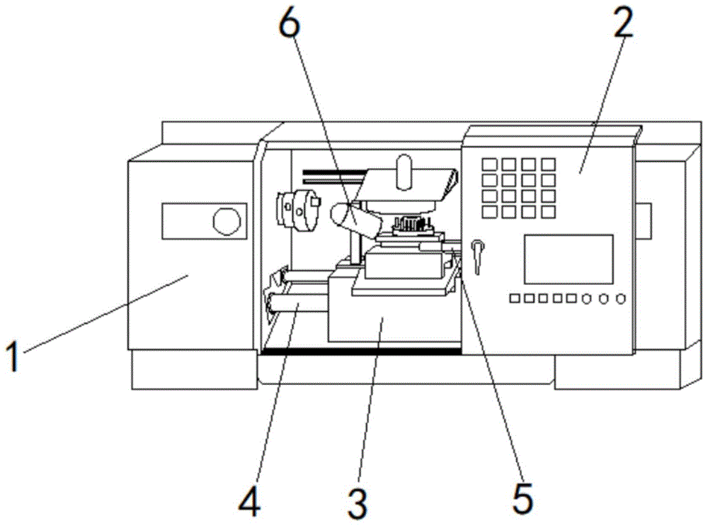
图1为本发明一种数控加工生产的防误加工实时吹屑清理机构结构示意图;Fig. 1 is a schematic structural diagram of a real-time chip blowing and cleaning mechanism for preventing misprocessing produced by numerical control machining;
图2为本发明一种数控加工生产的防误加工实时吹屑清理机构吹屑机构结构示意图;Fig. 2 is a structural schematic diagram of a chip blowing mechanism of a real-time chip blowing cleaning mechanism for preventing misprocessing produced by numerical control processing;
图3为本发明一种数控加工生产的防误加工实时吹屑清理机构图2中A处结构放大图;Fig. 3 is an enlarged view of the structure at A in Fig. 2 of an anti-mis-machining real-time chip blowing and cleaning mechanism produced by numerical control processing;
图4为本发明一种数控加工生产的防误加工实时吹屑清理机构工作架俯视剖视图;Fig. 4 is a top sectional view of the working frame of the anti-mis-machining real-time chip blowing and cleaning mechanism produced by numerical control processing;
图5为本发明一种数控加工生产的防误加工实时吹屑清理机构推料机构结构示意图;Fig. 5 is a schematic structural diagram of a material pushing mechanism of a real-time chip blowing and cleaning mechanism for preventing misprocessing produced by numerical control processing;
图6为本发明一种数控加工生产的防误加工实时吹屑清理机构图5中B处结构放大图。Fig. 6 is an enlarged view of the structure at B in Fig. 5 of a real-time chip blowing and cleaning mechanism for preventing mis-machining produced by numerical control processing according to the present invention.
图中:1、数控机床;2、舱门;3、加工平台;4、制动杆;5、推料机构;6、吹屑机构;501、安装筒;502、电动滑轨;503、滑块;504、推动杆;505、锁紧筒;506、支撑杆;507、连接杆;508、卡板;509、电动推杆;601、底座;602、液压推杆;603、主轴;604、支撑架;605、工作架;606、收集筒;607、支撑轴;608、吹屑筒;609、风扇;610、传动电机;611、半圆转盘;612、凹槽;613、连接轴;614、限位杆;615、推板;616、驱动轮;617、驱动电机。In the figure: 1. CNC machine tool; 2. Hatch door; 3. Processing platform; 4. Brake lever; 5. Pushing mechanism; 6. Chip blowing mechanism; block; 504, push rod; 505, locking cylinder; 506, support rod; 507, connecting rod; 508, clamping plate; 509, electric push rod; 601, base; 602, hydraulic push rod; Support frame; 605, working frame; 606, collection cylinder; 607, support shaft; 608, blowing dust cylinder; 609, fan; 610, transmission motor; 611, semicircle turntable; 612, groove; 613, connecting shaft; Limit rod; 615, push plate; 616, drive wheel; 617, drive motor.
具体实施方式Detailed ways
下面将结合本发明实施例中的附图,对本发明实施例中的技术方案进行清楚、完整地描述,显然,所描述的实施例仅仅是本发明一部分实施例,而不是全部的实施例。基于本发明中的实施例,本领域普通技术人员在没有做出创造性劳动前提下所获得的所有其他实施例,都属于本发明保护的范围。The following will clearly and completely describe the technical solutions in the embodiments of the present invention with reference to the accompanying drawings in the embodiments of the present invention. Obviously, the described embodiments are only some, not all, embodiments of the present invention. Based on the embodiments of the present invention, all other embodiments obtained by persons of ordinary skill in the art without making creative efforts belong to the protection scope of the present invention.
请参阅图1-6,本实施例中的一种数控加工生产的防误加工实时吹屑清理机构,包括数控机床1,数控机床1的正面滑动安装有舱门2,数控机床1的内底壁活动安装有加工平台3,数控机床1的左侧壁活动安装有制动杆4,数控机床1内部的右侧固定安装有推料机构5,加工平台3的顶部固定安装有吹屑机构6;Please refer to Fig. 1-6, a kind of anti-mis-processing real-time chip blowing mechanism produced by CNC machining in this embodiment includes a
推料机构5包括安装筒501,数控机床1的右侧壁固定安装有安装筒501,安装筒501的内壁的顶部与底部均固定安装有电动滑轨502,安装筒501的左侧滑动安装有推动杆504,推动杆504的顶部与底部均固定安装有滑块503,安装筒501的左侧固定安装有锁紧筒505,锁紧筒505的内底壁和内顶壁均固定活动安装有支撑杆506,两个支撑杆506相对的一侧均活动安装有连接杆507,两个伸缩支撑杆506左侧相对的一端均活动安装有卡板508,锁紧筒505的内底壁和内顶壁均固定安装有电动推杆509;
吹屑机构6包括底座601,加工平台3的顶部固定安装有底座601,底座601的右侧壁固定安装有液压推杆602,底座601的内部固定安装有主轴603,液压推杆602的输出轴处固定安装有支撑架604,支撑架604的顶部固定安装有工作架605,工作架605顶部的右侧活动安装有收集筒606,工作架605顶部的左侧滑动安装有支撑轴607,支撑轴607的内部固定安装有吹屑筒608,吹屑筒608的内部固定安装有风扇609,工作架605的右端固定安装有传动电机610,传动电机610的输出轴处固定安装有半圆转盘611,半圆转盘611的外表面开设有凹槽612,半圆转盘611与收集筒606之间活动安装有连接轴613,工作架605的顶部固定安装有限位杆614,工作架605的顶部活动安装有推板615,工作架605的背面转动连接有驱动轮616,工作架605的背面固定安装有驱动电机617。The
在实施时,按以下步骤进行操作:When implementing, follow these steps:
1)先将吹屑筒608和收集筒606置于加工平台3顶部的加工头的左右两侧,在调节的时候,可通过液压推杆602带动支撑架604在主轴603上进行左右移动调节位置;1) First place the
2)然后通过驱动电机617通过皮带带动驱动轮616进行转动,驱动轮616将会带动推板615在工作架605的顶部进行左右的滑动,从而带动支撑轴607左右移动来调节吹屑筒608和收集筒606之间的距离,同时还可以通过传动电机610的转动拉动收集筒606在凹槽612的内部滑动,通过连接轴613进行制动;2) Then drive the
3)再通过数控机床的控制系统控制电动推杆509启动,通过电动推杆509带动支撑杆506向推杆504的一端进行移动,移动之后将会使得连接杆507与支撑杆506之间的距离扩大;3) Control the
4)最后将卡板508于推杆504的外表面紧密贴合,通过卡齿来增加摩擦力,增加卡接的稳定性,这样就可以在第一时间将推杆504的夹持紧固和锁定位置,避免其在出现误操作之后还会出现延迟操作。4) Finally, the clamping
综上所述,该数控加工生产的防误加工实时吹屑清理机构,通过设置吹屑机构6,在数控加工生产的过程中,加工零件所产生的碎屑将会在加工平台3的周围飞溅,将吹屑筒608和收集筒606置于加工平台3顶部的加工头的左右两侧,在调节的时候,可通过液压推杆602带动支撑架604在主轴603上进行左右移动调节位置,再通过驱动电机617通过皮带带动驱动轮616进行转动,驱动轮616将会带动推板615在工作架605的顶部进行左右的滑动,从而带动支撑轴607左右移动来调节吹屑筒608和收集筒606之间的距离,同时还可以通过传动电机610的转动拉动收集筒606在凹槽612的内部滑动,通过连接轴613进行制动,从而将收集筒606向上方转动,调节收集筒606的位置,以便于将碎屑更好的收集,通过风扇609产生的风将碎屑吹入收集筒606进行统一处理,清理方便,从而避免了碎屑进入数控机床的内部,以提高数控机床的使用寿命。To sum up, the real-time chip blowing and cleaning mechanism for preventing mis-machining produced by CNC machining, by setting the
在本实施例中,通过设置推料机构5,在出现错误操作的时候,通过数控机床的控制系统控制电动推杆509启动,通过电动推杆509带动支撑杆506向推杆504的一端进行移动,移动之后将会使得连接杆507与支撑杆506之间的距离扩大,从而将卡板508于推杆504的外表面紧密贴合,通过卡齿来增加摩擦力,增加卡接的稳定性,这样就可以在第一时间将推杆504的夹持紧固和锁定位置,避免其在出现误操作之后还会出现延迟操作,有效避免了错误操作对零件加工损坏,让数控机床加工零件的精准度提高,增加零件加工的质量,解决了数控机床进行零件加工的时候会产生大量的碎屑,这些碎屑会随处掉落,甚至进入到机床的内部,不便于清理,长期堆积会对机床造成损伤,而且不具备紧急锁死功能,在出现错误操作时无法第一时间使得设备停止,常常生产处残次品的问题。In this embodiment, by setting the
需要说明的是,在本文中,诸如第一和第二等之类的关系术语仅仅用来将一个实体或者操作与另一个实体或操作区分开来,而不一定要求或者暗示这些实体或操作之间存在任何这种实际的关系或者顺序。而且,术语“包括”、“包含”或者其任何其他变体意在涵盖非排他性的包含,从而使得包括一系列要素的过程、方法、物品或者设备不仅包括那些要素,而且还包括没有明确列出的其他要素,或者是还包括为这种过程、方法、物品或者设备所固有的要素。在没有更多限制的情况下,由语句“包括一个……”限定的要素,并不排除在包括所述要素的过程、方法、物品或者设备中还存在另外的相同要素。It should be noted that in this article, relational terms such as first and second are only used to distinguish one entity or operation from another entity or operation, and do not necessarily require or imply that there is a relationship between these entities or operations. any such actual relationship or order exists between them. Furthermore, the term "comprises", "comprises" or any other variation thereof is intended to cover a non-exclusive inclusion such that a process, method, article, or apparatus comprising a set of elements includes not only those elements, but also includes elements not expressly listed. other elements of or also include elements inherent in such a process, method, article, or device. Without further limitations, an element defined by the phrase "comprising a ..." does not exclude the presence of additional identical elements in the process, method, article or apparatus comprising said element.
尽管已经示出和描述了本发明的实施例,对于本领域的普通技术人员而言,可以理解在不脱离本发明的原理和精神的情况下可以对这些实施例进行多种变化、修改、替换和变型,本发明的范围由所附权利要求及其等同物限定。Although the embodiments of the present invention have been shown and described, those skilled in the art can understand that various changes, modifications and substitutions can be made to these embodiments without departing from the principle and spirit of the present invention. and modifications, the scope of the invention is defined by the appended claims and their equivalents.
Claims (9)
Priority Applications (1)
| Application Number | Priority Date | Filing Date | Title |
|---|---|---|---|
| CN202211077076.5A CN115284060A (en) | 2022-09-05 | 2022-09-05 | Numerical control processing production prevent mistake processing and blow in real time bits clearance mechanism |
Applications Claiming Priority (1)
| Application Number | Priority Date | Filing Date | Title |
|---|---|---|---|
| CN202211077076.5A CN115284060A (en) | 2022-09-05 | 2022-09-05 | Numerical control processing production prevent mistake processing and blow in real time bits clearance mechanism |
Publications (1)
| Publication Number | Publication Date |
|---|---|
| CN115284060A true CN115284060A (en) | 2022-11-04 |
Family
ID=83832932
Family Applications (1)
| Application Number | Title | Priority Date | Filing Date |
|---|---|---|---|
| CN202211077076.5A Pending CN115284060A (en) | 2022-09-05 | 2022-09-05 | Numerical control processing production prevent mistake processing and blow in real time bits clearance mechanism |
Country Status (1)
| Country | Link |
|---|---|
| CN (1) | CN115284060A (en) |
Cited By (1)
| Publication number | Priority date | Publication date | Assignee | Title |
|---|---|---|---|---|
| CN118578179A (en) * | 2024-05-20 | 2024-09-03 | 爱派尔(常州)数控科技有限公司 | A vertical double-head machining center |
-
2022
- 2022-09-05 CN CN202211077076.5A patent/CN115284060A/en active Pending
Cited By (1)
| Publication number | Priority date | Publication date | Assignee | Title |
|---|---|---|---|---|
| CN118578179A (en) * | 2024-05-20 | 2024-09-03 | 爱派尔(常州)数控科技有限公司 | A vertical double-head machining center |
Similar Documents
| Publication | Publication Date | Title |
|---|---|---|
| CN218311196U (en) | A CNC double-head precision cutting saw for aluminum profiles | |
| CN116422974A (en) | A side cutting device for stamping iron door panels | |
| CN118060591A (en) | Automatic processing equipment for manufacturing automobile part brake disc | |
| CN215998805U (en) | Processing drilling equipment of channel-section steel | |
| CN219253908U (en) | Adjustable positioning device for mold processing | |
| CN219403464U (en) | Numerical control machine tool based on precision improvement | |
| CN217551227U (en) | Drilling device for automobile parts | |
| CN118456019A (en) | Gear shaft turning and gear hobbing integrated device and processing method | |
| CN211991012U (en) | A punching device for easy adjustment of drilling position | |
| CN215509930U (en) | Numerical control drilling and milling machine for processing sectional materials | |
| CN214517146U (en) | Punching machine | |
| CN117532761A (en) | Engraving device for optical glass processing | |
| CN212121715U (en) | An accessory punching device | |
| CN221935945U (en) | Metal mold machining workbench | |
| CN222831196U (en) | A high-precision machining gantry milling machine | |
| CN222268741U (en) | A hole expanding device for mold manufacturing | |
| CN220006021U (en) | A CNC lathe for cylinder head processing | |
| CN219132214U (en) | Mobile platform for machining | |
| CN218613098U (en) | Novel vertical machining center | |
| CN219380017U (en) | A vertical digit control machine tool for die carrier processing | |
| CN221538631U (en) | Seat skeleton welding set | |
| CN219665848U (en) | Clamp for numerical control machine tool | |
| CN219541435U (en) | Stamping machine tool for producing metal mold | |
| CN223934170U (en) | A powder recycling mechanism for 3D printers | |
| CN220240854U (en) | Numerical control slotting equipment for die machining |
Legal Events
| Date | Code | Title | Description |
|---|---|---|---|
| PB01 | Publication | ||
| PB01 | Publication | ||
| SE01 | Entry into force of request for substantive examination | ||
| SE01 | Entry into force of request for substantive examination |