Electric hoist bridge crane
Technical Field
The invention relates to the technical field of cranes, in particular to an electric hoist bridge crane.
Background
The crane refers to a multi-action hoisting machine for vertically lifting and horizontally carrying heavy objects in a certain range. Also known as crown blocks, navigation cranes and cranes;
the tire crane is mainly characterized in that a driving cab and a hoisting control cab are combined into a whole and are formed by evolving a crawler crane (crawler crane), a crawler and a walking bracket of a walking mechanism are changed into a chassis with tires, the defect that a crawler plate of the crawler crane (crawler crane) damages a road surface is overcome, and the tire crane belongs to material handling machinery;
the bridge crane is a hoisting device which is transversely erected above workshops, warehouses and stockyards for hoisting materials, and the two ends of the bridge crane are located on high cement columns or metal supports and are shaped like a bridge. The bridge frame of the bridge crane runs longitudinally along the rails laid on the elevated frames at two sides, so that the space below the bridge frame can be fully utilized for lifting materials without being hindered by ground equipment, and the bridge crane is a crane machine with the widest application range and the largest quantity;
lifting hook on the hoist divide into main lifting hook and vice lifting hook, the main hook is the lifting hook of mainly used, it is general great, the multiplying power is many, promote slowly, work that the lifting capacity is big uses the main hook as the main, the vice hook plays the supporting role, generally it is lighter to hang the heavy ratio, use the vice hook when speed requires than high, when carrying out handling molten steel or other special operations, can use the vice hook to assist the completion, current main lifting hook and vice lifting hook can't carry out accurate quick drive to main lifting hook and vice lifting hook through same drive unit, hoisting accessory's cost has been increased, and hoisting accessory through same drive unit driven when regulating and control, need consume a large amount of time, the work efficiency of hoist has been reduced.
Disclosure of Invention
The invention provides an electric hoist bridge crane, which is based on the technical problems that the conventional main lifting hook and the conventional auxiliary lifting hook cannot be accurately and quickly driven by the same driving unit, the manufacturing cost of a lifting device is increased, a large amount of time is consumed when the lifting device driven by the same driving unit is regulated and controlled, and the working efficiency of the crane is reduced.
The invention provides an electric hoist bridge crane, which comprises support guide rails, wherein mounting blocks are arranged on the upper surfaces of the two support guide rails, the inner walls of the mounting blocks are respectively provided with a first mounting cavity and a second mounting cavity, the inner wall of the first mounting cavity is provided with a walking driving device for driving the mounting blocks to reciprocate left and right on the support guide rails, and the inner wall of the second mounting cavity is provided with an intelligent hoisting device for hoisting materials needing to be hoisted;
the walking driving device comprises a double-shaft motor, two main shafts of the double-shaft motor are fixedly connected with first transmission shafts, the first transmission shafts are fixedly connected with the inner walls of the two ends of the first installation cavity through bearings and extend to the outer surface of the installation block, the inner wall of the first installation cavity is fixedly connected with second transmission shafts through bearings, and walking wheels are fixedly connected to one ends of the two first transmission shafts and the two ends of the second transmission shafts;
the intelligent hoisting device comprises two groups of hoisting mechanisms, a state adjusting mechanism and a guide mechanism, wherein each hoisting mechanism comprises an installation shaft, a winding roller is fixedly sleeved on the outer surface of each installation shaft, a traction rope is wound on the outer surface of each winding roller, and a hoisting hook is arranged at the tail end of each traction rope through a connecting fastener;
the state adjusting mechanism comprises a driving motor, an installation sleeve is movably sleeved on the surface of a main shaft of the driving motor, the outer surfaces of two ends of the installation sleeve are respectively fixedly sleeved with a first meshing disc and a second meshing disc, the outer surface of the middle part of the installation sleeve is fixedly connected with an operation disc, the surfaces of two ends of the operation disc are respectively provided with an annular groove, and the edge of the operation disc is slidably clamped with a connecting frame movably clamped with the inner wall of the annular groove;
the guiding mechanism comprises a mounting plate, two mounting grooves which are symmetrically distributed are formed in the inner wall of the mounting plate, and guide wheels are hinged to the inner walls of the two sides of each mounting groove through pin shafts.
Preferably, belt pulleys are fixedly sleeved on the outer surfaces of the two first transmission shafts and the second transmission shaft, and each two opposite belt pulleys are in transmission connection through a belt;
through above-mentioned technical scheme, reached and driven first transmission shaft and second transmission shaft through the cooperation between belt pulley and the belt and rotate, and then driven the walking wheel and removed the effect on supporting guide rail.
Preferably, the travelling wheels are in contact with the outer surface of the upper end of the support guide rail, so that the travelling wheels roll on the support guide rail to drive the mounting block to move on the support guide rail;
through above-mentioned technical scheme, reached through the contact of walking wheel with the support rail, the rotatory effect that drives the installation piece and remove on the support rail of cooperation walking wheel.
Preferably, the outer surfaces of the two ends of the mounting shaft are both provided with annular chutes, the inner walls of the annular chutes are sleeved with connecting bearings in a sliding manner, and the outer rings of the connecting bearings are fixedly sleeved with connecting sleeves;
through above-mentioned technical scheme, reached and installed the adapter sleeve through connecting the bearing for the adapter sleeve can not hinder the effect of the operation of installation axle at rotatory in-process.
Preferably, the inner walls of the two ends of the second mounting cavity are respectively provided with a first connecting port, the outer surface of each connecting sleeve is in threaded connection with the inner wall of the corresponding first connecting port so as to fix the mounting shaft on the inner wall of the second mounting cavity, the inner wall of one side of the second mounting cavity is respectively provided with third connecting ports distributed in an annular array manner, the inner walls of the third connecting ports are fixedly connected with micro cylinders, the surface of one end of the winding roller is provided with a plug port, and the outer surface of a pressure bar of each micro cylinder is movably plugged with the inner wall of the corresponding plug port;
through above-mentioned technical scheme, reached through passing through threaded connection with adapter sleeve and a connector, will install the axle and install at the second installation intracavity, the dismouting of installation axle in the later stage of being convenient for, and drive the pneumatic rod through miniature cylinder and insert in the interface, carry out spacing and fixed effect to the winding roller that does not receive the drive.
Preferably, the upper surface of the connecting frame is fixedly connected with a first connecting rod, and the outer surface of the first connecting rod is rotatably sleeved with a swinging plate;
through above-mentioned technical scheme, reached and connected between connection frame and the swing board through first connecting rod for the swing board can drive the effect that the connection frame removed.
Preferably, an adjusting motor is arranged above the oscillating plate, the outer surface of a main shaft of the adjusting motor is fixedly connected with the upper surface of one end of the oscillating plate, a first mounting hole for mounting the driving motor is formed in the inner wall of one end of the second mounting cavity, and a second mounting hole for mounting the adjusting motor is formed in the inner top wall of the second mounting cavity;
through the technical scheme, the effects that the adjusting motor is installed through the second installation port and the driving motor is installed through the first installation port are achieved.
Preferably, the outer surfaces of one ends of the two mounting shafts are fixedly connected with a first driving gear and a second driving gear respectively, the first driving gear and the second driving gear are arranged in a staggered manner, the first meshing disc is in meshing transmission with the first driving gear, and the second meshing disc is in meshing transmission with the second driving gear;
through above-mentioned technical scheme, reached through the dislocation with first drive gear and second drive gear arrange, and then through the position control driving motor to first meshing dish and second meshing dish two installation axle rotations of simultaneous control or control one of them installation axle and carry out rotatory effect.
Preferably, the middle outer surface of the guide wheel is provided with a guide groove, and the inner wall of the guide groove is provided with second connecting ports distributed in an annular array.
Preferably, the inner wall of the second connecting port is fixedly connected with a rubber strip, and the two guide wheels are matched to form a circular guide port between the two guide grooves for guiding the traction rope;
through above-mentioned technical scheme, reached through adding the rubber strip in the second connecting port and increased the frictional force's when leading wheel and haulage rope contact effect.
The beneficial effects of the invention are as follows:
1. through setting up the travel drive device, control double-shaft motor drives two first transmission shafts and rotates to drive the second transmission shaft through the transmission of belt pulley and belt and rotate, and then drive the walking wheel and remove on supporting rail, corotation or the reversal through control double-shaft motor make the installation piece move left or right on supporting rail, reached through first transmission shaft of double-shaft motor drive and second transmission shaft, and then the effect of the stationarity when increasing the installation piece and removing.
2. Through setting up hoisting mechanism, it installs the adapter sleeve through connecting bearing to have reached, make the adapter sleeve can not hinder the operation of installation axle at rotatory in-process, control driving motor drives the installation cover and rotates, and then drive first meshing dish and second meshing dish and rotate, and then drive the drive gear with first meshing dish or second meshing dish meshing and rotate, and then drive corresponding installation axle and rotate, control winding roller is to receiving and releasing of haulage rope, and then stably lift by crane the work piece, and be convenient for carry out the effect of dismouting to the installation axle.
3. Through setting up state adjustment mechanism, reached through the position of the first meshing dish of control installation cover slip regulation and second meshing dish on driving motor main shaft, the corresponding installation axle of meshing state control between first meshing dish and first drive gear and second meshing dish and the second drive gear of control rotates, and then can drive hoisting mechanism through same drive unit, carry out accurate quick intelligent control to intelligent hoisting accessory's drive state and object, and then reduce the time of the drive state regulation and control to intelligent hoisting accessory, increase the effect of the work efficiency of hoist.
Drawings
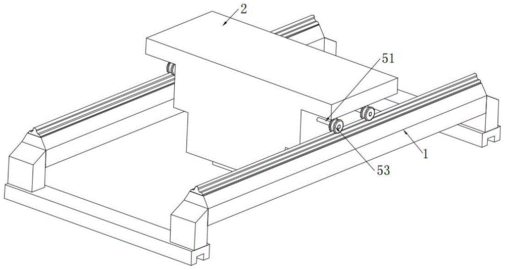
Fig. 1 is a schematic view of an electric hoist bridge crane according to the present invention;
fig. 2 is a perspective view of a traveling driving device of an electric hoist bridge crane according to the present invention;
FIG. 3 is a sectional view of a mounting block structure of an electric hoist bridge crane according to the present invention;
fig. 4 is a perspective view of a second transmission shaft structure of the electric hoist bridge crane according to the present invention;
FIG. 5 is a perspective view of a winding roller structure of an electric hoist bridge crane according to the present invention;
fig. 6 is a perspective view of a micro cylinder structure of an electric hoist bridge crane according to the present invention;
fig. 7 is a perspective view of a mounting shaft structure of an electric hoist bridge crane according to the present invention;
fig. 8 is a perspective view of a mounting sleeve structure of an electric hoist bridge crane according to the present invention;
fig. 9 is a structural sectional view of an operating panel of the electric hoist bridge crane according to the present invention;
fig. 10 is a sectional view of a connecting sleeve structure of an electric hoist bridge crane according to the present invention;
fig. 11 is an enlarged structural view of a portion a in fig. 4 of the electric hoist bridge crane according to the present invention.
In the figure: 1. supporting the guide rail; 2. mounting blocks; 3. a first mounting cavity; 4. a second mounting cavity; 5. a double-shaft motor; 51. a first drive shaft; 52. a second transmission shaft; 53. a traveling wheel; 54. a belt pulley; 6. installing a shaft; 61. a winding roller; 62. a hauling rope; 63. lifting the lifting hook; 64. an annular chute; 65. connecting a bearing; 66. connecting sleeves; 67. a first connection port; 68. a third connection port; 69. a micro cylinder; 610. an interface; 7. a drive motor; 71. installing a sleeve; 72. a first meshing disc; 73. a second meshing disk; 74. an operation panel; 75. an annular groove; 76. a connecting frame; 77. a first link; 78. a swing plate; 79. adjusting the motor; 710. a first mounting port; 711. a second mounting opening; 712. a first drive gear; 713. a second drive gear; 8. mounting a plate; 81. mounting grooves; 82. a guide wheel; 83. a guide groove; 84. a second connection port; 85. a rubber strip.
Detailed Description
The technical solutions in the embodiments of the present invention will be clearly and completely described below with reference to the drawings in the embodiments of the present invention, and it is obvious that the described embodiments are only a part of the embodiments of the present invention, and not all of the embodiments.
Referring to fig. 1-11, an electric hoist bridge crane includes support rails 1, and two support rails 1's upper surface is provided with installation piece 2, and first installation cavity 3 and second installation cavity 4 have been seted up respectively to the inner wall of installation piece 2, and the inner wall of first installation cavity 3 is provided with the walking drive device who is used for driving installation piece 2 reciprocating motion about on support rails 1, and the inner wall of second installation cavity 4 is provided with the intelligent hoisting accessory that is used for lifting by crane the material that needs to lift by crane.
As shown in fig. 1 to 4, the walking driving device includes a dual-shaft motor 5, in order to drive two first transmission shafts 51 to rotate synchronously, so that the two first transmission shafts 51 are fixedly connected to the two main shafts of the dual-shaft motor 5, and the first transmission shafts 51 are fixedly connected to the inner walls of the two ends of the first installation cavity 3 through bearings and extend to the outer surface of the installation block 2, so that the first transmission shafts 51 extend to the outside of the installation block 2, further, in order to increase the stability of the walking driving device, a second transmission shaft 52 is fixedly connected to the inner wall of the first installation cavity 3 through bearings, further, walking wheels 53 are fixedly connected to one ends of the two first transmission shafts 51 and the two ends of the second transmission shaft 52, so that the walking wheels 53 roll on the support rail 1 to drive the installation block 2 to move.
Through setting up the travel driving device, control double-shaft motor 5 drives two first transmission shafts 51 and rotates, and drive second transmission shaft 52 through the transmission of belt pulley 54 with the belt and rotate, and then drive walking wheel 53 and remove on support rail 1, corotation or the reversal through control double-shaft motor 5 make installation piece 2 remove left or right on support rail 1, reached through double-shaft motor 5 drive first transmission shaft 51 and second transmission shaft 52, and then the effect of the stationarity when increasing installation piece 2 and removing.
In order to drive two first transmission shafts 51 and second transmission shaft 52 to carry out synchronous motion, belt pulley 54 is all fixedly sleeved on the outer surfaces of the two first transmission shafts 51 and the second transmission shaft 52, and every two belt pulleys 54 are connected through belt transmission, so that the rotation of the first transmission shaft 51 is transmitted to the second transmission shaft 52, the first transmission shaft 51 and the second transmission shaft 52 are driven to rotate through the cooperation between the belt pulley 54 and the belt, and further the walking wheels 53 are driven to move on the support guide rail 1.
Further, the walking wheels 53 are in contact with the outer surface of the upper end of the support guide rail 1, so that the walking wheels 53 roll on the support guide rail 1 to drive the installation block 2 to move on the support guide rail 1, and the walking wheels 53 are in contact with the support guide rail 1 to cooperate with the rotation of the walking wheels 53 to drive the installation block 2 to move on the support guide rail 1.
As shown in fig. 2-8 and fig. 10-11, the intelligent hoisting device includes two sets of hoisting mechanisms, a state adjusting mechanism and a guiding mechanism, the hoisting mechanism includes a mounting shaft 6, in order to mount the winding roller 61, the winding roller 61 is fixedly sleeved on the outer surface of the mounting shaft 6, further, a traction rope 62 is wound on the outer surface of the winding roller 61, a lifting hook 63 is mounted at the tail end of the traction rope 62 through a connecting fastener, the traction rope 62 is received and released through the rotation of the winding roller 61, and further, the lifting hook 63 is controlled to ascend and descend, further, in order to fix the mounting shaft 6 in the second mounting cavity 4, annular chutes 64 are formed on the outer surfaces of both ends of the mounting shaft 6, a connecting bearing 65 is slidably sleeved on the inner wall of the annular chute 64, further, a connecting sleeve 66 is fixedly sleeved on the outer ring of the connecting bearing 65, and the connecting sleeve 66 is mounted through the connecting bearing 65, so that the connecting sleeve 66 does not hinder the operation effect of the mounting shaft 6 in the rotating process.
In order to connect the connecting sleeve 66 and the second installation cavity 4, the inner walls of the two ends of the second installation cavity 4 are respectively provided with a first connecting port 67, so that the outer surface of the connecting sleeve 66 is in threaded connection with the inner wall of the first connecting port 67, and the installation shaft 6 is fixed on the inner wall of the second installation cavity 4, and further, after the connecting sleeve 66 is connected with the first connecting port 67, the rotation of the installation shaft 6 does not loosen between the connecting sleeve 66 and the first connecting port 67, further, in order to prevent the winding roller 61 which does not work from rotating due to self gravity, the inner wall of one side of the second installation cavity 4 is respectively provided with third connecting ports 68 which are distributed in an annular array, and the inner walls of the plurality of third connecting ports 68 are respectively and fixedly connected with a micro cylinder 69, further, in order to connect the micro cylinder 69 and the winding roller 61, the insertion port 610 is formed on the surface of one end of the winding roller 61, and the outer surface of a pneumatic rod of the micro cylinder 69 is movably inserted into and connected with the inner wall of the insertion port 610, the connecting sleeve 66 is connected with the first connecting port 67 through threaded connection, the installation shaft 6, and the installation shaft 6 is convenient to be inserted into and is not driven by the fixing port 610 and the limiting roller 61.
As shown in fig. 2-5 and fig. 7-10, the state adjusting mechanism includes a driving motor 7, in order to control the mounting sleeve 71 to slide on the main shaft of the driving motor 7, the mounting sleeve 71 is movably sleeved on the surface of the main shaft of the driving motor 7, further, a first meshing disk 72 and a second meshing disk 73 are respectively fixedly sleeved on the outer surfaces of the two ends of the mounting sleeve 71, and by providing the hoisting mechanism, the purpose of mounting the connecting sleeve 66 through the connecting bearing 65 is achieved, so that the connecting sleeve 66 does not hinder the operation of the mounting shaft 6 in the rotating process, the driving motor 7 is controlled to drive the mounting sleeve 71 to rotate, and further the first meshing disk 72 and the second meshing disk 73 are driven to rotate, and further the driving gear meshed with the first meshing disk 72 or the second meshing disk 73 is driven to rotate, and further the corresponding mounting shaft 6 is driven to rotate, and the winding roller 61 is controlled to wind and unwind the traction rope 62, so as to further stably hoist the workpiece, and facilitate the mounting shaft 6 to be mounted and demounted.
Further, in order to control the movement of the first engaging disk 72 and the second engaging disk 73, an operation disk 74 is fixedly connected to the outer surface of the middle portion of the mounting sleeve 71, and annular grooves 75 are respectively formed in the surfaces of the two ends of the operation disk 74, a connecting frame 76 movably clamped with the inner wall of the annular groove 75 is connected to the edge of the operation disk 74 in a sliding and clamping manner, in order to connect the connecting frame 76 and the swinging plate 78, a first connecting rod 77 is fixedly connected to the upper surface of the connecting frame 76, further, a swinging plate 78 is rotatably sleeved on the outer surface of the first connecting rod 77, the connecting frame 76 and the swinging plate 78 are connected through the first connecting rod 77, and the swinging plate 78 can drive the connecting frame 76 to move.
In order to drive the operation panel 74 to move, an adjusting motor 79 is arranged above the swinging plate 78, further, the outer surface of a main shaft of the adjusting motor 79 is fixedly connected with the upper surface of one end of the swinging plate 78, the swinging plate 78 is driven by the adjusting motor 79, a first mounting port 710 for mounting the driving motor 7 is arranged on the inner wall of one end of the second mounting cavity 4, a second mounting port 711 for mounting the adjusting motor 79 is arranged on the inner top wall of the second mounting cavity 4, the adjusting motor 79 is mounted through the second mounting port 711, and the driving motor 7 is mounted through the first mounting port 710.
In order to drive the mounting shafts 6 through the first meshing disc 72 and the second meshing disc 73, a first driving gear 712 and a second driving gear 713 are fixedly connected to outer surfaces of one ends of the two mounting shafts 6 respectively, and the first driving gear 712 and the second driving gear 713 are arranged in a staggered manner, further, the first meshing disc 72 is in meshing transmission with the first driving gear 712, the second meshing disc 73 is in meshing transmission with the second driving gear 713, and the driving motor 7 is controlled through the position adjustment of the first meshing disc 72 and the second meshing disc 73 to simultaneously control the rotation of the two mounting shafts 6 or control the rotation of one of the mounting shafts 6.
As shown in fig. 3-4 and 11, the guiding mechanism includes a mounting plate 8, in order to guide the traction rope 62, two symmetrically distributed mounting grooves 81 are formed on an inner wall of the mounting plate 8, guide wheels 82 are movably hinged to inner walls of two sides of the mounting groove 81 through pin shafts, further, in order to increase contact and friction between the guide wheels 82 and the traction rope 62, a guide groove 83 is formed on an outer surface of a middle portion of the guide wheel 82, second connection ports 84 distributed in an annular array are formed on an inner wall of the guide groove 83, and a rubber strip 85 is fixedly connected to an inner wall of each second connection port 84, so that a circular guide port is formed between the two guide grooves 83 to guide the traction rope 62 by matching the two guide wheels 82, and the rubber strip 85 is added in the second connection port 84 to increase the effect of friction when the guide wheels 82 contact with the traction rope 62.
Through setting up state adjustment mechanism, reached through the position of the first meshing dish 72 of control mounting sleeve 71 on driving motor 7 main shaft sliding adjustment and second meshing dish 73, the corresponding installation axle 6 of meshing state control between first meshing dish 72 and first drive gear 712 and second meshing dish 73 and the second drive gear 713 is rotatory, and then can drive hoisting mechanism through same drive unit, carry out accurate quick intelligent control to intelligent hoisting accessory's drive state and object, and then reduce the time of the regulation and control of the drive state of intelligent hoisting accessory, the effect of the work efficiency of increase hoist.
The working principle is as follows: when the mounting block 2 is required to move on the support guide rail 1, the double-shaft motor 5 is controlled to start to drive the two first transmission shafts 51 to rotate, the belt pulley 54 and the belt are used for driving the second transmission shaft 52 to rotate, the travelling wheels 53 are further driven to move on the support guide rail 1, and the mounting block 2 is driven to move leftwards or rightwards on the support guide rail 1 by controlling the forward rotation or reverse rotation of the double-shaft motor 5;
when two groups of hoisting mechanisms need to be controlled to operate simultaneously, the adjusting motor 79 is controlled to drive the swinging plate 78 to rotate to be overlapped with the operating panel 74, the connecting frame 76 slides in the annular groove 75 while the swinging plate 78 moves, the first meshing disc 72 and the second meshing disc 73 connected with the mounting sleeve 71 are driven to be respectively meshed with the first driving gear 712 and the second driving gear 713, then the adjusting motor 79 is controlled to stop, then the driving motor 7 is controlled to drive the mounting sleeve 71 to rotate, further the first meshing disc 72 and the second meshing disc 73 are driven to rotate, the first driving gear 712 and the second driving gear 713 are driven to rotate through the meshing of the first meshing disc 72 and the second meshing disc 73 with the first driving gear 712 and the second driving gear 713, further the two mounting shafts 6 are driven to rotate, and further the two winding rollers 61 are controlled to synchronously rotate to synchronously receive and release the corresponding traction ropes 62;
when one of the hoisting mechanisms needs to run and the other hoisting mechanism needs to stop, the adjusting motor 79 is controlled to drive the swinging plate 78 to rotate to form a 30-degree angle with the left or right included angle between the swinging plate 78 and the operation disc 74, the connecting frame 76 slides in the annular groove 75 while the swinging plate 78 moves, the first meshing disc 72 connected with the mounting sleeve 71 is driven to be meshed with the first driving gear 712 or the second meshing disc 73 is driven to be meshed with the second driving gear 713, then the adjusting motor 79 is controlled to stop, and then the driving motor 7 is controlled to drive the mounting sleeve 71 to rotate so as to drive the first meshing disc 72 and the second meshing disc 73 to rotate;
under the condition, when the first meshing disc 72 is meshed with the first driving gear 712, the second meshing disc 73 is not meshed with the second driving gear 713, or when the second meshing disc 73 is meshed with the second driving gear 713, the first meshing disc 72 is not meshed with the first driving gear 712, so that the first driving gear 712 or the second driving gear 713 is driven to rotate, the corresponding mounting shaft 6 is driven to rotate, and one of the winding rollers 61 is controlled to rotate to wind and unwind the corresponding traction rope 62.
The above description is only for the preferred embodiment of the present invention, but the scope of the present invention is not limited thereto, and any person skilled in the art should be considered to be within the technical scope of the present invention, and the technical solutions and the inventive concepts thereof according to the present invention should be equivalent or changed within the scope of the present invention.