CN115180378A - Automatic overturning method for circular part - Google Patents
Automatic overturning method for circular part Download PDFInfo
- Publication number
- CN115180378A CN115180378A CN202210939842.8A CN202210939842A CN115180378A CN 115180378 A CN115180378 A CN 115180378A CN 202210939842 A CN202210939842 A CN 202210939842A CN 115180378 A CN115180378 A CN 115180378A
- Authority
- CN
- China
- Prior art keywords
- lifting
- circular part
- clamping
- power source
- lifting platform
- Prior art date
- Legal status (The legal status is an assumption and is not a legal conclusion. Google has not performed a legal analysis and makes no representation as to the accuracy of the status listed.)
- Granted
Links
- 238000000034 method Methods 0.000 title claims abstract description 28
- 230000007246 mechanism Effects 0.000 claims abstract description 153
- 230000007306 turnover Effects 0.000 claims abstract description 14
- 230000005540 biological transmission Effects 0.000 claims description 74
- 238000009434 installation Methods 0.000 claims description 19
- 230000000712 assembly Effects 0.000 claims description 12
- 238000000429 assembly Methods 0.000 claims description 12
- 239000003638 chemical reducing agent Substances 0.000 claims description 11
- 230000009467 reduction Effects 0.000 claims description 4
- 230000001360 synchronised effect Effects 0.000 claims description 3
- 230000000149 penetrating effect Effects 0.000 claims description 2
- 230000008569 process Effects 0.000 abstract description 7
- 239000011521 glass Substances 0.000 abstract 1
- 230000033001 locomotion Effects 0.000 description 9
- 238000004146 energy storage Methods 0.000 description 7
- 239000000463 material Substances 0.000 description 5
- 230000000694 effects Effects 0.000 description 4
- 238000007599 discharging Methods 0.000 description 3
- 238000004519 manufacturing process Methods 0.000 description 3
- 230000003287 optical effect Effects 0.000 description 3
- 238000006243 chemical reaction Methods 0.000 description 2
- 238000010586 diagram Methods 0.000 description 2
- 230000004048 modification Effects 0.000 description 2
- 238000012986 modification Methods 0.000 description 2
- 238000010248 power generation Methods 0.000 description 2
- 208000012260 Accidental injury Diseases 0.000 description 1
- OKTJSMMVPCPJKN-UHFFFAOYSA-N Carbon Chemical compound [C] OKTJSMMVPCPJKN-UHFFFAOYSA-N 0.000 description 1
- 230000002457 bidirectional effect Effects 0.000 description 1
- 229910052799 carbon Inorganic materials 0.000 description 1
- 239000000428 dust Substances 0.000 description 1
- 230000003028 elevating effect Effects 0.000 description 1
- 238000005516 engineering process Methods 0.000 description 1
- 230000007613 environmental effect Effects 0.000 description 1
- 230000006872 improvement Effects 0.000 description 1
- 208000014674 injury Diseases 0.000 description 1
- 238000012423 maintenance Methods 0.000 description 1
- 238000000053 physical method Methods 0.000 description 1
- 230000001681 protective effect Effects 0.000 description 1
- 239000007787 solid Substances 0.000 description 1
Images




Classifications
-
- B—PERFORMING OPERATIONS; TRANSPORTING
- B65—CONVEYING; PACKING; STORING; HANDLING THIN OR FILAMENTARY MATERIAL
- B65G—TRANSPORT OR STORAGE DEVICES, e.g. CONVEYORS FOR LOADING OR TIPPING, SHOP CONVEYOR SYSTEMS OR PNEUMATIC TUBE CONVEYORS
- B65G47/00—Article or material-handling devices associated with conveyors; Methods employing such devices
- B65G47/22—Devices influencing the relative position or the attitude of articles during transit by conveyors
- B65G47/24—Devices influencing the relative position or the attitude of articles during transit by conveyors orientating the articles
- B65G47/248—Devices influencing the relative position or the attitude of articles during transit by conveyors orientating the articles by turning over or inverting them
-
- B—PERFORMING OPERATIONS; TRANSPORTING
- B65—CONVEYING; PACKING; STORING; HANDLING THIN OR FILAMENTARY MATERIAL
- B65G—TRANSPORT OR STORAGE DEVICES, e.g. CONVEYORS FOR LOADING OR TIPPING, SHOP CONVEYOR SYSTEMS OR PNEUMATIC TUBE CONVEYORS
- B65G43/00—Control devices, e.g. for safety, warning or fault-correcting
-
- Y—GENERAL TAGGING OF NEW TECHNOLOGICAL DEVELOPMENTS; GENERAL TAGGING OF CROSS-SECTIONAL TECHNOLOGIES SPANNING OVER SEVERAL SECTIONS OF THE IPC; TECHNICAL SUBJECTS COVERED BY FORMER USPC CROSS-REFERENCE ART COLLECTIONS [XRACs] AND DIGESTS
- Y02—TECHNOLOGIES OR APPLICATIONS FOR MITIGATION OR ADAPTATION AGAINST CLIMATE CHANGE
- Y02E—REDUCTION OF GREENHOUSE GAS [GHG] EMISSIONS, RELATED TO ENERGY GENERATION, TRANSMISSION OR DISTRIBUTION
- Y02E60/00—Enabling technologies; Technologies with a potential or indirect contribution to GHG emissions mitigation
- Y02E60/16—Mechanical energy storage, e.g. flywheels or pressurised fluids
Landscapes
- Engineering & Computer Science (AREA)
- Mechanical Engineering (AREA)
- Specific Conveyance Elements (AREA)
Abstract
The invention discloses an automatic overturning method of a round part, which comprises the following steps: s1, placing a round part on a jacking mechanism; s2, driving the circular part clamping mechanism and the turnover power mechanism to move to the upper part of the lifting platform by the travelling mechanism; s3, lifting a lifting platform of the jacking mechanism; s4, clamping the round part; s5, turning the glass panel up and down for 180 degrees; s6, the jacking mechanism ascends again to support the overturned round part; and loosening the round part. According to the invention, the circular part clamping mechanism is used for clamping a part, the circular part clamping mechanism is moved to the position above the jacking mechanism through the first power mechanism, the circular part is positioned between the clamping units, the part is clamped through the clamping units, the circular part clamping mechanism and the part are vertically turned for 180 degrees through the power mechanism, and then the part is placed on the jacking mechanism, so that the part is transferred to the next process by a manipulator, the continuous turning of the part is realized, the whole turning process does not need manual auxiliary operation, and the turning efficiency is improved.
Description
Technical Field
The invention relates to the technical field of assembly of flywheel energy storage systems, in particular to an automatic overturning method for a circular part.
Background
The flywheel energy storage system stores energy by adopting a physical method, and realizes the mutual conversion and storage between electric energy and mechanical kinetic energy of a high-speed running flywheel through an electric/power generation mutual-inverse type bidirectional motor. The flywheel energy storage system has the advantages of high energy density, high conversion rate of electric energy and mechanical energy, high charging speed, no maintenance, low carbon, environmental protection and the like, and is applied to the fields of aerospace, power grid peak shaving, wind power generation and the like.
The flywheel energy storage battery (i.e. the flywheel body) is the core part of the flywheel energy storage system, and comprises a vacuum container with an upper cover plate and a lower cover plate, a flywheel installed in the vacuum container, and a rotor (comprising a motor rotor and an armature plate) and a backing ring (a plurality of rotors and backing rings are respectively arranged in an alternating manner. The assembly process of the flywheel body is to press fit the main shaft into an inner hole of the flywheel and seal one end part of the vacuum container; then the vacuum container and the flywheel are respectively turned over for 180 degrees to finish the assembly of the flywheel, the main shaft and the vacuum container, then the backing ring and the rotor are installed in an alternate assembly mode, and finally the vacuum container is sealed. It can be seen that the turning over of the flywheel and vacuum vessel is one of the necessary procedures.
With the rapid development of automation technology, the flywheel energy storage system is gradually transformed to a high-efficiency, automatic and intelligent assembly mode through manual assembly, a large number of multi-axis robots or truss manipulators are put into the assembly production line of the flywheel energy storage system, and the multi-axis robots or the truss manipulators are utilized to realize the loading, unloading, carrying, assembling and the like of all parts (a rotor, a flywheel, a backing ring and a vacuum container are all round parts with larger diameters) in a flywheel body. However, the current production line does not have a turning apparatus for turning over the vacuum vessel and the flywheel. In actual production, manual assistance is often needed for overturning, so that many manual interventions exist, the risk of part falling exists, the safety is low, the situation of accidental injury exists, and the overturning efficiency is low; in addition, round parts such as vacuum vessels are often heavy and difficult to grip, making them difficult to turn.
Disclosure of Invention
In view of the above, the invention provides an automatic turning method for a circular part, which utilizes a circular part clamping mechanism and a turning power mechanism to realize automatic turning of the circular part during turning, utilizes a jacking mechanism to perform feeding and discharging, realizes automatic feeding, turning and discharging of the part, improves turning efficiency and safety, and realizes full-automatic assembly of a flywheel body to lay a foundation.
In order to realize the purpose, the invention adopts the following technical scheme:
the automatic overturning method of the round part comprises the following steps:
s1, placing a round part to be turned over on a lifting table of a jacking mechanism; the lifting platform is provided with a first feeding height and a second feeding height, the first feeding height is lower than the second feeding height, and the second feeding height is lower than the height of the circular part clamping mechanism;
s2, sending a forward command to a travelling mechanism, and driving the circular part clamping mechanism and the overturning power mechanism to move above the lifting table by the travelling mechanism; the circular part clamping mechanism is provided with at least two pairs of clamping units in an opening and closing state, and the at least two pairs of clamping units are vertically spaced to vertically clamp the circular part;
s3, the control system controls the lifting platform of the jacking mechanism to ascend from the first feeding height to the second feeding height, so that the circular part is located between at least two pairs of clamping units;
s4, after the lifting platform rises to the proper position, the control system sends a clamping instruction to the circular part clamping mechanism, so that the clamping units move towards the circular part, and the clamping units are closed and clamp the circular part;
s5, the control system controls the lifting platform of the jacking mechanism to descend and reset to a first feeding height, and space is provided for overturning the round part; after the lifting platform is reset, the control system controls a horizontal power shaft of the turning power mechanism to rotate 180 degrees, so that the circular part clamping mechanism and the circular part are turned 180 degrees up and down simultaneously;
s6, after the round part is turned for 180 degrees, the control system sends a lifting instruction to the jacking mechanism, so that the lifting platform is lifted to a second feeding height again to support the turned round part; after the lifting platform rises to a proper position, the control system sends an opening blanking instruction to the circular part clamping mechanism to loosen the circular part, and the lifting platform is used for supporting the circular part;
s7, sending a reset instruction to the jacking mechanism and the walking mechanism by the control system, enabling a lifting platform of the jacking mechanism to descend and reset, enabling the circular part clamping mechanism to horizontally move backwards along the rack to an initial position, and taking away the overturned circular part by a worker or a robot;
and repeating the steps S1-S7, and overturning the circular parts to be overturned in sequence.
In the above technical scheme: according to the invention, the circular part clamping mechanism is rotatably arranged on the moving structure which runs along the rack, the circular part clamping mechanism is moved to the position above the jacking mechanism through the first power mechanism, the lifting table is lifted to enable the circular part to be positioned between the clamping units, the circular part is clamped through the clamping units, the circular part clamping mechanism and the circular part are turned over by 180 degrees up and down through the power mechanism, and then the circular part is placed on the jacking mechanism after turning over, so that the circular part is transferred to the next process by a manipulator, the continuous turning over of the circular part is realized, no manual auxiliary operation is needed in the whole turning over process, and the turning over efficiency is improved.
Preferably, the round part travelling mechanism, the turning power mechanism and the round part clamping mechanism are all arranged on a moving structure on the frame; the walking mechanism is an air cylinder or a hydraulic cylinder, or a gear rack transmission pair, a chain transmission pair, a synchronous belt transmission pair or a transmission lead screw driven by a walking power source; the walking power source is a motor or a motor reducer, or a gear transmission pair with a reduction ratio.
In actual installation, the traveling mechanism may be any of those described above. According to the layout and the operation space of a workshop, a gear-rack transmission pair (provided with a gear and a rack which are meshed with each other) driven by a walking power source is preferably selected, the gear is fixed at the power output end of the walking power source, and the rack is horizontally arranged on the rack;
in step S2, the step of moving the circular part clamping mechanism and the tilter power mechanism to the position above the lifting table by the traveling mechanism is specifically: the walking power source receives a forward instruction sent by the control system, the walking power source drives the gear to rotate, and the gear is meshed with the rack to drive the circular part clamping mechanism and the turning power mechanism on the moving structure to move to the position above the lifting platform;
in step S7, the horizontally moving the circular part clamping mechanism backward along the rack to the initial position specifically includes: the walking power source receives a reset instruction sent by the control system, the walking power source drives the gear to rotate in the opposite direction, the gear is meshed with the rack on the rack to enable the gear to move linearly along the rack, and the gear drives the circular part clamping mechanism to reset through the moving structure.
Preferably, the jacking mechanism comprises a lifting power source, a lifting transmission assembly in transmission connection with the lifting power source, and a lifting frame fixed on the lifting transmission assembly, and the lifting table is horizontally erected on the lifting frame;
in step S3, the control system controls the lifting platform of the jacking mechanism to ascend from the first loading height to the second loading height, and includes: the control system sends a lifting instruction to the lifting power source, and the lifting power source drives the lifting frame and the lifting platform to rise to a second feeding height through the lifting transmission assembly;
in step S5, the control system controls the lifting platform of the jacking mechanism to descend and reset to the initial height, and includes: the control system sends a descending instruction to the lifting power source, the lifting power source rotates in the opposite direction, and the lifting frame and the lifting platform are driven by the lifting transmission assembly to descend and reset to the first feeding height.
More preferably, the lifting transmission assemblies are a pair, and the lifting transmission assemblies are chain transmission pairs, belt transmission pairs, transmission lead screws or lifting shafts; the lifting frame is provided with a frame body and lifting seats arranged on two sides of the frame body, and the lifting seats are connected with a lifting transmission assembly; the lifting platform is erected on the frame body between the two lifting seats through a plurality of positioning shafts.
During actual installation, the lifting transmission assembly preferably selects a chain transmission pair with strong bearing property, the two chain transmission pairs are in transmission connection through a transmission shaft, and the lifting frame is erected on the chain transmission pair to ensure stable lifting of the lifting frame; in addition, still set up in the frame with vice supporting mounting bracket of chain drive, chain drive is vice installs on the mounting bracket, and has the direction optical axis for the crane direction on the mounting bracket, further ensures the motion accuracy and the stability of crane, realizes the steady lift of circular part's high accuracy.
Preferably, the turning power mechanism comprises a turning power source arranged on the moving structure, and a power end of the turning power source is fixedly connected with one rotating shaft of the circular part clamping mechanism through a coupler; wherein, the overturning power source is a motor, a motor reducer with a reduction ratio or a gear transmission mechanism. In actual installation, the optimal turning power source is preferably a motor reducer.
Preferably, the circular part clamping mechanism further comprises a roll-over stand, wherein the roll-over stand comprises a pair of vertically arranged installation base bodies and a connecting beam for connecting the two installation base bodies together; at least two first power sources which are arranged at intervals up and down are installed on each installation base body, and the power end of each first power source is provided with one clamping unit.
More preferably, a power end of the first power source is fixedly connected with a first pushing handle, and the clamping unit is fixedly connected with the first pushing handle; a plurality of groups of guide pairs are arranged between the first pushing hand and the mounting base body, each group of guide pairs comprises a linear guide sleeve arranged on the mounting base body and a first guide rod horizontally arranged on the first pushing hand, and the first guide rod is arranged on the linear guide sleeve in a penetrating mode in a sliding mode.
Each clamping unit is matched with a first power source to ensure the clamping force; a guide pair is arranged between the clamping unit and the mounting base body, so that the high-precision movement of the clamping unit is realized, and the clamping effect is ensured.
Preferably, circular part fixture still includes by a plurality of supplementary centre gripping subassemblies, every be provided with two at least supplementary centre gripping subassemblies on the installation base member, supplementary clamping components includes the second power supply and sets up second holder on the second power supply, the vertical setting of second holder has with circular part's outer wall complex second arcwall face.
In the scheme, the second clamping piece is vertically arranged, so that the radial clamping of the circular part can be realized; the clamping unit can realize radial clamping, and the clamping unit is at least two pairs from top to bottom, acts on the upper portion and the lower portion of circular part respectively. The second clamping piece is matched with the clamping unit for use, so that the clamping stability is ensured.
More preferably, the auxiliary clamping assembly further comprises a second pushing handle driven by the second power source, and the second clamping piece is vertically arranged on the second pushing handle; at least two groups of guide assemblies are arranged between the second pushing hand and the mounting base body to ensure the movement precision and the clamping force of the second pushing hand.
Drawings
Fig. 1 is a schematic structural view of the automatic turnover device of the present invention.
Fig. 2 is a top view of fig. 1.
Fig. 3 is a schematic structural diagram of the jacking mechanism.
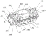
Fig. 4 is a schematic view of the circular part holding mechanism of the present invention.
Fig. 5 is a side view of fig. 4.
Fig. 6 is a state diagram after the vacuum vessel is turned upside down.
Detailed Description
The following describes embodiments of the present invention in detail with reference to the drawings, which are implemented on the premise of the technical solution of the present invention, and detailed embodiments and specific operation procedures are provided, but the scope of the present invention is not limited to the following embodiments.
It should be noted that the circular component in the embodiment of the present invention includes a disk-like component (such as a flywheel of a flywheel body), and further includes a cylindrical component (such as a vacuum container of the flywheel body).
The invention aims to provide an automatic overturning method of a circular part, and aims to solve the problems of more manual intervention, low automation degree, low overturning efficiency and potential safety hazard in a flywheel body assembly line.
The automatic turnover method of the round part adopts a special automatic turnover device. As can be seen from fig. 1 to 6, the automatic turnover device includes a frame 10, a jacking mechanism 20, a traveling mechanism 30, a circular part clamping mechanism 40, and a turnover power mechanism 50; wherein:
as shown in fig. 1-3, the rack 10 has a fixed frame 101 for carrying the circular part clamping mechanism 40, and a lower protective cover 102 (having a window for facilitating robot entering and exiting) covering the rack, so that the appearance is attractive and elegant, and the influence of dust in a workshop on each mechanism is reduced;
a pair of first slide rails 103 are arranged on a fixed frame of the rack 10 at intervals, and a moving structure is arranged on the first slide rails and provided with two moving seats 104; each first slide rail 103 is connected with a movable seat 104 through a first slide block, and two rotating shafts of the circular part clamping mechanism are rotatably arranged on the two movable seats, so that the circular part clamping mechanism is erected on the fixed frame.
As shown in fig. 1-3, the traveling mechanism 30 includes a traveling power source 301 (preferably, a motor reducer, but a motor may be used) fixed on one of the movable bases 104, a gear mounted on the traveling power source 301, and a rack 302 disposed on the frame 10, wherein the gear is engaged with the rack 302. Because the rack 302 is fixedly installed on the rack 10 and the gear is meshed with the rack 302, when the power shaft of the walking power source 301 rotates, the gear moves along the rack 302, so that the horizontal movement of the movable base 104 and the circular part clamping mechanism 40 is realized, and the clamping requirement of the circular part is met. During operation, the moving direction of the movable base 104 is adjusted by changing the rotation direction of the traveling power source 301.
Compared with a cylinder, a chain transmission mechanism and a belt transmission mechanism, the travelling mechanism disclosed by the invention utilizes the space of the rack as much as possible, and is compact in structure and small in occupied space. When the turnover mechanism works, the walking mechanism 30 provides horizontal reciprocating power for the circular part clamping mechanism 40 and the turnover power mechanism 50, and then turnover and resetting of the circular part clamping mechanism and the turnover power mechanism are achieved.
As shown in fig. 1-2, a turning power mechanism is mounted on the other movable base 104 of the frame, the turning power mechanism 50 includes a turning power source 501 (preferably, a motor reducer) fixedly connected to the movable base 104, and a power shaft of the turning power source 501 is in transmission connection with one rotating shaft 401 of the circular part clamping mechanism 40 through a coupler to provide turning power for the circular part.
As shown in fig. 1-3, the jacking mechanism 20 is disposed inside the frame 10, the jacking mechanism 20 includes a lifting power source 204, a lifting transmission assembly in transmission connection with the lifting power source 204, and a lifting frame 202 fixed on the lifting transmission assembly, four guide members (i.e., positioning shafts 203) are vertically disposed on the lifting frame 202, and the upper portion of the positioning shafts 203 has positioning heads matched with the lifting table 201, so that the lifting table 201 is horizontally mounted on the four positioning heads, thereby realizing positioning and mounting of the lifting table 201 and improving accuracy.
As shown in fig. 1-3, the lifting transmission assembly is a chain transmission pair 205 (the chain transmission pair can also replace a belt transmission pair or a synchronous belt transmission pair) which is vertically installed, and the chain transmission pair 205 is located at two end parts of the lifting frame 202; the two ends of the lifting frame 202 are provided with lifting seats 207, each lifting seat 207 is fixed with a chain of one of the chain transmission pairs 205, and lower chain wheels of the two chain transmission pairs 205 are connected together through a transmission shaft 206, so that the transmission connection of the lifting power source 204 and the lifting frame 202 and the stable lifting of the lifting frame are realized, and a foundation is laid for realizing the stable feeding and discharging of the round parts.
As shown in fig. 1-3, the jacking mechanism further comprises an installation frame for installing the chain transmission pair 205, the installation frame comprises a base 208 arranged below the lifting frame 202 and a top seat 209 arranged above the lifting frame 202, two ends of the transmission shaft 206 (horizontally installed) penetrate through a lower chain wheel of the chain transmission pair 205, each end of the transmission shaft 206 is rotatably arranged on the base 208 through a bearing seat, an upper chain wheel of each chain transmission pair 205 is rotatably arranged on the top seat 209 through a bearing seat, and the installation of the chain transmission pair 205 is realized.
As shown in fig. 1-3, in order to ensure the motion accuracy and stability of the lifting frame 202 and the lifting platform 201, two vertical guide optical axes 210 are further arranged between each pair of the base 208 and the top base 209 which correspond up and down, and the lifting base 207 is provided with a sliding bearing 211 matched with the guide optical axes 210.
As shown in fig. 1, the lifting power source 204 includes a chain transmission pair B driven by a first motor reducer, a driven gear of the chain transmission pair B is mounted on the transmission shaft 206 to realize transmission connection between the first motor reducer and the transmission shaft 206, and the lifting device has a compact structure, occupies a small space, has high operation precision, and realizes high-precision stable lifting of the lifting frame 202 and the lifting platform 201.
During actual installation, if the installation space permits, the lifting power source 204 may also directly select a motor reducer, and the output shaft of the motor reducer is connected to the transmission shaft 206. During actual installation, the lifting power source and the lifting transmission assembly can be replaced by a plurality of vertical air cylinders or hydraulic cylinders, and the lifting frame 202 can be stably lifted by the aid of the plurality of air cylinders or hydraulic cylinders acting simultaneously.
In a preferred embodiment of the invention: as shown in fig. 1-2, the lifting platform 201 has four limiting members (i.e., limiting seats 212) that are engaged with the edges of the circular parts, and the limiting seats 212 are located on the same circumference, so that the circular parts to be turned over can be placed in the limiting grooves surrounded by the limiting seats 212.
As shown in fig. 1-6, the circular part clamping mechanism 40 has a pair of rotating shafts 401 erected on the moving structure (the rotating shafts 401 can rotate relative to the moving structure), a roll-over stand, and two pairs of clamping units, the two rotating shafts 401 are respectively rotatably installed on the moving base 104 through a connecting assembly (i.e., a plurality of bearing blocks), one of the rotating shafts 401 is in transmission connection with the roll-over power mechanism 50, so as to realize transmission connection between the roll-over rotating mechanism 50 and the roll-over stand, and meet the roll-over requirement of the circular part clamping mechanism 40; every to the centre gripping unit have with circular part outer wall complex arc clamping face, realize the centre gripping dynamics of disc part, avoid dropping.
As shown in fig. 1-4, the roll-over stand includes a pair of mounting bases (i.e. vertically disposed bases 416) with the same structure, and the two bases 416 are connected to form a whole through two horizontally disposed connecting beams 402, so as to realize the integral roll-over of the circular part clamping mechanism 40.
As shown in fig. 4-6, the circular part clamping mechanism 40 includes a pair of clamping assemblies, one for each base 416. Each clamping assembly comprises two first power sources (preferably air cylinders, referred to as first air cylinders 403) which are arranged on the solid base 416 at intervals up and down, the end part of a piston rod of each first air cylinder 403 is fixedly connected with a first push handle 404, and a clamping unit for clamping the round part is arranged on each first push handle 404. During operation, the four first cylinders 403 of the two clamping assemblies simultaneously act to clamp and open the clamping units, so as to meet the clamping requirements of the circular parts. In addition, each clamping assembly is provided with two clamping units which are arranged at intervals up and down, and the clamping units of the two clamping assemblies are opposite to each other in pairs, so that the clamping of the upper position and the lower position of the round part is realized, the round part is ensured to be clamped, and the round part is prevented from falling in the overturning process.
As shown in fig. 4, two sets of guide pairs are disposed between each first pushing handle 404 and the base 416, each set of guide pair includes a linear guide sleeve 405 (preferably, a linear bearing seat) disposed on the base 416 and a first guide rod 406 horizontally disposed on the first pushing handle 404, the first guide rod 406 is slidably disposed on the linear guide sleeve 405, and the other end of each first guide rod 406 is fixed on the fixing seat 407, so as to ensure the movement precision of the first pushing handle 404, and further ensure the movement precision and stability of the clamping unit.
As shown in fig. 4 and 6, the clamping unit includes two first clamping blocks 408 horizontally disposed on the first pushing handle 404 (spaced apart), and the two first clamping blocks 408 are spaced apart (of course, only one first clamping block 408 with a longer length may be mounted during actual installation).
In the invention, each group of the first clamping blocks 408 positioned above acts on the upper part of the circular part, and each group of the first clamping blocks 408 positioned below acts on the lower part of the circular part, so that the stable clamping of the circular part is realized, and the clamping effect is good; in addition, each clamping unit corresponds to one first air cylinder, so that clamping force and clamping stability are ensured, and falling is avoided.
In a preferred embodiment of the invention: as shown in fig. 4-5, the circular part clamping mechanism 40 further includes two auxiliary clamping assemblies disposed opposite to each other, and two auxiliary clamping assemblies are disposed on each base 416, and spaced front and back on the base 416 and located at two sides of the clamping unit;
as shown in fig. 4-6, the auxiliary clamping assembly includes a second clamping member (i.e. a second clamping block 410) driven by a second cylinder 409 along a second power source (preferably, the cylinder), and the second clamping block 410 is vertically disposed and has a second arc-shaped surface matched with the outer wall of the circular part, so as to realize the axial clamping of the circular part. During operation, four vertical second grip blocks 410 act on circular component simultaneously, further ensure circular component's centre gripping effect, avoid dropping, improved the security.
In a preferred embodiment of the invention: as shown in fig. 4-6, a piston rod of the second cylinder 409 is fixedly connected with a vertical second pushing handle 411 (in a plate-shaped structure), the second clamping block 410 is fixed on the second pushing handle 411, and the second pushing handle provides an installation basis for the second clamping block.
As shown in fig. 4-6, two guiding assemblies are disposed between the base 416 and the first pushing handle 404, the guiding assemblies include a second guiding rod 412 horizontally disposed on the second pushing handle 411 and a guiding sleeve 413 fixed on the base 416, and the second guiding rod 412 is slidably disposed through the guiding sleeve 413.
In a more preferred embodiment of the invention: as shown in fig. 4-6, in order to further improve the structural stability of the circular part clamping mechanism 40 and the movement precision of the second pushing handle 411, a guide shaft 414 is further disposed between the second pushing handle 411 which is opposite to the left and right, two ends of the guide shaft 414 are respectively fixedly connected with a base 416, and the second pushing handle 411 is provided with linear guide seats 415 (preferably linear bearing seats) which are matched with the guide shaft 414 one by one. By adopting the scheme, the two bases 416 are connected together through the two connecting beams and the four guide shafts 414 which are arranged in a rectangular shape to form the turnover frame body, so that the structural strength, the stability and the bearing performance are improved. In addition, the linear guide holder 415 and the guide shaft 414 are matched with each other to have a guiding function, so that the movement precision of the second push handle 411 is improved, and the clamping stability is further ensured.
The automatic overturning method of the circular part comprises the following steps:
step S1, a six-axis robot is used for placing a round part to be turned over on a lifting table 201 of a jacking mechanism 20; the lifting platform 201 is provided with a first feeding height and a second feeding height, the first feeding height and the second feeding height are both located below the fixed frame 101, the first feeding height is lower than the second feeding height, and the first feeding height is matched with the six-axis robot, so that the robot can take materials and feed materials conveniently; the second feeding height corresponds to the circular part clamping mechanism, so that the material taking and the turned material placing are convenient to clamp;
step S2, after the part reaches a first loading position, the control system sends a forward instruction to the traveling mechanism 30, the traveling mechanism 30 drives the circular part clamping mechanism 40 and the overturning power mechanism 50 to move to the position above the lifting table 201, and the clamping center of the circular part clamping mechanism 40 is coaxial with the part below;
s3, the circular part clamping mechanism 40 is in place, and the control system controls the lifting platform 201 of the jacking mechanism 20 to ascend from a first feeding height to a second feeding height, so that the circular parts on the lifting platform 201 enter between the two pairs of clamping units from bottom to top;
step S4, after the lifting platform 201 is lifted to the right position, the control system sends a clamping instruction to the circular part clamping mechanism, piston rods of the four first air cylinders 403 and the four second air cylinders simultaneously extend outwards, the clamping units and the second clamping blocks which are symmetrically arranged enable the circular part to be stressed in a balanced manner, and the plurality of first air cylinders 403 and the plurality of second air cylinders 409 ensure clamping force and clamping effect;
step S5, after the part is clamped, the control system sends a reset instruction to the jacking mechanism 20 to enable the lifting table 201 to descend to a first feeding height, and space is provided for overturning the circular part;
after the lifting platform 201 is reset, the control system sends a turning instruction to the turning power mechanism 50, and the turning power mechanism 50 drives the circular part clamping mechanism 40 to turn 180 degrees integrally through the rotating shaft 401, so that 180-degree automatic turning of the parts is realized;
step S6, after the overturning is finished, the control system sends a lifting instruction to the jacking mechanism 20, so that the lifting 201 is lifted to a second feeding height again to support the overturned round part;
after the lifting platform 201 is in place, the control system sends out a blanking opening instruction to the circular part clamping mechanism, piston rods of the four first air cylinders 403 and the four second air cylinders 409 retract simultaneously, and the overturned part is placed on the lifting platform 201;
s7, a control system sends a reset instruction to the jacking mechanism 20 and the traveling mechanism 30, the lifting platform 201 of the jacking mechanism 20 descends and resets, and the traveling mechanism 30 drives the circular part clamping mechanism 40 to horizontally move backwards to an initial position along a first sliding rail, so that a material taking and feeding space is provided for a robot or a worker;
take the part after the upset away and deposit to the assigned position with the robot, on another part of treating the upset was arranged in elevating platform 201 with the reuse robot, realized the assembly line upset operation of circular part in batches, whole upset process need not artifical auxiliary operation, has improved upset efficiency, and labour saving and time saving.
In the description of the present invention, unless otherwise explicitly specified or limited, the terms "mounted", "connected" and "connected" as may be used herein are to be construed broadly, as being either a fixed connection, a releasable connection, or an integral connection; can be mechanically or electrically connected; either directly or indirectly through intervening media, or may be interconnected between two elements. The specific meanings of the above-mentioned terms in the present invention can be understood by those skilled in the art through specific situations.
Finally, it should be emphasized that the above-described embodiments are merely preferred embodiments of the present invention, and not limitations of the invention are intended to be imposed on the scope of the present invention, and although the invention has been described in detail with reference to the above-described embodiments, it will be apparent to those skilled in the art that modifications and equivalents may be made to the embodiments described in the foregoing embodiments without inventive faculty, or that equivalents may be substituted for some of the features. Therefore, any modification, equivalent replacement, improvement and the like made within the spirit and principle of the present invention should be included in the protection scope of the present invention.
Claims (10)
1. An automatic overturning method for a circular part is characterized by comprising the following steps:
s1, placing a round part to be turned over on a lifting table of a jacking mechanism; the lifting platform is provided with a first feeding height and a second feeding height, the first feeding height is lower than the second feeding height, and the second feeding height is lower than the height of the circular part clamping mechanism;
s2, sending a forward instruction to a traveling mechanism, and driving the circular part clamping mechanism and the turnover power mechanism to move to the upper part of the lifting platform by the traveling mechanism; the circular part clamping mechanism is provided with at least two pairs of clamping units in an opening and closing state, and the at least two pairs of clamping units are vertically spaced to vertically clamp the circular part;
s3, the control system controls the lifting platform of the jacking mechanism to ascend from the first feeding height to the second feeding height, so that the circular part is located between at least two pairs of clamping units;
s4, after the lifting platform rises to the proper position, the control system sends a clamping instruction to the circular part clamping mechanism, so that the clamping units move towards the circular part, and the clamping units are closed and clamp the circular part;
s5, the control system controls the lifting platform of the jacking mechanism to descend and reset to a first feeding height, and space is provided for overturning the round part; after the lifting platform is reset, the control system controls a horizontal power shaft of the turning power mechanism to rotate 180 degrees, so that the circular part clamping mechanism and the circular part are turned 180 degrees up and down simultaneously;
s6, after the round part is turned for 180 degrees, the control system sends a lifting instruction to the jacking mechanism, so that the lifting platform is lifted to a second feeding height again to support the turned round part; after the lifting platform rises to a proper position, the control system sends an opening blanking instruction to the circular part clamping mechanism to loosen the circular part, and the lifting platform is used for supporting the circular part;
s7, a control system sends a reset instruction to the jacking mechanism and the traveling mechanism to enable a lifting platform of the jacking mechanism to descend and reset, the circular part clamping mechanism horizontally moves backwards along the rack to an initial position, and the round part after overturning is taken away manually or by a robot;
and repeating the steps S1 to S7, and overturning the round part to be overturned in sequence.
2. The automatic turning method of a round part according to claim 1, characterized in that: the round part travelling mechanism, the overturning power mechanism and the round part clamping mechanism are all arranged on a moving structure on the frame;
the walking mechanism is an air cylinder or a hydraulic cylinder, or a gear rack transmission pair, a chain transmission pair, a synchronous belt transmission pair or a transmission lead screw driven by a walking power source, wherein the walking power source is a motor or a motor reducer, or a gear transmission pair with a reduction ratio.
3. The automatic turning method of a circular part according to claim 2, characterized in that: the walking mechanism is a gear and rack transmission pair driven by a walking power source, the walking power source is arranged on the moving structure, the gear and rack transmission pair is provided with a gear and a rack which are meshed with each other, the gear is fixed at the power output end of the walking power source, and the rack is horizontally arranged on the rack;
in step S2, the step of moving the circular part clamping mechanism and the tilter power mechanism to the position above the lifting table by the traveling mechanism is specifically: the walking power source receives a forward instruction sent by the control system, the walking power source drives the gear to rotate, and the gear is meshed with the rack to drive the circular part clamping mechanism and the turning power mechanism on the moving structure to move to the position above the lifting platform;
in step S7, the horizontally moving the circular part clamping mechanism backward along the rack to the initial position specifically includes: the walking power source receives a reset instruction sent by the control system, the walking power source drives the gear to rotate in the opposite direction, the gear is meshed with the rack on the rack to enable the gear to move linearly along the rack, and the gear drives the circular part clamping mechanism to reset through the moving structure.
4. The automatic turning method of a round part according to claim 1, characterized in that: the jacking mechanism comprises a lifting power source, a lifting transmission assembly in transmission connection with the lifting power source and a lifting frame fixed on the lifting transmission assembly, and the lifting platform is horizontally erected on the lifting frame;
in step S3, the control system controls the lifting platform of the jacking mechanism to ascend from the first loading height to the second loading height, and includes: the control system sends a lifting instruction to the lifting power source, and the lifting power source drives the lifting frame and the lifting platform to rise to a second feeding height through the lifting transmission assembly;
in step S5, the control system controls the lifting platform of the jacking mechanism to descend and reset to the initial height, and includes: the control system sends a descending instruction to the lifting power source, the lifting power source rotates in the opposite direction, and the lifting frame and the lifting platform are driven by the lifting transmission assembly to descend and reset to the first feeding height.
5. The automatic turning method of a circular part according to claim 4, characterized in that: the lifting transmission assemblies are a pair, and each lifting transmission assembly is a chain transmission pair, a belt transmission pair, a transmission screw rod or a lifting shaft;
the lifting frame is provided with a frame body and lifting seats arranged on two sides of the frame body, and the lifting seats are connected with a lifting transmission assembly; the lifting platform is erected on the frame body between the two lifting seats through a plurality of positioning shafts.
6. The automatic turning method of a round part according to claim 2, characterized in that: the turning power mechanism comprises a turning power source arranged on the moving structure, and a power end of the turning power source is fixedly connected with one rotating shaft of the round part clamping mechanism through a coupler;
the turning power source is a motor, or a motor reducer or a gear transmission mechanism with a reduction ratio.
7. The automatic turning method of a round part according to claim 2, characterized in that: the round part clamping mechanism further comprises a turnover frame, and the turnover frame comprises a pair of vertically arranged installation base bodies and a connecting beam for connecting the two installation base bodies together; at least two first power sources which are arranged at intervals up and down are installed on each installation base body, and the power end of each first power source is provided with one clamping unit.
8. The automatic turning method of a circular part according to claim 7, characterized in that: the power end of the first power source is fixedly connected with a first push handle, and the clamping unit is fixedly connected with the first push handle;
a plurality of groups of guide pairs are arranged between the first pushing handle and the mounting base body, each group of guide pairs comprises a linear guide sleeve arranged on the mounting base body and a first guide rod horizontally arranged on the first pushing handle, and the first guide rod is arranged on the linear guide sleeve in a penetrating mode in a sliding mode.
9. The automatic turning method of a round part according to claim 7, characterized in that: circular part fixture still includes by a plurality of supplementary centre gripping subassemblies, every be provided with two at least supplementary centre gripping subassemblies on the installation base member, supplementary clamping assembly includes the second power supply and sets up second holder on the second power supply, the vertical setting of second holder has with circular part's outer wall complex second arcwall face.
10. The automatic turning method of a circular part according to claim 8, characterized in that: the auxiliary clamping assembly further comprises a second pushing handle driven by the second power source, and the second clamping piece is vertically arranged on the second pushing handle; at least two groups of guide assemblies are arranged between the second pushing handle and the mounting base body.
Priority Applications (1)
| Application Number | Priority Date | Filing Date | Title |
|---|---|---|---|
| CN202210939842.8A CN115180378B (en) | 2022-08-05 | 2022-08-05 | Automatic overturning method for round part |
Applications Claiming Priority (1)
| Application Number | Priority Date | Filing Date | Title |
|---|---|---|---|
| CN202210939842.8A CN115180378B (en) | 2022-08-05 | 2022-08-05 | Automatic overturning method for round part |
Publications (2)
| Publication Number | Publication Date |
|---|---|
| CN115180378A true CN115180378A (en) | 2022-10-14 |
| CN115180378B CN115180378B (en) | 2023-09-26 |
Family
ID=83523245
Family Applications (1)
| Application Number | Title | Priority Date | Filing Date |
|---|---|---|---|
| CN202210939842.8A Active CN115180378B (en) | 2022-08-05 | 2022-08-05 | Automatic overturning method for round part |
Country Status (1)
| Country | Link |
|---|---|
| CN (1) | CN115180378B (en) |
Cited By (1)
| Publication number | Priority date | Publication date | Assignee | Title |
|---|---|---|---|---|
| CN116354076A (en) * | 2023-03-07 | 2023-06-30 | 江西江铃底盘股份有限公司 | Automatic lifting and vertical overturning mechanism for intelligent production of axle housing body and application method thereof |
Citations (5)
| Publication number | Priority date | Publication date | Assignee | Title |
|---|---|---|---|---|
| CN109178867A (en) * | 2018-06-21 | 2019-01-11 | 长兴溪谷智能装备有限公司 | A kind of middle large density battery tipper |
| CN109292411A (en) * | 2018-12-03 | 2019-02-01 | 燕山大学 | A turning mechanism based on wheel hub processing equipment |
| CN113581808A (en) * | 2021-06-26 | 2021-11-02 | 山东省智能机器人应用技术研究院 | Caterpillar track link turnover mechanism |
| CN113601462A (en) * | 2021-08-11 | 2021-11-05 | 北京机科国创轻量化科学研究院有限公司 | Sand mold assembly workbench suitable for non-mold composite forming process |
| CN215158750U (en) * | 2021-07-09 | 2021-12-14 | 济南瑞欧博自动化设备有限公司 | A flip mechanism based on solar cells |
-
2022
- 2022-08-05 CN CN202210939842.8A patent/CN115180378B/en active Active
Patent Citations (5)
| Publication number | Priority date | Publication date | Assignee | Title |
|---|---|---|---|---|
| CN109178867A (en) * | 2018-06-21 | 2019-01-11 | 长兴溪谷智能装备有限公司 | A kind of middle large density battery tipper |
| CN109292411A (en) * | 2018-12-03 | 2019-02-01 | 燕山大学 | A turning mechanism based on wheel hub processing equipment |
| CN113581808A (en) * | 2021-06-26 | 2021-11-02 | 山东省智能机器人应用技术研究院 | Caterpillar track link turnover mechanism |
| CN215158750U (en) * | 2021-07-09 | 2021-12-14 | 济南瑞欧博自动化设备有限公司 | A flip mechanism based on solar cells |
| CN113601462A (en) * | 2021-08-11 | 2021-11-05 | 北京机科国创轻量化科学研究院有限公司 | Sand mold assembly workbench suitable for non-mold composite forming process |
Cited By (2)
| Publication number | Priority date | Publication date | Assignee | Title |
|---|---|---|---|---|
| CN116354076A (en) * | 2023-03-07 | 2023-06-30 | 江西江铃底盘股份有限公司 | Automatic lifting and vertical overturning mechanism for intelligent production of axle housing body and application method thereof |
| CN116354076B (en) * | 2023-03-07 | 2023-12-22 | 江西江铃底盘股份有限公司 | Automatic lifting and vertical overturning mechanism for intelligent production of axle housing body and application method thereof |
Also Published As
| Publication number | Publication date |
|---|---|
| CN115180378B (en) | 2023-09-26 |
Similar Documents
| Publication | Publication Date | Title |
|---|---|---|
| CN103332487B (en) | Tire sorting equipment and method for sorting | |
| CN103894872A (en) | 180-degree overturning and deflecting machine for large workpieces | |
| CN102601120A (en) | Automatic roll changing and adjusting device of rolling mill and operation method of automatic roll changing and adjusting device | |
| CN217675293U (en) | Disc piece overturning device for flywheel energy storage system assembly production line | |
| CN113649994B (en) | Robot for mounting wind power blade stud | |
| CN111482738A (en) | Multidirectional adjustment welding process for realizing series connection of positive electrodes of lithium batteries | |
| CN120362873B (en) | Welding platform for shifting iron tower welding piece | |
| CN115781457A (en) | Gyration is supported soft area and is polished equipment | |
| CN115180378B (en) | Automatic overturning method for round part | |
| CN112693634B (en) | Satellite solar wing positioning tool | |
| CN215615972U (en) | Large-scale steel construction welding bench | |
| CN106697918A (en) | Positioning mechanism for silicon rod loading and unloading | |
| CN112975262A (en) | Gantry type positioner | |
| CN219132306U (en) | Cantilever type truss robot mechanism | |
| CN112476460A (en) | Multi-degree-of-freedom manipulator | |
| CN114603863B (en) | Automatic welding machine for plastic support bars | |
| CN117226874A (en) | Mechanical arm for industrial robot | |
| CN216514246U (en) | Automatic thermal field dismantling equipment for Czochralski method monocrystalline silicon furnace | |
| CN221095877U (en) | Turning device of steel construction beam column | |
| CN113579586A (en) | Large-scale steel structure welding table and control method thereof | |
| CN218341453U (en) | Shaft piece pressing machine for flywheel energy storage system | |
| CN220407767U (en) | Special spot welding machine for assembling wave-proof plate and reinforcing ring of cylinder | |
| CN114230170B (en) | Optical fiber perform reloading device | |
| CN223971707U (en) | Weight bearing robot structure | |
| CN217669062U (en) | Disc part turnover device for flywheel body assembly system |
Legal Events
| Date | Code | Title | Description |
|---|---|---|---|
| PB01 | Publication | ||
| PB01 | Publication | ||
| SE01 | Entry into force of request for substantive examination | ||
| SE01 | Entry into force of request for substantive examination | ||
| GR01 | Patent grant | ||
| GR01 | Patent grant |