CN115178483A - Automatic production line for hub machining - Google Patents
Automatic production line for hub machining Download PDFInfo
- Publication number
- CN115178483A CN115178483A CN202210931231.9A CN202210931231A CN115178483A CN 115178483 A CN115178483 A CN 115178483A CN 202210931231 A CN202210931231 A CN 202210931231A CN 115178483 A CN115178483 A CN 115178483A
- Authority
- CN
- China
- Prior art keywords
- cylinder
- arm
- wheel hub
- hub
- plate
- Prior art date
- Legal status (The legal status is an assumption and is not a legal conclusion. Google has not performed a legal analysis and makes no representation as to the accuracy of the status listed.)
- Pending
Links
Images


Classifications
-
- B—PERFORMING OPERATIONS; TRANSPORTING
- B23—MACHINE TOOLS; METAL-WORKING NOT OTHERWISE PROVIDED FOR
- B23B—TURNING; BORING
- B23B5/00—Turning-machines or devices specially adapted for particular work; Accessories specially adapted therefor
- B23B5/02—Turning-machines or devices specially adapted for particular work; Accessories specially adapted therefor for turning hubs or brake drums
-
- B—PERFORMING OPERATIONS; TRANSPORTING
- B07—SEPARATING SOLIDS FROM SOLIDS; SORTING
- B07C—POSTAL SORTING; SORTING INDIVIDUAL ARTICLES, OR BULK MATERIAL FIT TO BE SORTED PIECE-MEAL, e.g. BY PICKING
- B07C5/00—Sorting according to a characteristic or feature of the articles or material being sorted, e.g. by control effected by devices which detect or measure such characteristic or feature; Sorting by manually actuated devices, e.g. switches
- B07C5/02—Measures preceding sorting, e.g. arranging articles in a stream orientating
-
- B—PERFORMING OPERATIONS; TRANSPORTING
- B07—SEPARATING SOLIDS FROM SOLIDS; SORTING
- B07C—POSTAL SORTING; SORTING INDIVIDUAL ARTICLES, OR BULK MATERIAL FIT TO BE SORTED PIECE-MEAL, e.g. BY PICKING
- B07C5/00—Sorting according to a characteristic or feature of the articles or material being sorted, e.g. by control effected by devices which detect or measure such characteristic or feature; Sorting by manually actuated devices, e.g. switches
- B07C5/34—Sorting according to other particular properties
-
- B—PERFORMING OPERATIONS; TRANSPORTING
- B23—MACHINE TOOLS; METAL-WORKING NOT OTHERWISE PROVIDED FOR
- B23Q—DETAILS, COMPONENTS, OR ACCESSORIES FOR MACHINE TOOLS, e.g. ARRANGEMENTS FOR COPYING OR CONTROLLING; MACHINE TOOLS IN GENERAL CHARACTERISED BY THE CONSTRUCTION OF PARTICULAR DETAILS OR COMPONENTS; COMBINATIONS OR ASSOCIATIONS OF METAL-WORKING MACHINES, NOT DIRECTED TO A PARTICULAR RESULT
- B23Q11/00—Accessories fitted to machine tools for keeping tools or parts of the machine in good working condition or for cooling work; Safety devices specially combined with or arranged in, or specially adapted for use in connection with, machine tools
- B23Q11/0042—Devices for removing chips
- B23Q11/005—Devices for removing chips by blowing
-
- B—PERFORMING OPERATIONS; TRANSPORTING
- B23—MACHINE TOOLS; METAL-WORKING NOT OTHERWISE PROVIDED FOR
- B23Q—DETAILS, COMPONENTS, OR ACCESSORIES FOR MACHINE TOOLS, e.g. ARRANGEMENTS FOR COPYING OR CONTROLLING; MACHINE TOOLS IN GENERAL CHARACTERISED BY THE CONSTRUCTION OF PARTICULAR DETAILS OR COMPONENTS; COMBINATIONS OR ASSOCIATIONS OF METAL-WORKING MACHINES, NOT DIRECTED TO A PARTICULAR RESULT
- B23Q7/00—Arrangements for handling work specially combined with or arranged in, or specially adapted for use in connection with, machine tools, e.g. for conveying, loading, positioning, discharging, sorting
- B23Q7/04—Arrangements for handling work specially combined with or arranged in, or specially adapted for use in connection with, machine tools, e.g. for conveying, loading, positioning, discharging, sorting by means of grippers
-
- B—PERFORMING OPERATIONS; TRANSPORTING
- B23—MACHINE TOOLS; METAL-WORKING NOT OTHERWISE PROVIDED FOR
- B23Q—DETAILS, COMPONENTS, OR ACCESSORIES FOR MACHINE TOOLS, e.g. ARRANGEMENTS FOR COPYING OR CONTROLLING; MACHINE TOOLS IN GENERAL CHARACTERISED BY THE CONSTRUCTION OF PARTICULAR DETAILS OR COMPONENTS; COMBINATIONS OR ASSOCIATIONS OF METAL-WORKING MACHINES, NOT DIRECTED TO A PARTICULAR RESULT
- B23Q7/00—Arrangements for handling work specially combined with or arranged in, or specially adapted for use in connection with, machine tools, e.g. for conveying, loading, positioning, discharging, sorting
- B23Q7/14—Arrangements for handling work specially combined with or arranged in, or specially adapted for use in connection with, machine tools, e.g. for conveying, loading, positioning, discharging, sorting co-ordinated in production lines
Landscapes
- Engineering & Computer Science (AREA)
- Mechanical Engineering (AREA)
- Feeding Of Workpieces (AREA)
Abstract
本发明涉及一种轮毂机加工自动化生产线,包括可在水平方向圆周转动的机械臂,所述机械臂的两侧均设有用于加工轮毂工件端面的车床,所述机械臂的另一侧设有轮毂端面检测设备,所述轮毂端面检测设备包括用于对轮毂工件的端面轴孔检测的轴孔检测机构,所述轴孔检测机构包括并列设置的第一检测组件和第二检测组件,所述第一检测组件的圆周外侧设有多个第一支架,所述第二检测组件的圆周外侧设有多个第二支架,所述第一检测组件和第二检测组件之间设有第三支架。本发明具有可有效减小设备体积,减少空间成本同时保证了轮毂两端面均可在同一机构上完成检测,有效减少了设备购置成本等特点。
The invention relates to an automatic production line for machining a wheel hub, which comprises a robotic arm that can be rotated in a horizontal direction, both sides of the robotic arm are provided with lathes for machining the end face of a wheel hub workpiece, and the other side of the robotic arm is provided with a lathe A wheel hub end face detection device, the wheel hub end face detection device includes a shaft hole detection mechanism for detecting the end face shaft hole of a wheel hub workpiece, the shaft hole detection mechanism includes a first detection component and a second detection component arranged in parallel, the A plurality of first brackets are arranged on the outer circumference of the first detection assembly, a plurality of second brackets are arranged on the outer circumference of the second detection assembly, and a third bracket is arranged between the first detection assembly and the second detection assembly . The invention has the characteristics of effectively reducing the volume of the equipment, reducing the cost of space, and ensuring that both ends of the hub can be tested on the same mechanism, thereby effectively reducing the cost of equipment purchase.
Description
技术领域technical field
本发明涉及一种轮毂机加工自动化生产线,属于轮毂加工的技术领域。The invention relates to an automatic production line for machining a wheel hub, which belongs to the technical field of wheel hub machining.
背景技术Background technique
现有的轮毂加工生产线本身已经实现单元无人化生产,附带数字化色彩,含数字孪生模块,监控生产数据,多处传感器检测,并含有视觉轮毂读码识别功能。The existing wheel processing production line itself has realized the unmanned production of the unit, with digital color, including digital twin module, monitoring production data, multiple sensor detection, and including visual wheel hub code reading and identification function.
但是轮毂加工时,加工工序繁多,加工设备较多,且加工较复杂,在轮毂机加工工序中,在将轮毂中部的轴孔加工完成后,需要依次对轮毂的两端面进行轴孔检测,以检测车出的轴孔尺寸是否合格,通常的流水线式加工生产线,需要设置两台检测设备分别依次对轮毂的两端面轴孔进行检测,但是这样的检测方式设备较多,增加设备购置成本,同时各种设备体积较大,占用的空间也更大,增加了空间成本。However, when the wheel hub is processed, there are many processing procedures, many processing equipment, and the processing is more complicated. In the wheel hub machining process, after the shaft hole in the middle of the wheel hub is processed, it is necessary to check the two end faces of the wheel hub in turn. To test whether the size of the axle hole is qualified, the usual assembly line processing production line needs to set up two inspection equipment to inspect the axle holes on both ends of the hub in turn. Various devices are larger in size and occupy larger space, increasing the space cost.
发明内容SUMMARY OF THE INVENTION
本发明目的在于提供一种轮毂机加工自动化生产线,解决了现有技术存在的设备购置成本和设备空间占用成本较高等问题。The purpose of the present invention is to provide an automatic production line for machining wheel hubs, which solves the problems of high equipment purchase cost and equipment space occupation cost existing in the prior art.
本发明的上述技术目的主要是通过以下技术方案解决的:一种轮毂机加工自动化生产线,包括可在水平方向圆周转动的机械臂,所述机械臂的两侧均设有用于加工轮毂工件端面的车床,所述机械臂的另一侧设有轮毂端面检测设备,所述轮毂端面检测设备包括用于对轮毂工件的端面轴孔检测的轴孔检测机构,所述轴孔检测机构包括并列设置的第一检测组件和第二检测组件,所述第一检测组件的圆周外侧设有多个第一支架,所述第二检测组件的圆周外侧设有多个第二支架,所述第一检测组件和第二检测组件之间设有第三支架;上述机械臂和车床的配合设置,使得轮毂工件的转移实现机械化自动转移,且车床位于机械臂两侧,轮毂端面检测设别位于机械臂另一侧,将本生产线集中在机械臂的外侧,生产线可仅通过单个机械臂便实现加工检测,使得生产线更加的紧凑,从而减少设备的占地空间,降低空间成本,而轮毂端面检测设备中的轴孔检测机构通过第一检测组件和第二检测组件的设置,使得轮毂工件的两端面通过单个轮毂端面检测机构便可以实现检测,多个第一支架与第三支架配合,多个第二支架与第三支架配合,第一检测组件和第二检测组件共用第三支架,可有效减小设备体积,同时保证了轮毂两端面均可在轮毂端面检测机构上完成检测,有效减少了设备购置成本。The above-mentioned technical purpose of the present invention is mainly solved by the following technical solutions: an automatic production line for machining a wheel hub, comprising a robotic arm that can be rotated in a horizontal direction, and both sides of the robotic arm are provided with a tool for machining the end face of the wheel hub workpiece. A lathe, the other side of the mechanical arm is provided with a wheel hub end face detection device, the wheel hub end face detection device includes a shaft hole detection mechanism for detecting the end face shaft hole of the wheel hub workpiece, and the shaft hole detection mechanism includes a parallel arrangement. A first detection component and a second detection component, the outer circumference of the first detection component is provided with a plurality of first brackets, the circumference of the second detection component is provided with a plurality of second brackets, the first detection component There is a third bracket between the second detection component and the above-mentioned mechanical arm and the lathe, so that the transfer of the hub workpiece can be mechanized and automatically transferred, and the lathe is located on both sides of the robotic arm, and the hub end face detection device is located on the other side of the robotic arm. The production line is concentrated on the outer side of the manipulator, and the production line can realize processing and inspection only through a single manipulator, making the production line more compact, thereby reducing the equipment footprint and space cost. The hole detection mechanism is set up by the first detection component and the second detection component, so that the two ends of the hub workpiece can be detected by a single hub end surface detection mechanism, a plurality of first brackets cooperate with the third bracket, and a plurality of second brackets The third bracket is matched, and the first detection component and the second detection component share the third bracket, which can effectively reduce the volume of the equipment, and at the same time ensure that both ends of the hub can be detected on the hub end surface detection mechanism, effectively reducing the equipment purchase cost.
作为优选,所述第一检测组件和第二检测组件结构一致,所述第一检测组件和第二检测组件均设于工作台上,所述第一检测组件包括设于工作台上的固定架,所述固定架的底部设有第一活塞气缸,所述第一活塞气缸的输出端朝上穿过固定架与固定筒的底部连接,所述固定筒的底部设有至少一根穿设于固定架上的导向杆,所述固定筒的侧壁上设有通孔,所述固定筒的顶端设有检测仪;上述第一活塞气缸的设置,可与导向杆配合,带动第一检测组件和第二检测组件上下移动,以便于将检测仪移动至轮毂工件的轴孔处进行检测,实现了轮毂工件的检测自动化,提高了检测效率,通孔的设置,起到对检测仪线路的让位作用,方便线路穿出,且方便气体通入,保证检测的正常进行,检测仪设于固定筒顶端,使得检测仪可直接进入轮毂工件的轴孔内进行检测,使得检测更加高效。Preferably, the first detection assembly and the second detection assembly have the same structure, the first detection assembly and the second detection assembly are both arranged on the workbench, and the first detection assembly includes a fixing frame arranged on the workbench , the bottom of the fixing frame is provided with a first piston cylinder, and the output end of the first piston cylinder faces upward through the fixing frame and is connected to the bottom of the fixing cylinder, and the bottom of the fixing cylinder is provided with at least one rod passing through the The guide rod on the fixed frame, the side wall of the fixed cylinder is provided with a through hole, and the top of the fixed cylinder is provided with a detector; the setting of the first piston cylinder can cooperate with the guide rod to drive the first detection component And the second detection component moves up and down, so that the detector can be moved to the shaft hole of the hub workpiece for detection, which realizes the automation of the detection of the hub workpiece and improves the detection efficiency. It is convenient for the line to pass out, and it is convenient for the gas to pass in, so as to ensure the normal operation of the detection. The detector is located at the top of the fixed cylinder, so that the detector can directly enter the shaft hole of the hub workpiece for detection, which makes the detection more efficient.
作为优选,所述轮毂端面检测设备包括定位读码机构,所述定位读码机构包括固定支架,所述固定支架的顶部设有相互平行设置的第一输送辊组和第二输送辊组,所述第一输送辊组和第二输送辊组之间设有可上下移动且可水平旋转的三爪气缸,所述第一输送辊组的外侧对应于三爪气缸所在的位置处设有读码器;上述定位读码机构可对当前轮毂工件进行读码识别,以便于判断轮毂工件型号,而第一输送辊组和第二输送辊组可辅助轮毂工件移动,而三爪气缸可以抓紧轮毂工件,带动轮毂工件上下移动,并将轮毂工件上的识别码转动至正确的位置,以便于读码器直接读取。Preferably, the wheel hub end face detection device includes a positioning code reading mechanism, the positioning code reading mechanism includes a fixed bracket, and the top of the fixed bracket is provided with a first conveying roller group and a second conveying roller group arranged in parallel with each other, so There is a three-claw cylinder that can move up and down and can rotate horizontally between the first conveying roller group and the second conveying roller group, and the outer side of the first conveying roller group corresponds to the position of the three-claw cylinder. The above positioning code reading mechanism can read and identify the current hub workpiece, so as to judge the type of the hub workpiece, and the first conveying roller group and the second conveying roller group can assist the hub workpiece to move, and the three-claw cylinder can grasp the hub workpiece. , drive the hub workpiece to move up and down, and rotate the identification code on the hub workpiece to the correct position, so that the code reader can read it directly.
作为优选,所述三爪气缸的底部设有可带动三爪气缸旋转的旋转轴,所述旋转轴上设有连接板,所述连接板上对应于旋转轴的一侧设有用于驱动旋转轴转动的旋转电机,所述旋转轴的底部设有与固定支架连接的底板,所述旋转轴上对应于连接板的上方设有支撑板,所述底板和支撑板之间设有至少一个第二活塞气缸,所述支撑板的上方设有位于旋转轴和旋转电机外侧的顶板,所述顶板和底板之间设有若干导向杆,所述支撑板上设有用于供导向杆穿过的导向套;上述旋转电机的设置,可对旋转轴驱动,使得旋转轴带动三爪气缸转动,方便轮毂工件上的识别码找准,而第二活塞气缸的设置,可与导向杆和导向套配合,通过三爪气缸带动轮毂工件上下移动。Preferably, the bottom of the three-claw cylinder is provided with a rotating shaft that can drive the three-claw cylinder to rotate, the rotating shaft is provided with a connecting plate, and a side of the connecting plate corresponding to the rotating shaft is provided for driving the rotating shaft A rotating electric motor that rotates, the bottom of the rotating shaft is provided with a bottom plate connected to the fixed bracket, the rotating shaft is provided with a supporting plate above the connecting plate, and at least one second plate is provided between the bottom plate and the supporting plate. Piston cylinder, a top plate located on the outside of the rotating shaft and the rotating motor is arranged above the support plate, a number of guide rods are arranged between the top plate and the bottom plate, and a guide sleeve for the guide rod to pass through is arranged on the support plate The setting of the above-mentioned rotating motor can drive the rotating shaft, so that the rotating shaft drives the three-claw cylinder to rotate, which is convenient for identifying the identification code on the workpiece of the wheel hub, and the setting of the second piston cylinder can cooperate with the guide rod and the guide sleeve. The three-claw cylinder drives the hub workpiece to move up and down.
作为优选,所述第一输送辊组上穿设有两个竖向设置的第一限位杆,所述第二输送辊组上穿设有两个竖向设置且可与第一限位杆相对移动的第二限位杆,所述第一限位杆和第二限位杆的底部分别通过第一垫板和第二垫板支撑;上述第一限位杆和第二限位杆的设置,可通过第一垫板和第二垫板的支撑,对轮毂工件的周侧进行限位,将轮毂工件定位在三爪气缸的上方,方便三爪气缸准确的抓取。Preferably, two vertically arranged first limit rods are pierced through the first conveying roller group, and two vertically arranged first limit rods are pierced through the second conveying roller group. The relative moving second limit rod, the bottoms of the first limit rod and the second limit rod are respectively supported by the first backing plate and the second backing plate; The setting can limit the peripheral side of the hub workpiece through the support of the first pad and the second pad, and position the hub workpiece above the three-claw cylinder to facilitate accurate grasping by the three-claw cylinder.
作为优选,所述固定支架的侧壁上设有竖板,所述竖板的内侧设有转盘,所述转盘的端面上设有长臂,所述长臂的中点处与转盘的轴心连接,所述长臂的两端分别设有可上下转动的第一连接臂和第二连接臂,所述第一连接臂外端和第二连接臂的外端分别与第一移动板和第二移动板转动连接,所述第一移动板的顶端和第二移动板的顶端分别与第一垫板和第二垫板连接,所述竖板的内侧对应于转盘的一侧设有至少一根横向设置的第一滑轨,所述第一移动板上和第二移动板上分别设有与第一滑轨配合的第一滑块和第二滑块,所述竖板的外侧设有第三活塞气缸,所述第三活塞气缸的固定端与竖板连接,所述第三活塞气缸的输出端与第一移动板连接;上述转盘和长臂的配合设置,使得第一移动板和第二移动板的横移,可通过第一连接臂和第二连接臂,转化为长臂的上下摆动,从而通过长臂带动转盘旋转,而第三活塞气缸的设置,可以驱动第一移动板通过第一滑块沿第一滑轨移动,使得第一移动板可通过第一连接臂带动长臂的一端摆动,而长臂的另一端便以转盘为轴心,通过第二连接臂带动第二移动板沿第一滑轨横移,从而实现第一移动板和第二移动板的同步相对移动,使得限位杆可同步相对移动,对轮毂工件的周侧进行稳定的夹持定位,保证轮毂工件的位置准确。Preferably, a vertical plate is arranged on the side wall of the fixing bracket, a turntable is arranged on the inner side of the vertical plate, and a long arm is arranged on the end surface of the turntable, and the midpoint of the long arm is connected with the axis of the turntable. The two ends of the long arm are respectively provided with a first connecting arm and a second connecting arm that can rotate up and down, and the outer ends of the first and second connecting arms are respectively connected with the first moving plate and the second The two moving plates are rotatably connected, and the top end of the first moving plate and the top end of the second moving plate are respectively connected with the first backing plate and the second backing plate, and the inner side of the vertical plate corresponding to the side of the turntable is provided with at least one A first sliding rail arranged horizontally, the first moving plate and the second moving plate are respectively provided with a first sliding block and a second sliding block that cooperate with the first sliding rail, and the outer side of the vertical plate is provided with a first sliding block and a second sliding block respectively. The third piston cylinder, the fixed end of the third piston cylinder is connected with the vertical plate, and the output end of the third piston cylinder is connected with the first moving plate; The lateral movement of the second moving plate can be transformed into the up and down swing of the long arm through the first connecting arm and the second connecting arm, thereby driving the turntable to rotate through the long arm, and the setting of the third piston cylinder can drive the first moving plate The first sliding block moves along the first sliding rail, so that the first moving plate can drive one end of the long arm to swing through the first connecting arm, and the other end of the long arm takes the turntable as the axis, and drives the first moving plate through the second connecting arm. The two moving plates move laterally along the first sliding rail, so as to realize the synchronous relative movement of the first moving plate and the second moving plate, so that the limit rods can move relative to each other synchronously, and the peripheral side of the hub workpiece can be stably clamped and positioned to ensure The position of the hub workpiece is accurate.
作为优选,所述轮毂端面检测设备包括废屑清理机构,所述废屑清理机构包括工作框架和设于工作框架底部的接屑斗,所述工作框架的顶部设有固定座,所述固定座的顶部设有平行气缸,所述平行气缸的两输出端分别设有用于夹持轮毂工件侧壁的第一夹紧组件和第二夹紧组件;上述废屑清理机构可以对轮毂工件上加工产生的废屑进行清理,避免废屑残留,接屑斗可对清理的废屑收集,方便清理,而平行气缸的设置,可以对第一夹紧组件和第二夹紧组件同步驱动,使得第一夹紧组件同步相对移动,远离轮毂工件或靠近轮毂工件,从而实现对轮毂工件的夹持和放松。Preferably, the wheel hub end face detection equipment includes a waste cleaning mechanism, the waste cleaning mechanism includes a working frame and a chip hopper arranged at the bottom of the working frame, the top of the working frame is provided with a fixing seat, the fixing seat The top is provided with a parallel cylinder, and the two output ends of the parallel cylinder are respectively provided with a first clamping assembly and a second clamping assembly for clamping the side wall of the hub workpiece; The scraps are cleaned to avoid the residues of scraps. The chip hopper can collect the cleaned scraps, which is convenient for cleaning. The setting of the parallel cylinder can drive the first clamping assembly and the second clamping assembly synchronously, so that the first clamping assembly and the second clamping assembly can be driven synchronously. The clamping components move synchronously and relatively, away from the workpiece of the hub or close to the workpiece of the hub, so as to realize the clamping and loosening of the workpiece of the hub.
作为优选,所述固定座的两侧沿平行气缸的驱动方向分别设有第一延长臂和第二延长臂,所述第一夹紧组件和第二夹紧组件分别设于第一延长臂上和第二延长臂上,所述第一夹紧组件和第二夹紧组件之间对应于平行气缸的上方设有吹气组件;上述第一延长臂和第二延长臂的设置,可以形成对第一夹紧组件和第二夹紧组件的支撑,方便第一夹紧组件和第二夹紧组件的移动,而吹气组件的设置,可以对第一夹紧组件和第二夹紧组件之间的轮毂工件进行吹气,以便于除去轮毂工件上的废屑,实现废屑清理。Preferably, both sides of the fixed seat are respectively provided with a first extension arm and a second extension arm along the driving direction of the parallel cylinder, and the first clamping assembly and the second clamping assembly are respectively provided on the first extension arm and on the second extension arm, between the first clamping assembly and the second clamping assembly corresponding to the upper part of the parallel cylinder is provided with an air blowing assembly; the arrangement of the first extension arm and the second extension arm can form a pair of The support of the first clamping assembly and the second clamping assembly facilitates the movement of the first clamping assembly and the second clamping assembly, and the setting of the blowing assembly can adjust the difference between the first clamping assembly and the second clamping assembly. The hub workpiece between them is blown to remove the waste chips on the hub workpiece and realize the waste cleaning.
作为优选,所述第一夹紧组件和第二夹紧组件结构一致,所述第一夹紧组件包括设于平行气缸顶部且竖向延伸的第三延长臂和设于平行气缸底部的第三滑块,所述第一延长臂上设有与第三滑块配合的第二滑轨,所述第三延长臂的顶部外侧设有旋转气缸,所述旋转气缸的输出端设有位于第三延长臂内侧的旋转块,所述旋转块的内侧设有两个可水平转动的滑轮;上述第三滑块和第二滑轨的设置,可以辅助第一夹紧组件和第二夹紧组件相对移动,保证移动时的平稳性,而旋转气缸的设置,可以控制旋转块转动,使得被夹持的轮毂工件可以翻转端面,以便于对轮毂工件的双端面进行废屑清理,而滑轮的设置,使得平型气缸启动时,可通过旋转块对轮毂工件的周侧夹持,且轮毂工件具有偏差时,可通过滑轮的滚动,使得轮毂工件自动滑入两个滑轮之间,进入正确的位置,保证除屑位置的准确。Preferably, the first clamping assembly and the second clamping assembly have the same structure, and the first clamping assembly includes a third extension arm disposed on the top of the parallel cylinder and extending vertically and a third extension arm disposed on the bottom of the parallel cylinder The slider, the first extension arm is provided with a second slide rail that cooperates with the third slider, the top outer side of the third extension arm is provided with a rotary cylinder, and the output end of the rotary cylinder is provided with a third The rotating block on the inner side of the extension arm, the inner side of the rotating block is provided with two horizontally rotatable pulleys; the arrangement of the above-mentioned third sliding block and second sliding rail can assist the first clamping assembly and the second clamping assembly relative to each other Move to ensure the smoothness of the movement, and the setting of the rotary cylinder can control the rotation of the rotating block, so that the clamped hub workpiece can turn over the end face, so as to clean the waste on the double end faces of the hub workpiece, and the setting of the pulley, When the flat cylinder is activated, the peripheral side of the hub workpiece can be clamped by the rotating block, and when the hub workpiece has deviation, the wheel hub workpiece can be automatically slid between the two pulleys and enter the correct position through the rolling of the pulley. To ensure the accuracy of the chip removal position.
作为优选,所述吹气组件包括设于平行气缸上方的固定块,所述固定块上穿设有竖向设置的气管接头,所述气管接头的顶端设有可水平旋转且与气管接头连通的旋转座,所述旋转座的侧壁上设有多个向下倾斜且朝旋转座的外侧辐射的L型喷气管,所述旋转座的顶部设有向上喷气的喷嘴,所述旋转座的一侧设有与升降气缸的输出端连接的横板,所述升降气缸设于工作框架的顶面上;上述气管接头和固定块的设置,使得气管接头通过固定块固定,气管接头可以将气体传输孩子旋转座内,并通过旋转座将气体输送至L型喷气管和喷嘴内朝外喷出,对轮毂工件的加工处进行吹气除屑处理,而旋转座的设置,使得L型喷气管在喷气时,可通过气体的喷出方向,带动旋转座旋转,实现对轮毂工件加工处的旋转吹气,提高除屑效果,上述升降气缸的设置,可控制旋转座朝上移动至轮毂工件的轴孔内,实现自动化精准的废屑清理。Preferably, the air blowing assembly includes a fixing block arranged above the parallel cylinder, the fixing block is provided with a vertically arranged trachea joint, and the top of the trachea joint is provided with a horizontally rotatable and communicated with the trachea joint. A rotating seat, the side wall of the rotating seat is provided with a plurality of L-shaped jet pipes which are inclined downward and radiate toward the outside of the rotating seat, the top of the rotating seat is provided with a nozzle for jetting upward, and one of the rotating seats is The side is provided with a horizontal plate connected with the output end of the lifting cylinder, and the lifting cylinder is arranged on the top surface of the working frame; the above-mentioned setting of the gas pipe joint and the fixing block makes the gas pipe joint fixed by the fixing block, and the gas pipe joint can transmit the gas. The child rotates in the seat, and transmits the gas to the L-shaped jet pipe and the nozzle through the rotary seat and sprays out from the nozzle, and performs blowing and chip removal treatment on the processing part of the hub workpiece. The setting of the rotary seat makes the L-shaped jet pipe in the When jetting, the rotating seat can be driven to rotate by the direction of the gas ejection, so as to realize the rotary blowing of the workpiece processing part of the hub, and improve the chip removal effect. In the hole, automatic and precise waste cleaning is realized.
因此,本发明具有可有效减小设备体积,减少空间成本同时保证了轮毂两端面均可在同一机构上完成检测,有效减少了设备购置成本等特点。Therefore, the present invention has the characteristics of effectively reducing the volume of the equipment, reducing the cost of space, and ensuring that both ends of the hub can be tested on the same mechanism, effectively reducing the cost of equipment purchase.
附图说明Description of drawings
图1是本发明的工作流程图;Fig. 1 is the working flow chart of the present invention;
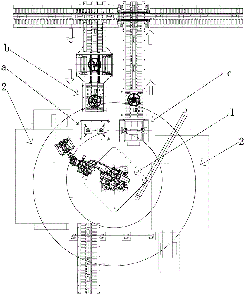
图2是本发明的设备布局图;Fig. 2 is the equipment layout diagram of the present invention;
图3是图2中的轴孔检测机构的结构示意图;Fig. 3 is the structural representation of the shaft hole detection mechanism in Fig. 2;
图4是图3中的第一检测组件和第二检测组件的结构示意图;4 is a schematic structural diagram of the first detection assembly and the second detection assembly in FIG. 3;
图5是图2中的定位读码机构的结构示意图;Fig. 5 is the structural representation of the positioning code reading mechanism in Fig. 2;
图6是图5中的三爪气缸的结构示意图;Fig. 6 is the structural representation of the three-claw cylinder in Fig. 5;
图7是图5中的第一限位杆和第二限位杆的结构示意图;FIG. 7 is a schematic structural diagram of the first limit rod and the second limit rod in FIG. 5;
图8是图2中的废屑清理机构的结构示意图。FIG. 8 is a schematic structural diagram of the waste cleaning mechanism in FIG. 2 .
具体实施方式Detailed ways
下面通过实施例,并结合附图,对本发明的技术方案作进一步具体的说明。The technical solutions of the present invention will be further described in detail below through embodiments and in conjunction with the accompanying drawings.
如图1-4所示,一种轮毂机加工自动化生产线,包括可在水平方向圆周转动的机械臂1,机械臂1的两侧均设有用于加工轮毂工件端面的车床2,机械臂1的另一侧设有轮毂端面检测设备,轮毂端面检测设备包括用于对轮毂工件的端面轴孔检测的轴孔检测机构a,轴孔检测机构a包括并列设置的第一检测组件31和第二检测组件32,第一检测组件31的圆周外侧设有多个第一支架33,第二检测组件32的圆周外侧设有多个第二支架34,第一检测组件31和第二检测组件32之间设有第三支架35,第一检测组件31和第二检测组件32结构一致,第一检测组件31和第二检测组件32均设于工作台3上,第一检测组件31包括设于工作台3上的固定架36,固定架36的底部设有第一活塞气缸37,第一活塞气缸37的输出端朝上穿过固定架36与固定筒38的底部连接,固定筒38的底部设有至少一根穿设于固定架38上的导向杆381,固定筒38的侧壁上设有通孔382,固定筒38的顶端设有检测仪383。As shown in Figure 1-4, an automatic production line for machining wheel hubs includes a robotic arm 1 that can rotate in a horizontal direction. Both sides of the robotic arm 1 are provided with
上述轮毂机加工自动化生产线包括辊道输送线、立式产品储料机、轮毂端面检测设备、机械臂等,轮毂端面检测设备包括定位读码机构、轴孔检测机构、废屑清理机构、刹车鼓检测机构;送料辊道线将轮毂送至辊道线末端,定位读码机构将轮毂进行定位,抬升至读码器识别高度,通过伺服电机进行旋转位置让读码器充分识别,判断型号后进行定位。The above wheel hub machining automation production line includes roller conveyor line, vertical product storage machine, wheel hub end face detection equipment, mechanical arm, etc. Wheel hub end face detection equipment includes positioning code reading mechanism, shaft hole detection mechanism, waste cleaning mechanism, brake drum Detection mechanism; the feeding roller table line sends the wheel hub to the end of the roller table line, the positioning code reading mechanism positions the wheel hub, lifts it to the recognition height of the code reader, and rotates the position through the servo motor to allow the code reader to fully recognize it. position.
机械臂通过夹具抓取轮毂端面放入一侧车床进行加工,加工完成后机械臂将加工好的面放入轴孔检测机构进行轴孔检测,检测合格后放入废屑清理机构进行去除加工面铝屑处理以及翻面调整;不合格的则放入不合格辊道直接输出;机械臂将废屑清理机构上翻转好的面抓取,放入另一机床中进行反面加工,加工完毕后取出放入轴孔检测机构进行检测,检测合格后放入刹车鼓检测机构,不合格则放入不合格辊道直接输出;刹车鼓检测合格后通过输出辊道线直接输送至涂装区域,不合格则通过机械臂取出放入不合格辊道线直接输出,整个生产过程带数字孪生模块,实时检测生产数据。The robotic arm grabs the end face of the hub through the fixture and puts it into one side of the lathe for processing. After the processing is completed, the robotic arm puts the machined surface into the shaft hole detection mechanism for shaft hole detection. After passing the test, it is placed into the waste cleaning mechanism to remove the machined surface. Aluminum scrap processing and turning adjustment; unqualified ones are put into the unqualified roller table for direct output; the mechanical arm grabs the turned over surface of the scrap cleaning mechanism, puts it into another machine tool for reverse processing, and takes it out after processing Put it into the shaft hole testing mechanism for testing, and put it into the brake drum testing mechanism after passing the test. If it is unqualified, put it into the unqualified roller table for direct output; after the brake drum has passed the test, it will be directly transported to the painting area through the output roller table line. Then, it is taken out and put into the unqualified roller table by the robotic arm for direct output. The entire production process is equipped with a digital twin module to detect production data in real time.
上述机械臂为工业六轴机器人,上述检测仪采用气动量仪,为现有技术,此处不再赘述,在将轮毂工件通过车床加工后,通过机械臂将轮毂工件转移至第一支架和第三支架上,第一检测组件的第一活塞气缸启动,顶动固定筒的底部,使得固定筒上移至轮毂工件的轴孔内侧,接着启动检测仪,对轮毂工件的轴孔检测,检测合格后,通过废屑清理机构清理废屑,然后将轮毂工件的另一端面加工,通过机械臂将加工后的轮毂工件转移至第二支架和第三支架上,第二检测组件的第一活塞气缸启动,顶动固定筒的底部,使得固定筒上移至轮毂工件的轴孔内侧,接着启动检测仪,对轮毂工件另一端面上的轴孔检测,检测合格后,通过机械臂将轮毂工件转移至废屑清理机构。The above-mentioned mechanical arm is an industrial six-axis robot, and the above-mentioned detector adopts a pneumatic measuring instrument, which is a prior art, and will not be repeated here. On the three brackets, the first piston cylinder of the first detection component is activated, and the bottom of the fixed cylinder is pushed up, so that the fixed cylinder is moved up to the inside of the shaft hole of the hub workpiece, and then the detector is started to detect the shaft hole of the hub workpiece, and the test is qualified After that, the waste is cleaned by the waste cleaning mechanism, and then the other end face of the hub workpiece is processed, and the processed wheel hub workpiece is transferred to the second bracket and the third bracket through the mechanical arm. The first piston cylinder of the second detection assembly Start, move the bottom of the fixed cylinder so that the fixed cylinder moves up to the inside of the shaft hole of the hub workpiece, and then start the detector to detect the shaft hole on the other end surface of the hub workpiece. to the debris removal mechanism.
如图5-6所示,轮毂端面检测设备包括定位读码机构b,定位读码机构b包括固定支架4,固定支架4的顶部设有相互平行设置的第一输送辊组41和第二输送辊组42,第一输送辊组41和第二输送辊组42之间设有可上下移动且可水平旋转的三爪气缸43,第一输送辊组41的外侧对应于三爪气缸43所在的位置处设有读码器411,三爪气缸43的底部设有可带动三爪气缸43旋转的旋转轴44,旋转轴44上设有连接板441,连接板441上对应于旋转轴44的一侧设有用于驱动旋转轴44转动的旋转电机45,旋转轴44的底部设有与固定支架4连接的底板442,旋转轴44上对应于连接板441的上方设有支撑板443,底板442和支撑板443之间设有至少一个第二活塞气缸49,支撑板443的上方设有位于旋转轴44和旋转电机45外侧的顶板444,顶板444和底板442之间设有若干导向杆445,支撑板443上设有用于供导向杆445穿过的导向套446。As shown in Figures 5-6, the wheel hub end face detection device includes a positioning code reading mechanism b, and the positioning code reading mechanism b includes a fixed
上述第一输送辊组、第二输送辊组、三爪气缸及读码器均为目前市场上已有的产品,为现有技术,此处不再赘述,在对轮毂工件定位读码前,先通过机械臂将轮毂工件转移至第一输送辊组和第二输送辊组上,轮毂工件此时位于第一限位杆和第二限位杆之间,通过第一限位杆和第二限位杆限定位置后,第二活塞气缸启动,顶动支撑板,支撑板带着旋转轴和三爪气缸上移至轮毂工件的刹车鼓处,通过三爪气缸夹紧并固定轮毂工件,然后旋转电机启动,旋转电机与旋转轴传动连接,旋转电机可驱动旋转轴转动,旋转轴通过三爪气缸带动轮毂工件转动,使得轮毂工件侧壁上的识别码被转动至读码器所在位置处,接着读码器对轮毂工件读码,读码完成后,三爪气缸取消对轮毂工件夹持,机械臂将轮毂工件转移至车床加工。The above-mentioned first conveying roller group, second conveying roller group, three-claw cylinder and code reader are all products currently on the market, which are the prior art, and will not be repeated here. First, the hub workpiece is transferred to the first conveying roller group and the second conveying roller group by the mechanical arm, and the hub workpiece is located between the first limit rod and the second limit rod at this time. After the position of the limit rod is limited, the second piston cylinder is activated, and the support plate is pushed up. The support plate moves up with the rotating shaft and the three-claw cylinder to the brake drum of the wheel hub workpiece, and the wheel hub workpiece is clamped and fixed by the three-claw cylinder, and then The rotating motor is started, and the rotating motor is connected with the rotating shaft. The rotating motor can drive the rotating shaft to rotate. The rotating shaft drives the hub workpiece to rotate through the three-claw cylinder, so that the identification code on the side wall of the hub workpiece is rotated to the position of the code reader. Then the code reader reads the code of the wheel hub workpiece. After the code reading is completed, the three-jaw cylinder cancels the clamping of the wheel hub workpiece, and the mechanical arm transfers the wheel hub workpiece to the lathe for processing.
如图5和7所示,第一输送辊组41上穿设有两个竖向设置的第一限位杆46,第二输送辊组42上穿设有两个竖向设置且可与第一限位杆46相对移动的第二限位杆47,第一限位杆46和第二限位杆47的底部分别通过第一垫板461和第二垫板471支撑,固定支架4的侧壁上设有竖板48,竖板48的内侧设有转盘481,转盘481的端面上设有长臂482,长臂482的中点处与转盘481的轴心连接,长臂482的两端分别设有可上下转动的第一连接臂483和第二连接臂484,第一连接臂483外端和第二连接臂484的外端分别与第一移动板485和第二移动板486转动连接,第一移动板485的顶端和第二移动板486的顶端分别与第一垫板461和第二垫板471连接,竖板48的内侧对应于转盘481的一侧设有至少一根横向设置的第一滑轨487,第一移动板485上和第二移动板486上分别设有与第一滑轨487配合的第一滑块488和第二滑块489,竖板48的外侧设有第三活塞气缸40,第三活塞气缸40的固定端与竖板48连接,第三活塞气缸40的输出端与第一移动板485连接。As shown in FIGS. 5 and 7 , the first conveying
将轮毂工件转移至第一输送辊组和第二输送辊组上时,第三活塞气缸启动,拉动第一移动组,使得第一移动板沿第一滑轨朝着转盘移动,第一移动板移动时,通过第一连接臂推动长臂的一端绕转盘的轴心翻转,而长臂的另一端同步反向翻转,通过第二连接臂拉动第二移动板朝着转盘同步移动,第一移动板和第二移动板从而分别通过第一垫板和第二垫板带动第一限位杆和第二限位杆同步相对移动,朝着轮毂工件移动,并推动轮毂工件移动至准确位置,以进行读码识别工序。When the hub workpiece is transferred to the first conveying roller group and the second conveying roller group, the third piston cylinder is activated to pull the first moving group, so that the first moving plate moves toward the turntable along the first sliding rail, and the first moving plate moves toward the turntable. When moving, push one end of the long arm to flip around the axis of the turntable through the first connecting arm, while the other end of the long arm flips in the opposite direction synchronously, and the second moving plate is pulled by the second connecting arm to move synchronously toward the turntable, and the first movement The plate and the second moving plate thus drive the first limit rod and the second limit rod to move synchronously and relative to each other through the first backing plate and the second backing plate respectively, move towards the hub workpiece, and push the hub workpiece to move to an accurate position, so as to Carry out the code reading and identification process.
如图8所示,轮毂端面检测设备包括废屑清理机构c,废屑清理机构c包括工作框架5和设于工作框架5底部的接屑斗51,工作框架5的顶部设有固定座52,固定座52的顶部设有平行气缸53,平行气缸53的两输出端分别设有用于夹持轮毂工件侧壁的第一夹紧组件533和第二夹紧组件534,固定座52的两侧沿平行气缸53的驱动方向分别设有第一延长臂531和第二延长臂532,第一夹紧组件533和第二夹紧组件534分别设于第一延长臂531上和第二延长臂532上,第一夹紧组件533和第二夹紧组件534之间对应于平行气缸53的上方设有吹气组件54,第一夹紧组件533和第二夹紧组件534结构一致,第一夹紧组件533包括设于平行气缸53顶部且竖向延伸的第三延长臂535和设于平行气缸53底部的第三滑块536,第一延长臂531上设有与第三滑块536配合的第二滑轨537,第三延长臂535的顶部外侧设有旋转气缸55,旋转气缸55的输出端设有位于第三延长臂535内侧的旋转块551,旋转块551的内侧设有两个可水平转动的滑轮552,吹气组件54包括设于平行气缸53上方的固定块541,固定块541上穿设有竖向设置的气管接头542,气管接头542的顶端设有可水平旋转且与气管接头542连通的旋转座543,旋转座543的侧壁上设有多个向下倾斜且朝旋转座543的外侧辐射的L型喷气管544,旋转座543的顶部设有向上喷气的喷嘴545,旋转座543的一侧设有与升降气缸546的输出端连接的横板547,升降气缸546设于工作框架5的顶面上。As shown in FIG. 8 , the wheel hub end face detection device includes a waste cleaning mechanism c, and the waste cleaning mechanism c includes a working
上述平行气缸为目前市场上已有的产品,为双活塞气缸,两端分别设有气缸杆,可同步伸缩,通过机械臂将轮毂工件转移至废屑清理机构的第一夹紧组件和第二夹紧组件之间,然后平行气缸启动,同时驱动两侧的第三延长臂沿着第二滑轨朝着平行气缸同步移动,第三延长臂上的旋转块和滑轮朝着轮毂工件的侧壁移动,直至两侧的滑轮均与轮毂工件的侧壁抵接并夹紧轮毂工件,此时升降气缸启动,控制固定块上移,使得旋转座位于轮毂工件的轴孔处,气管接头与外部送气设备连接,气管接头将气体送入旋转座,接着气体从L型喷气管喷出,对轴孔侧壁吹气除屑,同时由于气体喷出的力作用,L型喷气管会带着旋转座水平旋转,L型喷气管从而对轮毂工件的轴孔旋转式吹气除屑,此时喷嘴同步喷出气体,朝上对轮毂工件的轴孔吹气,吹气除屑更加全面,进一步提高除屑效果。The above-mentioned parallel cylinder is an existing product on the market. It is a double-piston cylinder with cylinder rods at both ends, which can be extended and retracted synchronously. The wheel hub workpiece is transferred to the first clamping component and the second Clamp between the components, and then the parallel cylinder is activated, and at the same time, the third extension arms on both sides are driven to move synchronously along the second slide rail toward the parallel cylinder, and the rotating block and pulley on the third extension arm move toward the side wall of the hub workpiece Move until the pulleys on both sides are in contact with the side wall of the hub workpiece and clamp the hub workpiece. At this time, the lifting cylinder is activated, and the fixed block is controlled to move up, so that the rotating seat is located at the shaft hole of the hub workpiece, and the air pipe joint is connected to the external air supply. When the equipment is connected, the gas pipe joint sends the gas into the rotary seat, and then the gas is sprayed from the L-shaped jet pipe, and the side wall of the shaft hole is blown to remove chips. At the same time, due to the force of the gas jet, the L-shaped jet pipe will carry the rotary seat. Horizontal rotation, the L-shaped jet pipe can blow air to the shaft hole of the hub workpiece in a rotary manner to remove chips. At this time, the nozzle synchronously sprays gas, and blows air upward to the shaft hole of the hub workpiece. crumb effect.
Claims (10)
Applications Claiming Priority (2)
| Application Number | Priority Date | Filing Date | Title |
|---|---|---|---|
| CN2022108666072 | 2022-07-22 | ||
| CN202210866607 | 2022-07-22 |
Publications (1)
| Publication Number | Publication Date |
|---|---|
| CN115178483A true CN115178483A (en) | 2022-10-14 |
Family
ID=83520583
Family Applications (1)
| Application Number | Title | Priority Date | Filing Date |
|---|---|---|---|
| CN202210931231.9A Pending CN115178483A (en) | 2022-07-22 | 2022-08-04 | Automatic production line for hub machining |
Country Status (1)
| Country | Link |
|---|---|
| CN (1) | CN115178483A (en) |
Cited By (1)
| Publication number | Priority date | Publication date | Assignee | Title |
|---|---|---|---|---|
| CN119681655A (en) * | 2025-02-21 | 2025-03-25 | 沈阳中金模具集团有限公司 | Automobile wheel hub processing device |
Citations (9)
| Publication number | Priority date | Publication date | Assignee | Title |
|---|---|---|---|---|
| CN104308187A (en) * | 2014-10-15 | 2015-01-28 | 浙江今跃机械科技开发有限公司 | Automatic hub processing equipment and method for automatically processing hub |
| CN204523671U (en) * | 2015-01-21 | 2015-08-05 | 浙江万丰科技开发有限公司 | A kind of bits of the aluminium for Motorcycle Aluminum Alloy wheel hub cleaning plant |
| US20150253222A1 (en) * | 2014-03-06 | 2015-09-10 | Richard T. Fitzpatrick, JR. | Multi-purpose gauge for hub-piloted wheel inspection |
| CN205300505U (en) * | 2016-01-11 | 2016-06-08 | 昆山德衡汉自动化设备有限公司 | Wheel hub flange hole check out test set |
| CN106249695A (en) * | 2016-09-20 | 2016-12-21 | 图灵视控(北京)科技有限公司 | Wheel hub CNC flexible manufacturing system (FMS) based on machine vision |
| CN106395328A (en) * | 2016-11-19 | 2017-02-15 | 浙江跃岭股份有限公司 | Automatic wheel hub turning and chipping removing device |
| CN209811882U (en) * | 2019-02-28 | 2019-12-20 | 浙江今跃机械科技开发有限公司 | Hub drilling detection device |
| CN111055152A (en) * | 2019-12-18 | 2020-04-24 | 苏州香农智能科技有限公司 | Hub center hole machining and measuring system |
| CN112122914A (en) * | 2020-10-20 | 2020-12-25 | 秦皇岛信能能源设备有限公司 | A kind of auxiliary assembly device and method of wheel hub decoration |
-
2022
- 2022-08-04 CN CN202210931231.9A patent/CN115178483A/en active Pending
Patent Citations (9)
| Publication number | Priority date | Publication date | Assignee | Title |
|---|---|---|---|---|
| US20150253222A1 (en) * | 2014-03-06 | 2015-09-10 | Richard T. Fitzpatrick, JR. | Multi-purpose gauge for hub-piloted wheel inspection |
| CN104308187A (en) * | 2014-10-15 | 2015-01-28 | 浙江今跃机械科技开发有限公司 | Automatic hub processing equipment and method for automatically processing hub |
| CN204523671U (en) * | 2015-01-21 | 2015-08-05 | 浙江万丰科技开发有限公司 | A kind of bits of the aluminium for Motorcycle Aluminum Alloy wheel hub cleaning plant |
| CN205300505U (en) * | 2016-01-11 | 2016-06-08 | 昆山德衡汉自动化设备有限公司 | Wheel hub flange hole check out test set |
| CN106249695A (en) * | 2016-09-20 | 2016-12-21 | 图灵视控(北京)科技有限公司 | Wheel hub CNC flexible manufacturing system (FMS) based on machine vision |
| CN106395328A (en) * | 2016-11-19 | 2017-02-15 | 浙江跃岭股份有限公司 | Automatic wheel hub turning and chipping removing device |
| CN209811882U (en) * | 2019-02-28 | 2019-12-20 | 浙江今跃机械科技开发有限公司 | Hub drilling detection device |
| CN111055152A (en) * | 2019-12-18 | 2020-04-24 | 苏州香农智能科技有限公司 | Hub center hole machining and measuring system |
| CN112122914A (en) * | 2020-10-20 | 2020-12-25 | 秦皇岛信能能源设备有限公司 | A kind of auxiliary assembly device and method of wheel hub decoration |
Cited By (2)
| Publication number | Priority date | Publication date | Assignee | Title |
|---|---|---|---|---|
| CN119681655A (en) * | 2025-02-21 | 2025-03-25 | 沈阳中金模具集团有限公司 | Automobile wheel hub processing device |
| CN119681655B (en) * | 2025-02-21 | 2025-10-17 | 沈阳中金模具集团有限公司 | Automobile hub machining device |
Similar Documents
| Publication | Publication Date | Title |
|---|---|---|
| CN109822217B (en) | An automated laser welding system | |
| CN108890127B (en) | Welding equipment for automobile safety airbag generator | |
| CN111761079A (en) | A double-spindle double-turret upside-down machine tool | |
| CN111646204B (en) | Multi-station crankshaft automatic three-dimensional measuring system | |
| CN116175202B (en) | Reducer housing assembly automatic processing and testing production line | |
| CN103962901A (en) | Fully-automatic grinder | |
| CN113720905A (en) | Brake disc eddy current testing machine | |
| CN112934740B (en) | A pipelined flange detection system and detection method thereof | |
| CN108242872B (en) | Assembly mechanism of rotor processing equipment | |
| CN111055152A (en) | Hub center hole machining and measuring system | |
| CN113369892A (en) | Automatic hard tube assembly line | |
| CN113334147A (en) | Full-automatic processing system for flywheel housing | |
| CN211740155U (en) | Automatic device and system for checking meshing of disc gears | |
| CN210304621U (en) | Bearing outer ring upper and lower face parallel difference detection device | |
| CN116922173A (en) | Dust-free full-automatic screw rod polishing equipment and working method | |
| CN120286999A (en) | A three-in-one device for post-flight inspection, dust removal and milling of power battery packs | |
| CN109436731A (en) | A kind of transmission equipment | |
| CN118682544A (en) | A transfer and transportation device for motor shaft processing | |
| CN217451067U (en) | Polishing outer welding seam detector | |
| CN217451045U (en) | Full-automatic part quality inspection sorting equipment | |
| CN110977494B (en) | RC intelligent manufacturing production line for optical communication precision parts | |
| CN111673478B (en) | A rotor processing spot welding test integrated machine | |
| CN211992013U (en) | Hub center hole machining and measuring system | |
| CN219212444U (en) | Automatic production line for numerical control turning and finished product detection of shaft parts | |
| CN120715692B (en) | An automated production line for machining long shaft-type workpieces and its machining process |
Legal Events
| Date | Code | Title | Description |
|---|---|---|---|
| PB01 | Publication | ||
| PB01 | Publication | ||
| SE01 | Entry into force of request for substantive examination | ||
| SE01 | Entry into force of request for substantive examination | ||
| RJ01 | Rejection of invention patent application after publication |
Application publication date: 20221014 |
|
| RJ01 | Rejection of invention patent application after publication |