CN115163940A - Multifunctional protective assembly for chemical pipeline connecting pipe - Google Patents
Multifunctional protective assembly for chemical pipeline connecting pipe Download PDFInfo
- Publication number
- CN115163940A CN115163940A CN202210419789.9A CN202210419789A CN115163940A CN 115163940 A CN115163940 A CN 115163940A CN 202210419789 A CN202210419789 A CN 202210419789A CN 115163940 A CN115163940 A CN 115163940A
- Authority
- CN
- China
- Prior art keywords
- pipeline
- grooves
- sealing
- shell
- movable
- Prior art date
- Legal status (The legal status is an assumption and is not a legal conclusion. Google has not performed a legal analysis and makes no representation as to the accuracy of the status listed.)
- Granted
Links
- 239000000126 substance Substances 0.000 title claims abstract description 20
- 230000001681 protective effect Effects 0.000 title claims abstract description 7
- 238000007789 sealing Methods 0.000 claims abstract description 108
- 238000009826 distribution Methods 0.000 claims description 2
- 238000012544 monitoring process Methods 0.000 claims description 2
- 210000001503 joint Anatomy 0.000 description 9
- 238000003780 insertion Methods 0.000 description 7
- 230000037431 insertion Effects 0.000 description 7
- 238000009434 installation Methods 0.000 description 5
- 238000004519 manufacturing process Methods 0.000 description 5
- 238000012824 chemical production Methods 0.000 description 3
- 238000013459 approach Methods 0.000 description 1
- 230000009286 beneficial effect Effects 0.000 description 1
- 230000005540 biological transmission Effects 0.000 description 1
- 238000010586 diagram Methods 0.000 description 1
- 230000000694 effects Effects 0.000 description 1
- 230000006872 improvement Effects 0.000 description 1
- 238000007689 inspection Methods 0.000 description 1
- 230000007246 mechanism Effects 0.000 description 1
- 238000000034 method Methods 0.000 description 1
- 238000013508 migration Methods 0.000 description 1
- 230000005012 migration Effects 0.000 description 1
- 238000012986 modification Methods 0.000 description 1
- 230000004048 modification Effects 0.000 description 1
- 230000000737 periodic effect Effects 0.000 description 1
- 231100000614 poison Toxicity 0.000 description 1
- 230000007096 poisonous effect Effects 0.000 description 1
- 230000008569 process Effects 0.000 description 1
- 238000012545 processing Methods 0.000 description 1
- 230000008439 repair process Effects 0.000 description 1
Images




Classifications
-
- F—MECHANICAL ENGINEERING; LIGHTING; HEATING; WEAPONS; BLASTING
- F16—ENGINEERING ELEMENTS AND UNITS; GENERAL MEASURES FOR PRODUCING AND MAINTAINING EFFECTIVE FUNCTIONING OF MACHINES OR INSTALLATIONS; THERMAL INSULATION IN GENERAL
- F16L—PIPES; JOINTS OR FITTINGS FOR PIPES; SUPPORTS FOR PIPES, CABLES OR PROTECTIVE TUBING; MEANS FOR THERMAL INSULATION IN GENERAL
- F16L21/00—Joints with sleeve or socket
- F16L21/06—Joints with sleeve or socket with a divided sleeve or ring clamping around the pipe ends
-
- F—MECHANICAL ENGINEERING; LIGHTING; HEATING; WEAPONS; BLASTING
- F16—ENGINEERING ELEMENTS AND UNITS; GENERAL MEASURES FOR PRODUCING AND MAINTAINING EFFECTIVE FUNCTIONING OF MACHINES OR INSTALLATIONS; THERMAL INSULATION IN GENERAL
- F16L—PIPES; JOINTS OR FITTINGS FOR PIPES; SUPPORTS FOR PIPES, CABLES OR PROTECTIVE TUBING; MEANS FOR THERMAL INSULATION IN GENERAL
- F16L17/00—Joints with packing adapted to sealing by fluid pressure
- F16L17/02—Joints with packing adapted to sealing by fluid pressure with sealing rings arranged between outer surface of pipe and inner surface of sleeve or socket
-
- F—MECHANICAL ENGINEERING; LIGHTING; HEATING; WEAPONS; BLASTING
- F16—ENGINEERING ELEMENTS AND UNITS; GENERAL MEASURES FOR PRODUCING AND MAINTAINING EFFECTIVE FUNCTIONING OF MACHINES OR INSTALLATIONS; THERMAL INSULATION IN GENERAL
- F16L—PIPES; JOINTS OR FITTINGS FOR PIPES; SUPPORTS FOR PIPES, CABLES OR PROTECTIVE TUBING; MEANS FOR THERMAL INSULATION IN GENERAL
- F16L21/00—Joints with sleeve or socket
- F16L21/02—Joints with sleeve or socket with elastic sealing rings between pipe and sleeve or between pipe and socket, e.g. with rolling or other prefabricated profiled rings
- F16L21/04—Joints with sleeve or socket with elastic sealing rings between pipe and sleeve or between pipe and socket, e.g. with rolling or other prefabricated profiled rings in which sealing rings are compressed by axially-movable members
-
- F—MECHANICAL ENGINEERING; LIGHTING; HEATING; WEAPONS; BLASTING
- F17—STORING OR DISTRIBUTING GASES OR LIQUIDS
- F17D—PIPE-LINE SYSTEMS; PIPE-LINES
- F17D5/00—Protection or supervision of installations
- F17D5/005—Protection or supervision of installations of gas pipelines, e.g. alarm
-
- F—MECHANICAL ENGINEERING; LIGHTING; HEATING; WEAPONS; BLASTING
- F17—STORING OR DISTRIBUTING GASES OR LIQUIDS
- F17D—PIPE-LINE SYSTEMS; PIPE-LINES
- F17D5/00—Protection or supervision of installations
- F17D5/02—Preventing, monitoring, or locating loss
- F17D5/06—Preventing, monitoring, or locating loss using electric or acoustic means
Landscapes
- Engineering & Computer Science (AREA)
- General Engineering & Computer Science (AREA)
- Mechanical Engineering (AREA)
- Physics & Mathematics (AREA)
- Fluid Mechanics (AREA)
- Acoustics & Sound (AREA)
- Quick-Acting Or Multi-Walled Pipe Joints (AREA)
Abstract
The invention relates to the field of pipeline connecting fittings, in particular to a multifunctional protective assembly for a chemical pipeline connecting pipe; the sealing device comprises a rectangular shell and two pipelines to be connected, wherein a transverse cylindrical block coaxial with the shell is arranged in the shell, a channel coaxial with the cylindrical block is formed in the cylindrical block, the shell is connected with the cylindrical block through a connecting support component to enable the cylindrical block to keep stable, annular first grooves coaxial with the channel are formed in two ends of the cylindrical block, first piston rings in sealing contact fit with the first grooves are arranged in the first grooves, first movable pipes coaxial with the first piston rings are arranged on the outer sides of the first piston rings, fourth conical surfaces are formed in the outer ends of the first movable pipes, and first sealing strips are embedded in the fourth conical surfaces; according to the invention, the air pump is used for controlling the horizontal movement of the first movable pipe, so that the first movable end is in sealing contact fit with the pipeline, the connection part of the first movable pipe and the pipeline is in a conical surface structure, the connection contact area is increased, and the sealing performance of the connection part of the pipeline is ensured.
Description
Technical Field
The invention relates to the technical field of chemical equipment, in particular to a multifunctional protective assembly for a chemical pipeline connecting pipe.
Background
Chemical pipeline plays the key role in different production process equipment connect and material transport in large-scale chemical production, chemical pipeline carries in chemical production mostly is poisonous simultaneously, it is harmful, the material that has corrosivity, because the actual production needs, chemical pipeline in chemical production mostly adopts the mode that the multistage is connected to carry out the material transport, but along with the increase of chemical pipeline live time, and the corruption of material, material leakage phenomenon appears easily in chemical pipeline's junction, and the leakage of material leads to the fact the incident easily, but leak and handle the transport that most need will stop the material to the pipe connection among the prior art, and need handle just can repair the material in the pipeline, and the operation is inconvenient, and influence production, and the production cost is improved.
Disclosure of Invention
In order to solve the problem of inconvenience in repairing chemical pipeline joints in the prior art, the invention provides a multifunctional protective component for chemical pipeline connecting pipes.
The technical scheme of the invention is as follows:
the invention provides a protective component for a multifunctional chemical pipeline connecting pipe, which comprises a rectangular shell and two pipelines to be connected, wherein the shell comprises an upper sealing cover and a lower sealing cover, the upper sealing cover and the lower sealing cover are connected in a sealing manner through a connecting and fixing component, connecting ends of the pipelines are respectively fixed in the shell, a transverse cylindrical block coaxial with the shell is arranged in the shell, a channel coaxial with the cylindrical block is formed in the cylindrical block, a third conical surface is formed on the inner side of the outer end of the channel, second conical surfaces are formed on the outer sides of the connecting ends of the pipelines, a first conical surface is formed on the inner side of the connecting end of the pipeline, the shell is connected with a connecting block of a supporting component to enable the cylindrical block to keep stable, annular first grooves coaxial with the channel are formed at two ends of the cylindrical block, first piston rings in sealing contact fit with the first grooves are arranged in the first grooves, first movable pipes coaxial with the first piston rings are arranged on the outer sides of the first piston rings, fourth conical surfaces are respectively provided with a fourth conical surface, first sealing strip is arranged on the outer end of the first movable pipe, a driving device for driving the cylindrical block to be in a horizontal direction, and the first sealing strip is arranged between the first sealing strip and a device capable of driving the first sealing strip to be in a horizontal direction, and a distance capable of driving device capable of driving the first sealing strip to be larger than a pipeline.
Further, annular second grooves are formed in two ends of the cylindrical block, the outer end of each second groove is flush with a third conical surface of the corresponding side, the second grooves are located on the inner side of the corresponding first groove and coaxial with the first groove, second piston rings matched with the second grooves in a sealing contact mode are arranged in the second grooves, second movable pipes coaxial with the second piston rings are fixedly arranged on the outer sides of the second piston rings, fifth conical surfaces are arranged on the outer sides of the outer ends of the second movable pipes, annular second sealing strips are embedded in the fifth conical surfaces, the fifth conical surfaces can be matched with the first conical surfaces of the corresponding side pipelines in a sealing contact mode, the driving device is communicated with the second grooves of the corresponding sides through a connection control structure, the driving device pushes the second movable pipes to move horizontally, the length of the second movable pipes is larger than the distance from the pipeline to the cylindrical block, a plurality of fan-shaped baffles uniformly distributed in an annular mode are hinged to the outer sides of the second grooves, torsional springs are installed at hinged positions of the fan-shaped baffles, adjacent fan-shaped baffles are matched in a sealing contact mode, and all the fan-shaped baffles located on the outer sides of the same second groove can completely seal and shield the corresponding second grooves.
Further, the pipeline link outside all is equipped with two semi-annular clamp spare that are upper and lower symmetric distribution, it forms a complete clamp to be located through the fastening assembly is fixed between two clamp spare of same pipeline periphery, the clamp spare is close to the equal fixed mounting semi-annular sealing washer in columnar block one side, sealing washer concave surface one side all cooperates with the pipeline periphery sealing contact who corresponds, the sealing washer outside all is equipped with a set of jack, every jack of group all includes the jack of several along its length direction equipartition, and two sets of jacks that two sealing washers in the same pipeline outside correspond are located the front and back both sides of columnar block respectively, first movable tube outside fixed mounting two sets of inserted bars with the jack one-to-one, the inserted bar can with the slot grafting cooperation that corresponds, and first movable tube outer terminal surface cooperates with sealing washer sealing contact, be located between two clamp spares on upper portion and lie in the lower part between two clamp spares all be equipped with the horizontally lead screw, the lead screw passes through between install in the columnar block corresponds the side, correspond lead screw tip one side all fixed mounting internal thread pipe, lead screw tip one side all corresponds the meshing cooperation with the first movable tube of internal thread, the fixed gear that corresponds with the first movable tube, the external side of the reverse rotation of the lead screw, the fixed gear that corresponds respectively, the external side of the first movable tube corresponds, the first movable gear that corresponds, the internal thread corresponds.
Furthermore, the driving device comprises two vertical blind holes formed in the top of the cylindrical block, a gas supply pipeline is arranged in each blind hole and connected with a gas pump, horizontal first through holes are formed in the inner end faces of the first grooves and communicated with the interiors of the blind holes, first check valves communicated with the first through holes are fixedly mounted at one ends of the first through holes close to the blind holes, and the first check valves are connected with the gas supply pipeline.
Furthermore, the gas monitoring and alarming device comprises a gas detector arranged in the shell, the gas detector monitors gas in the shell in real time, an alarm is arranged outside the shell, and when the gas leaks, the alarm gives an early warning.
Furthermore, the supporting and connecting assembly comprises a plurality of vertical connecting rods fixedly installed on the inner bottom surface of the lower sealing cover, the connecting rods can be detached from the corresponding sides of the connecting column-shaped blocks, vertical mounting holes are formed in the top of the upper sealing cover, a first baffle capable of sealing and plugging the upper sealing cover is arranged in each mounting hole, a plurality of vertical fixing rods are fixedly installed at the bottom of each first baffle, and the connecting column-shaped blocks can be detached from the corresponding sides of the fixing rods.
The invention achieves the following beneficial effects:
according to the invention, the horizontal movement of the first movable pipe is controlled in a mode that the air pump is communicated with the first groove, and the first movable pipe is always pushed by the air pump, so that the first movable end is in sealing contact fit with the pipeline connecting end on the corresponding side; meanwhile, the second movable pipe is arranged as a standby sealing connecting piece, when gas leakage or other emergency situations occur, the second movable pipe can be used for standby, an automatic emergency processing mechanism is added, large-scale leakage can be effectively avoided in real time, safety accidents are avoided, when the first sealing strip is replaced regularly, the first sealing strip can be replaced only by sealing and butting the second movable pipe and the pipeline without stopping the transmission of gas in the pipeline, and the daily production cannot be influenced; the invention adopts a mode of matching the semi-annular sealing ring with the first movable pipe, so that the outer end of the first movable pipe is in sealing connection with the sealing gasket, and meanwhile, the connection part of the two sealing gaskets on the periphery of the same pipeline is pulled and extruded through the insertion matching of the insertion rod and the insertion hole, so that the connection is tighter, thereby realizing the sealing contact matching of the fourth conical surface and the first conical surface, simultaneously, the outer end of the first movable pipe is in sealing contact matching with the sealing ring, and the two surfaces at the same connection part are in sealing contact matching, thereby greatly improving the sealing effect.
Drawings
Fig. 1 is a schematic view of the overall structure of the present invention.
Fig. 2 is a schematic view of the internal structure of embodiment 1.
Fig. 3 is an enlarged view of a portion i in fig. 2.
FIG. 4 is a schematic view of the internal structure of embodiment 2
Fig. 5 is an enlarged view of a portion ii of fig. 4.
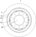
Fig. 6 is an enlarged view of the view from the direction a in fig. 4.
FIG. 7 is a schematic view of the internal structure of embodiment 3
Fig. 8 is an enlarged view of a portion iii of fig. 7.
FIG. 9 is a state diagram of use of embodiment 3.
Fig. 10 is an enlarged view of a portion iv of fig. 9.
Fig. 11 is an enlarged view of the view from direction B in fig. 9.
Detailed Description
To facilitate an understanding of the present invention by those skilled in the art, specific embodiments thereof are described below with reference to the accompanying drawings.
The technical solutions in the embodiments of the present invention will be clearly and completely described below with reference to the drawings in the embodiments of the present invention, and it is obvious that the described embodiments are only a part of the embodiments of the present invention, and not all of the embodiments. All other embodiments, which can be derived by a person skilled in the art from the embodiments given herein without making any creative effort, shall fall within the protection scope of the present invention.
In the description of the present application, it should be noted that the terms "center", "upper", "lower", "left", "right", "vertical", "horizontal", "inner", "outer", etc. indicate orientations or positional relationships based on the orientations or positional relationships shown in the drawings, and are only for convenience of description and simplicity of description, but do not indicate or imply that the device or element referred to must have a particular orientation, be constructed in a particular orientation, and be operated, and thus, should not be construed as limiting the present invention. Furthermore, the terms "first," "second," and "third" are used for descriptive purposes only and are not to be construed as indicating or implying relative importance.
It will be understood that when an element is referred to as being "mounted on" another element, it can be directly on the other element or intervening elements may also be present. When a component is referred to as being "disposed on" another component, it can be directly on the other component or intervening components may also be present. When an element is referred to as being "secured to" another element, it can be directly secured to the other element or intervening elements may also be present.
Unless defined otherwise, all technical and scientific terms used herein have the same meaning as commonly understood by one of ordinary skill in the art to which this invention belongs. The terminology used in the description of the invention herein is for the purpose of describing particular embodiments only and is not intended to be limiting of the invention. As used herein, the term "or/and" includes any and all combinations of one or more of the associated listed items.
Example 1
As shown in fig. 1, the invention provides a multifunctional protection component for a chemical pipeline adapter, which comprises a rectangular shell 1 and two pipelines 4 to be connected, wherein connecting ends of the two pipelines 4 penetrate through the shell 1 and extend into the shell 1, the connecting parts of the pipelines 4 and the shell 1 are in sealing contact fit, the shell 1 comprises an upper sealing cover 2 and a lower sealing cover 3, the upper sealing cover 2 and the lower sealing cover 3 are fixedly connected through an ear plate and a bolt, the connecting ends 4 of the two pipelines 4 are fixed in the shell 1 while the upper sealing cover 2 and the lower sealing cover 3 are fixed with each other, and sealing gaskets are arranged at the connecting parts of the upper sealing cover 2 and the lower sealing cover 3, so that the sealing performance of the shell 1 in use is ensured.
Be equipped with horizontal cylindricality piece 6 in the shell 1, as shown in fig. 2, several vertical connecting rods 7 of bottom surface fixed mounting in the sealed lid 3 down, connecting rod 7 can be dismantled the spliced pole piece 6 and correspond the side, connecting rod 7 cooperates for pegging graft with a connected mode of cylindricality piece 6, go up sealed lid 2 top surfaces and offer mounting hole 8, demountable installation has the baffle 9 that can seal its shutoff in the mounting hole 8, as shown in fig. 3, can maintain and periodic inspection through mounting hole 8 to shell 1 inside like this.
A plurality of vertical dead levers 10 of baffle 9 bottom surface fixed mounting, dead lever 10 can dismantle the connection cylindricality piece 6 and correspond the side, and dead lever 10 cooperates for pegging graft with a connected mode of cylindricality piece 6, is fixed in shell 1 with cylindricality piece 6 simultaneously through dead lever 10 and connecting rod 7 like this in, can make cylindricality piece 6 more stable when using.
Set up horizontally passageway 40 in the cylindricality piece 6, the third conical surface is all seted up in the passageway 40 both ends outside, first conical surface is all seted up to pipeline 4's link inboard, second conical surface is all seted up in pipeline 4's the link outside, the annular first recess 11 coaxial with passageway 40 is all seted up to the both ends face of cylindricality piece 6, all be equipped with the first piston ring 12 of sealing contact complex with it in the first recess 11, the first movable tube 13 of the equal fixed mounting in outside of first piston ring 12, the length of first movable tube 13 is greater than the pipeline 4 link and corresponds the distance between the end with cylindricality piece 6, fourth conical surface is all seted up to first movable tube 13 outer end inboard, fourth conical surface can cooperate with the second conical surface sealing contact that corresponds the side pipeline, fourth conical surface all inlays and is equipped with first sealing strip 14 simultaneously, and first sealing strip 14 connects into complete annular at fourth conical surface, like this in the use, through fourth conical surface and the second conical surface sealing contact cooperation that corresponds the side pipeline, thereby make two pipelines 4 carry out sealing connection through passageway 40.
Two vertical blind holes 15 are all opened on the top surface of cylindrical block 6, blind holes 15 correspond to first grooves 11 one-to-one, communicating horizontal through holes 16 inside blind holes 15 corresponding to side are all opened at the inner end of first groove 11, the equal fixed mounting of one end outside that horizontal through holes 16 are close to blind holes 15 is with communicating first solenoid valve 17 therewith, all be equipped with air supply pipeline 18 in blind holes 15, first solenoid valve 17 communicates with air supply pipeline 18 corresponding to side respectively, equal fixed mounting air pump 19 in the blind holes 15 upper end outside, air pump 19 all is connected with air supply pipeline 18 corresponding to side, like this air pump 19 can supply air to first groove 11 corresponding to side through air supply pipeline 18 and first solenoid valve 17, thereby make first piston ring 12 can follow corresponding first groove 11 horizontal migration, promote first movable tube 13 corresponding to side to be close to pipeline 4 corresponding to side, make first movable tube 13 and corresponding side pipeline 4's sealed butt joint, shell 1 outside is equipped with the controller, 19, first solenoid valve 17 all is connected with the power, first solenoid valve 19, first piston ring 17 all is connected with the controller, first movable tube 13 is connected to the pipeline 4 of corresponding to corresponding side through air pump, thereby the sealed installation hole of air pump is controlled to first groove 11 simultaneously, thereby the sealed movable tube 14 is carried out to the sealed installation of air pump 12, thereby the inside can be controlled the sealed movable tube 14 through the corresponding to the first groove of air pump 12.
Install gas detector 37 in the shell 1, the shell 1 outside is equipped with alarm 38, and alarm 38, gas detector 37 all are connected with the power, and alarm 38, gas detector 37 all are connected with the controller, can the inside gas leakage that takes place of real-time supervision shell 1 through gas detector 37, and when gas leakage takes place, gas detector 37 feeds back information to the controller, and the controller makes alarm 38 send out the police dispatch newspaper.
Example 2
Different from the embodiment 1, the third conical surfaces are respectively provided with an annular second groove 20 concentric with the first groove 11, the second grooves 20 are respectively located at the inner sides of the corresponding first grooves 11, a second piston ring 21 in sealing contact fit with the second grooves 20 is also arranged in the second grooves 20, the outer ends of the second piston rings 21 are respectively fixedly provided with a second movable tube 22, the inner sides of the outer ends of the second movable tubes 22 are respectively provided with a fifth conical surface, the fifth conical surfaces are parallel to the third conical surfaces, the outer sides of the outer ends of the second movable tubes 22 are respectively provided with a sixth conical surface, the sixth conical surfaces are respectively embedded with a second sealing strip 23, the second sealing strips 23 are annularly embedded on the sixth conical surfaces, as shown in fig. 5, the sixth conical surfaces can be in sealing butt joint with the first conical surfaces of the corresponding side pipelines 4, meanwhile, the inner end surfaces of the second grooves 20 are respectively provided with a second through hole 24 communicated with the blind hole 15 at the corresponding side, the outer side of the second through hole 24 is respectively fixedly provided with a second electromagnetic valve 25 at the outer side close to one end of the second through hole 15, the second through hole 25 is respectively connected with the power supply and the electromagnetic valve 18, the second electromagnetic valve 25 is also communicated with the corresponding side pipeline 18; the second groove 20 is thus communicated with the air pump 19 of the corresponding side through the corresponding second solenoid valve 25, and the second piston ring 21 is horizontally moved along the corresponding second groove 20 by air supply and suction of the air pump 19.
A plurality of sector baffles 26 which are uniformly distributed in an annular shape are hinged on the outer side of each second groove 20, torsion springs are arranged at the hinged installation positions of the sector baffles 26, all the sector baffles 26 positioned on the outer side of the same second groove 20 are spliced to form a complete ring, and all the sector baffles 26 positioned on the outer side of the same second groove 20 are used for sealing and shielding the second groove 20; as shown in fig. 6, in a general use state, that is, when the first movable pipe 13 is normally in sealed butt joint with the pipeline 4, the second movable pipe 22 serves as a standby sealed butt joint structure, and all the sector baffles 26 seal and block the second grooves 20 on the corresponding sides; when the first movable pipe 13 and the pipeline 4 butt joint part leak, the second electromagnetic valve 25 is opened, so that the air pump 19 supplies air to the inside of the second groove 20, so that the second piston ring 21 moves towards the outside along the second groove 20, so that the sixth conical surface at the outside of the second movable pipe 22 is in sealing contact with the second conical surface of the corresponding side pipeline 4, and the second piston ring is sealed through the sealing ring 23, so that the second movable pipe 22 is in sealing butt joint with the pipeline 4 of the corresponding side, the leakage can be effectively avoided, corresponding emergency measures can be taken according to the leakage, and the first sealing strip 14 is replaced.
Meanwhile, a vertical air outlet hole 27 can be formed in the bottom of the lower sealing cover 3, an air outlet valve 28 is installed at the lower end of the air outlet hole 27 through a connecting pipe, as shown in fig. 4, when a medium conveyed in the pipeline 4 needs to be monitored regularly, the medium is firstly withdrawn through the first movable pipe 13, the second movable pipe 22 extends out to be in sealed butt joint with the pipeline 4, then the second movable pipe 22 is withdrawn, the first movable pipe 13 extends out to be in sealed butt joint with the pipeline 4, part of the gas medium moves to the inside of the shell 1 in two times of alternation, the fan-shaped baffle 26 seals and shields the second groove 20, at the moment, the gas medium in the shell 1 is discharged by opening the air outlet valve 28, and therefore the gas medium conveyed in the inside of the pipeline 4 can be monitored regularly.
Example 3
Different from embodiment 1, as shown in fig. 7, the periphery of the connecting end of the pipeline 4 is provided with two semicircular hoop members 5 which are distributed up and down, a complete hoop is formed between the two hoop members 5 which are positioned on the periphery of the same pipeline 4 through the fixing of a fastening assembly, so that the end of the pipeline 4 corresponding to the connecting end is fixed, the hoop members 5 are close to one side of the cylindrical block 6 and are fixedly provided with semicircular sealing rings 29, the concave side of each sealing ring 29 is in sealing contact and fit with the periphery of the pipeline 4, horizontal lead screws 30 are arranged between the two hoop members 5 positioned on the upper part of the cylindrical block 6 and between the two hoop members 5 positioned on the lower part, the upper part of each hoop member 5 is close to one side of the middle part of the shell 1 and is fixedly provided with an internal threaded pipe 31, two ends of each lead screw 30 extend into and are in threaded connection with the internal threaded pipes 31 corresponding to the corresponding side, the internal threaded pipes 31 corresponding to the two ends of the lead screws 30 are opposite in screwing directions, meanwhile, the top and the bottom of the cylindrical block 6 are respectively provided with power devices which can drive the corresponding lead screws 30 to rotate forward and backward, and the lead screws 30 can be driven by the internal threaded pipes 31 or the lead screws 30, and the two ends of the lead screws can be driven by the internal pipes 30, and the lead screws 30 can be driven by the power devices which are simultaneously, and the lead screws which are close to the middle parts of the lead screws 30.
The working principle is as follows: at the beginning of installation, as shown in fig. 8, the first movable tubes 8 are located outside the corresponding seal rings 29, and the first gear 32 is not engaged with the second gear 32 on the corresponding side, then both first movable tubes 13 are moved to the outside by the air pump 19, so that the insertion rods 34 are moved to one side of the seal rings 29, and the power device drives the corresponding lead screw 30 to rotate, so that the internally threaded tubes 31 on both ends of the lead screw 30 are moved to one side of the middle of the lead screw 30, so that the second gear 33 gradually approaches the first gear 32, and when the front end portions of all the insertion rods 34 are inserted into the corresponding insertion holes 35, and at this time, the fourth tapered surface and the fourth tapered surface are not in contact engagement, at this time, the first gear 32 is engaged with the second gear 33, the power device continues to drive the lead screw 30 to rotate, the first gear 32 drives the second gear 33 on the corresponding side to rotate, so that the insertion rods 34 drive the corresponding seal rings 29 to rotate, because the diameter of the first gear 32 is much smaller than the diameter of the second gear 33, so that the seal rings 29 are located on the outer periphery of the corresponding second tapered surface, and the corresponding seal rings 29 are not pressed against the corresponding pull pipe 13, and the pull ring 13, so that the pull ring 29 is pressed by the pull ring 13, and the pull ring 13 is not pressed by the pull ring 13, and the pull ring is pressed by the pull ring 13, the joint of the two sealing rings 29 is further sealed in the process that the sealing rings 29 rotate along with the insert rod 34; at this time, the fourth conical surface and the second conical surface are in sealing contact fit between the pipeline 4 and the cylindrical block 6, as shown in fig. 10, meanwhile, the sealing ring 29 is in sealing contact fit with the outer side of the first movable pipe 13, the two surfaces are in sealing contact fit, and locking is performed through engagement of the first gear 32 and the second gear 33, so that the joint of the two sealing rings 29 is extruded, and the pipeline 4 is stronger in connection sealing performance of the cylindrical block 6.
The above-described embodiments of the present invention do not limit the scope of the present invention. Any modification, equivalent replacement, and improvement made within the spirit and principle of the present invention should be included in the scope of the claims of the present invention.
Claims (6)
1. The utility model provides a multi-functional chemical pipeline is taken over and is used protective assembly which characterized in that: the pipeline leakage alarm device comprises a rectangular shell and two pipelines which need to be connected, the shell comprises an upper sealing cover and a lower sealing cover, the upper sealing cover and the lower sealing cover are connected in a sealing mode through a connecting and fixing component and respectively fix connecting ends of the pipelines in the shell, a transverse cylindrical block coaxial with the shell is arranged in the shell, a channel coaxial with the shell is formed in the cylindrical block, a third conical surface is formed in the inner side of the outer end of the channel, a second conical surface is formed in the outer side of the connecting end of the pipeline, a first conical surface is formed in the inner side of the connecting end of the pipeline, the shell enables the cylindrical block to keep stable through a connecting and supporting component connecting column, annular first grooves coaxial with the channel are formed in the two ends of the cylindrical block, first piston rings in sealing contact fit with the first grooves are arranged in the first grooves, first movable pipes coaxial with the outer sides of the first piston rings are installed on the outer sides of the first piston rings, fourth conical surfaces are provided with fourth conical surfaces, first sealing strips are embedded with the fourth conical surfaces, the first sealing strips are annular, the fourth conical surfaces can be respectively in sealing contact fit with the second conical surfaces of the corresponding sides, the cylindrical blocks, driving devices are provided with driving devices respectively connected with the two first piston rings, the outer ends of the first movable pipes, the pipeline leakage alarm device, and the length of the first movable grooves is greater than that the outer distance of the first pipeline leakage alarm device.
2. The multifunctional chemical pipeline connecting pipe protection assembly as claimed in claim 1, wherein the protection assembly comprises: the cylindrical block is provided with two annular second grooves at two ends, the outer ends of the second grooves are flush with third conical surfaces of corresponding sides, the second grooves are located on the inner sides of the first grooves and coaxial with the first grooves, second piston rings matched with the second grooves in a sealing contact mode are arranged in the second grooves, second movable pipes coaxial with the second grooves are fixedly arranged on the outer sides of the second piston rings, fifth conical surfaces are arranged on the outer sides of the outer ends of the second movable pipes, annular second sealing strips are embedded in the fifth conical surfaces, the fifth conical surfaces can be matched with the first conical surfaces of pipelines on the corresponding sides in a sealing contact mode, the driving device is communicated with the second grooves of the corresponding sides through a connection control structure, the driving device pushes the second movable pipes to move horizontally, the length of the second movable pipes is larger than the distance from the pipeline to the cylindrical block, a plurality of fan-shaped baffles uniformly distributed in an annular mode are hinged to the outer sides of the second grooves, torsional springs are arranged at the hinged positions of the fan-shaped baffles, the adjacent fan-shaped baffles are matched in a sealing contact mode, and all the fan-shaped baffles located on the outer sides of the same second grooves can completely seal the corresponding second grooves.
3. The multifunctional chemical pipeline connecting pipe protection assembly as claimed in claim 1, wherein the protection assembly comprises: the pipeline link outside all be equipped with two semi-annular clamp spare that are upper and lower symmetric distribution, it forms a complete clamp to be located between two clamp spare of same pipeline periphery through the fastening component is fixed, the clamp spare is close to the equal fixed mounting semi-annular sealing washer in cylindrical block one side, sealing washer concave surface one side all cooperates with the pipeline periphery sealing contact who corresponds, the sealing washer outside all is equipped with a set of jack, every jack of group all includes the jack of several along its length direction equipartition, and two sets of jacks that two sealing washers in the same pipeline outside correspond are located the front and back both sides of cylindrical block respectively, first movable tube outside fixed mounting two sets of inserted bars with the jack one-to-one, the inserted bar can with the slot grafting cooperation that corresponds, and first movable tube outer terminal surface cooperates with sealing washer sealing contact, be located between two clamp spares on upper portion and lie in the lower part between two clamp spares all be equipped with the horizontally lead screw, the lead screw passes through between install in the corresponding side of cylindrical block, correspond lead screw tip one side all fixed mounting internal thread pipe, lead screw tip one side all corresponds the meshing cooperation with the internal thread of first movable tube, the internal thread side of the fixed gear that corresponds respectively, the reverse suit, the external side of lead screw corresponds the first movable gear and the external gear that the first movable gear is close to the first fixed gear that the first fixed gear is close to, the first fixed gear that the external side, the internal thread is close to the first fixed gear that the internal thread is close to the first movable gear.
4. The multifunctional chemical pipeline connecting pipe protection assembly as claimed in claim 1, 2 or 3, wherein: the driving device comprises two vertical blind holes formed in the top of the cylindrical block, an air supply pipeline is arranged in each blind hole and connected with an air pump, horizontal first through holes are formed in the inner end faces of the first grooves and communicated with the interiors of the blind holes, first check valves communicated with the first through holes are fixedly installed at one ends of the first through holes close to the blind holes, and the first check valves are connected with the air supply pipeline.
5. The multifunctional chemical pipeline connecting pipe protection assembly as claimed in claim 1, 2 or 3, wherein: the gas monitoring and alarming device comprises a gas detector arranged in the shell, the gas detector monitors gas in the shell in real time, an alarm is arranged outside the shell, and when the gas leaks, the alarm gives out early warning.
6. The multifunctional chemical pipeline connecting pipe protection assembly as claimed in claim 1, 2 or 3, wherein: the supporting and connecting assembly comprises a plurality of vertical connecting rods fixedly arranged on the inner bottom surface of the lower sealing cover, the connecting rods can be detached to connect the connecting column-shaped blocks to correspond to the sides, vertical mounting holes are formed in the top of the upper sealing cover, a first baffle capable of sealing and plugging the upper sealing cover is arranged in the mounting holes, a plurality of vertical fixing rods are fixedly arranged at the bottom of the first baffle, and the connecting column-shaped blocks can be detached to correspond to the sides.
Priority Applications (1)
| Application Number | Priority Date | Filing Date | Title |
|---|---|---|---|
| CN202210419789.9A CN115163940B (en) | 2022-04-21 | 2022-04-21 | Multifunctional protection assembly for chemical pipeline joint pipe |
Applications Claiming Priority (1)
| Application Number | Priority Date | Filing Date | Title |
|---|---|---|---|
| CN202210419789.9A CN115163940B (en) | 2022-04-21 | 2022-04-21 | Multifunctional protection assembly for chemical pipeline joint pipe |
Publications (2)
| Publication Number | Publication Date |
|---|---|
| CN115163940A true CN115163940A (en) | 2022-10-11 |
| CN115163940B CN115163940B (en) | 2024-02-06 |
Family
ID=83483299
Family Applications (1)
| Application Number | Title | Priority Date | Filing Date |
|---|---|---|---|
| CN202210419789.9A Active CN115163940B (en) | 2022-04-21 | 2022-04-21 | Multifunctional protection assembly for chemical pipeline joint pipe |
Country Status (1)
| Country | Link |
|---|---|
| CN (1) | CN115163940B (en) |
Cited By (2)
| Publication number | Priority date | Publication date | Assignee | Title |
|---|---|---|---|---|
| CN116734053A (en) * | 2023-07-19 | 2023-09-12 | 浙江永瑞气动有限公司 | Leak-proof pneumatic joint with built-in rotary sealing piece |
| CN116877936A (en) * | 2023-07-10 | 2023-10-13 | 六安中财管道科技有限公司 | A pipeline leakage detection device |
Citations (7)
| Publication number | Priority date | Publication date | Assignee | Title |
|---|---|---|---|---|
| KR200265036Y1 (en) * | 2001-11-26 | 2002-02-21 | 김종원 | A machamical sealing apparatus |
| CN207762398U (en) * | 2018-01-11 | 2018-08-24 | 李翎 | A kind of attachment device for water supply and sewerage pipeline |
| CN112066105A (en) * | 2020-10-20 | 2020-12-11 | 湖南橡塑密封件厂有限公司 | Pipeline sealing element for engineering machinery |
| CN213712261U (en) * | 2021-06-11 | 2021-07-16 | 胜利油田北方实业集团有限责任公司 | Connecting pipe hoop of glass fiber reinforced plastic pipeline |
| CN214500372U (en) * | 2021-04-01 | 2021-10-26 | 杜经纬 | Municipal administration water supply and drainage pipeline connection structure |
| CN215371457U (en) * | 2021-07-07 | 2021-12-31 | 无锡七子机械有限公司 | Leakage-proof condenser airtight joint |
| CN215928711U (en) * | 2021-10-21 | 2022-03-01 | 宋泽龙 | Leak protection device for chemical pipeline |
-
2022
- 2022-04-21 CN CN202210419789.9A patent/CN115163940B/en active Active
Patent Citations (7)
| Publication number | Priority date | Publication date | Assignee | Title |
|---|---|---|---|---|
| KR200265036Y1 (en) * | 2001-11-26 | 2002-02-21 | 김종원 | A machamical sealing apparatus |
| CN207762398U (en) * | 2018-01-11 | 2018-08-24 | 李翎 | A kind of attachment device for water supply and sewerage pipeline |
| CN112066105A (en) * | 2020-10-20 | 2020-12-11 | 湖南橡塑密封件厂有限公司 | Pipeline sealing element for engineering machinery |
| CN214500372U (en) * | 2021-04-01 | 2021-10-26 | 杜经纬 | Municipal administration water supply and drainage pipeline connection structure |
| CN213712261U (en) * | 2021-06-11 | 2021-07-16 | 胜利油田北方实业集团有限责任公司 | Connecting pipe hoop of glass fiber reinforced plastic pipeline |
| CN215371457U (en) * | 2021-07-07 | 2021-12-31 | 无锡七子机械有限公司 | Leakage-proof condenser airtight joint |
| CN215928711U (en) * | 2021-10-21 | 2022-03-01 | 宋泽龙 | Leak protection device for chemical pipeline |
Cited By (2)
| Publication number | Priority date | Publication date | Assignee | Title |
|---|---|---|---|---|
| CN116877936A (en) * | 2023-07-10 | 2023-10-13 | 六安中财管道科技有限公司 | A pipeline leakage detection device |
| CN116734053A (en) * | 2023-07-19 | 2023-09-12 | 浙江永瑞气动有限公司 | Leak-proof pneumatic joint with built-in rotary sealing piece |
Also Published As
| Publication number | Publication date |
|---|---|
| CN115163940B (en) | 2024-02-06 |
Similar Documents
| Publication | Publication Date | Title |
|---|---|---|
| CN115163940B (en) | Multifunctional protection assembly for chemical pipeline joint pipe | |
| CN210153402U (en) | Extrusion type sealing blind plate | |
| CN220816869U (en) | Hydraulic joint capable of preventing oil leakage | |
| CN213420224U (en) | Flange for petrochemical engineering | |
| CN219828063U (en) | Exhaust emission structure of plastic production workshop | |
| CN220228269U (en) | But quick assembly disassembly's fire-fighting equipment flange | |
| CN213809356U (en) | Make things convenient for quick assembly disassembly's flange | |
| CN205331638U (en) | Fast connector | |
| CN223622727U (en) | Safety pressure monitoring device for natural gas pipeline | |
| CN114263805A (en) | Device and method for blocking pipeline under pressure without stopping fire during non-stop transportation | |
| CN210571697U (en) | Rubber tube assembly pressure test equipment free of threaded connection | |
| CN219673609U (en) | Flange with linkage locking function | |
| CN220623113U (en) | Auxiliary connection assembly of socket type fire water supply pipeline | |
| CN219367437U (en) | Device for detecting residual special gas in pipe | |
| CN109538875B (en) | Plugging device and plugging method for low-pressure pipeline branch pipe joint | |
| CN219530122U (en) | Fire control pipe fitting sealing connection structure | |
| CN219367440U (en) | Pipe network pipeline on-line monitoring device for DMA park | |
| CN2203394Y (en) | Fast connection moving joint device for pipeline | |
| CN221078310U (en) | External closing pressing device for hydrostatic test | |
| CN218628487U (en) | Novel low-pressure machine flowmeter dismouting structure | |
| CN221145650U (en) | Fountain end pipeline connection structure | |
| CN114703897B (en) | High-efficient stagnant water structure suitable for assembly under water | |
| CN221055551U (en) | Calcium carbide furnace circulating water system | |
| CN221171817U (en) | Station storehouse moves fire construction fast-assembling formula nitrogen gas replacement device | |
| CN215950685U (en) | Sealing flange with pressure check ring |
Legal Events
| Date | Code | Title | Description |
|---|---|---|---|
| PB01 | Publication | ||
| PB01 | Publication | ||
| SE01 | Entry into force of request for substantive examination | ||
| SE01 | Entry into force of request for substantive examination | ||
| GR01 | Patent grant | ||
| GR01 | Patent grant |