CN115159063A - Turnover mechanism for transfer and use method thereof - Google Patents
Turnover mechanism for transfer and use method thereof Download PDFInfo
- Publication number
- CN115159063A CN115159063A CN202211005505.8A CN202211005505A CN115159063A CN 115159063 A CN115159063 A CN 115159063A CN 202211005505 A CN202211005505 A CN 202211005505A CN 115159063 A CN115159063 A CN 115159063A
- Authority
- CN
- China
- Prior art keywords
- conveying
- base
- transfer
- assembling
- unit
- Prior art date
- Legal status (The legal status is an assumption and is not a legal conclusion. Google has not performed a legal analysis and makes no representation as to the accuracy of the status listed.)
- Granted
Links
- 230000007246 mechanism Effects 0.000 title claims abstract description 124
- 238000000034 method Methods 0.000 title claims abstract description 34
- 230000007306 turnover Effects 0.000 title claims abstract description 27
- 230000008569 process Effects 0.000 claims description 14
- 230000005540 biological transmission Effects 0.000 claims description 11
- 238000009434 installation Methods 0.000 claims description 8
- 238000001514 detection method Methods 0.000 claims description 5
- 230000009471 action Effects 0.000 abstract description 7
- 230000001360 synchronised effect Effects 0.000 abstract description 2
- 238000003780 insertion Methods 0.000 abstract 1
- 230000037431 insertion Effects 0.000 abstract 1
- 230000003028 elevating effect Effects 0.000 description 3
- 230000032258 transport Effects 0.000 description 2
- 230000009286 beneficial effect Effects 0.000 description 1
- 238000010586 diagram Methods 0.000 description 1
- 238000005516 engineering process Methods 0.000 description 1
- 238000004519 manufacturing process Methods 0.000 description 1
Images




Classifications
-
- B—PERFORMING OPERATIONS; TRANSPORTING
- B65—CONVEYING; PACKING; STORING; HANDLING THIN OR FILAMENTARY MATERIAL
- B65G—TRANSPORT OR STORAGE DEVICES, e.g. CONVEYORS FOR LOADING OR TIPPING, SHOP CONVEYOR SYSTEMS OR PNEUMATIC TUBE CONVEYORS
- B65G47/00—Article or material-handling devices associated with conveyors; Methods employing such devices
- B65G47/52—Devices for transferring articles or materials between conveyors i.e. discharging or feeding devices
- B65G47/68—Devices for transferring articles or materials between conveyors i.e. discharging or feeding devices adapted to receive articles arriving in one layer from one conveyor lane and to transfer them in individual layers to more than one conveyor lane or to one broader conveyor lane, or vice versa, e.g. combining the flows of articles conveyed by more than one conveyor
- B65G47/681—Devices for transferring articles or materials between conveyors i.e. discharging or feeding devices adapted to receive articles arriving in one layer from one conveyor lane and to transfer them in individual layers to more than one conveyor lane or to one broader conveyor lane, or vice versa, e.g. combining the flows of articles conveyed by more than one conveyor from distinct, separate conveyor lanes
-
- B—PERFORMING OPERATIONS; TRANSPORTING
- B65—CONVEYING; PACKING; STORING; HANDLING THIN OR FILAMENTARY MATERIAL
- B65G—TRANSPORT OR STORAGE DEVICES, e.g. CONVEYORS FOR LOADING OR TIPPING, SHOP CONVEYOR SYSTEMS OR PNEUMATIC TUBE CONVEYORS
- B65G43/00—Control devices, e.g. for safety, warning or fault-correcting
- B65G43/08—Control devices operated by article or material being fed, conveyed or discharged
-
- B—PERFORMING OPERATIONS; TRANSPORTING
- B65—CONVEYING; PACKING; STORING; HANDLING THIN OR FILAMENTARY MATERIAL
- B65G—TRANSPORT OR STORAGE DEVICES, e.g. CONVEYORS FOR LOADING OR TIPPING, SHOP CONVEYOR SYSTEMS OR PNEUMATIC TUBE CONVEYORS
- B65G47/00—Article or material-handling devices associated with conveyors; Methods employing such devices
- B65G47/22—Devices influencing the relative position or the attitude of articles during transit by conveyors
- B65G47/24—Devices influencing the relative position or the attitude of articles during transit by conveyors orientating the articles
- B65G47/248—Devices influencing the relative position or the attitude of articles during transit by conveyors orientating the articles by turning over or inverting them
-
- B—PERFORMING OPERATIONS; TRANSPORTING
- B65—CONVEYING; PACKING; STORING; HANDLING THIN OR FILAMENTARY MATERIAL
- B65G—TRANSPORT OR STORAGE DEVICES, e.g. CONVEYORS FOR LOADING OR TIPPING, SHOP CONVEYOR SYSTEMS OR PNEUMATIC TUBE CONVEYORS
- B65G47/00—Article or material-handling devices associated with conveyors; Methods employing such devices
- B65G47/34—Devices for discharging articles or materials from conveyor
- B65G47/42—Devices for discharging articles or materials from conveyor operated by article or material being conveyed and discharged
-
- B—PERFORMING OPERATIONS; TRANSPORTING
- B65—CONVEYING; PACKING; STORING; HANDLING THIN OR FILAMENTARY MATERIAL
- B65G—TRANSPORT OR STORAGE DEVICES, e.g. CONVEYORS FOR LOADING OR TIPPING, SHOP CONVEYOR SYSTEMS OR PNEUMATIC TUBE CONVEYORS
- B65G47/00—Article or material-handling devices associated with conveyors; Methods employing such devices
- B65G47/74—Feeding, transfer, or discharging devices of particular kinds or types
- B65G47/82—Rotary or reciprocating members for direct action on articles or materials, e.g. pushers, rakes, shovels
Landscapes
- Engineering & Computer Science (AREA)
- Mechanical Engineering (AREA)
- Specific Conveyance Elements (AREA)
Abstract
The invention relates to the field of transfer equipment, and particularly discloses a transfer turnover mechanism and a use method thereof, wherein the turnover mechanism comprises conveying lines and transfer units arranged between the conveying lines, the conveying lines are used for conveying transfer workpieces, and the transfer workpieces comprise bases and assembly parts; the using method of the turnover mechanism comprises the following steps of S1: the base and the assembly parts in the workpiece are input inwards through the first conveying mechanism and the second conveying mechanism, and the base is horizontally placed on the belt surface of the conveying belt. The invention limits the parts through the limiting frame, positions the parts to the clamping position of the transfer fixture, realizes the switching among a plurality of conveying belts through steering and sector swinging, forms an assembly opposite insertion state by utilizing the swinging action of the lifting platform and the sector, improves the assembly precision and efficiency, realizes the synchronous completion of transfer and transfer, liberates labor force and simultaneously improves the assembly precision.
Description
Technical Field
The invention relates to the field of transfer equipment, in particular to a transfer turnover mechanism and a use method thereof.
Background
In current production line, a lot of parts need carry out position adjustment to the part in the equipment process to satisfy the assembly demand, like the spare part shown in fig. 6 and 7, because this spare part is special-shaped structure spare, consequently traditional transfer mechanism can't satisfy the transfer of this spare part, the demand of assembly in the transportation simultaneously, and adopt the manual work to need consume a large amount of manpowers again to the mode that the spare part put, it is difficult to satisfy the transportation demand to put the precision and snatchs the demand in.
Therefore, a transfer turnover mechanism is needed to be adopted to adjust the position of the part and assemble the part, so that labor force is liberated, and the assembly precision of the part is improved.
Disclosure of Invention
The invention provides a turnover mechanism for transfer and a using method thereof, which solve the technical problem that parts cannot be assembled in the transfer process in the related technology.
According to one aspect of the invention, the transfer turnover mechanism comprises a conveying line and a transfer unit arranged between the conveying lines, wherein the conveying line is used for conveying transfer workpieces, each transfer workpiece comprises a base and an assembly part, an installation sleeve extends from the top end of the base, the installation sleeve is of a 7-shaped structure, the cross section of the assembly part is of a T-shaped structure, the end part of the assembly part is inserted into the installation sleeve, the conveying line comprises a first conveying mechanism and a second conveying mechanism used for conveying the base and the assembly part respectively, and an assembling mechanism used for assembling the base and the assembly part, the conveying directions of the first conveying mechanism and the second conveying mechanism are consistent, the conveying direction of the assembling mechanism is perpendicular to the conveying directions of the first conveying mechanism and the second conveying mechanism, the transfer unit is arranged between the first conveying mechanism and the second conveying mechanism and the assembling mechanism, and the transfer unit is used for transferring the base and the assembly part from the conveying line to the assembling mechanism;
the top end of the transfer unit is provided with a clamping and overturning unit, the clamping and overturning unit is used for clamping a base and an assembly part, the base is arranged in a mounting seat on the assembly mechanism, and the end part of the assembly part is arranged in a mounting sleeve of the base.
Further: the clamping and overturning unit comprises a push rod motor, a driven part and a clamp, a connecting shaft is installed on an output shaft of the push rod motor, the end part of the connecting shaft is assembled inside the driven part, and the clamp is installed at the shaft end of the connecting shaft.
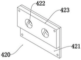
Further: driven piece includes fixed plate and upset action board, the upset action board is installed on the outer wall of fixed plate, and the fixed plate is installed on the tip outer wall of transporting the unit, the inner wall of upset action board is equipped with the perforation, and the fenestrate inboard is equipped with passive groove.
Further: the shaft side of the connecting shaft is provided with a convex block which is connected between the groove walls of the driven groove in a sliding manner, and the driven groove is of a spiral line structure.
Further: the unit of transporting includes pneumatic cylinder, connecting seat and rocking arm, the bottom of rocking arm has the push pedal through the hub connection, and the piston rod one end of pneumatic cylinder is installed on the one end outer wall of push pedal, there is the auxiliary arm top one side of connecting seat through the hub connection, and the tip of auxiliary arm and the end connection of rocking arm are to same transport the seat, and the fixed plate is installed on the outer wall of transporting the seat.
Further: and the bottom side of the connecting seat is provided with an adjusting mechanism, and the adjusting mechanism is used for driving the transfer unit to switch between the positions of the first conveying mechanism, the second conveying mechanism and the assembling mechanism.
Further, the method comprises the following steps: the adjusting mechanism comprises a rotating unit and a movable sliding rail, the bottom side of the rotating unit is connected to the movable sliding rail in a sliding mode, the rotating unit comprises a rotating motor and a rotating seat, an output shaft of the rotating motor is connected with a driving gear, a gear ring is arranged on the inner side of the rotating seat, and the rotating motor drives the rotating seat to rotate through the driving gear and the gear ring.
Further, the method comprises the following steps: and the tail ends of the first conveying mechanism and the second conveying mechanism are provided with limiting frames, and the limiting frames are of V-shaped structures.
Further, the method comprises the following steps: the first conveying mechanism and the second conveying mechanism both comprise a first rack, a transmission roller set and a conveying belt, the transmission roller set is installed on the inner wall of the first rack, the conveying belt is installed on the outer wall of the transmission roller set, and one of the transmission roller set is connected with a motor used for conveying driving.
Further, the method comprises the following steps: the elevating platform is installed to the bottom of equipment mechanism, and the elevating platform is close to the unit of transporting can one end along the plummet to reciprocating.
The use method of the turnover mechanism for the transfer is carried out according to the following steps:
s1: the base and the assembly parts in the workpiece are input to the middle through the first conveying mechanism and the second conveying mechanism, the base is horizontally placed on the belt surface of the conveying belt, when the base is conveyed to the inner side wall of the limiting frame, the limiting frame with the V-shaped structure centers the base, and the workpiece is transferred through the transferring unit;
s2: firstly, transferring a base, wherein the base is positioned on the inner side of a limiting frame of a first conveying mechanism, transferring the base by using a transferring unit, a hydraulic cylinder pushes a push plate, the push plate drives a rotating arm to rotate downwards, a clamping and overturning unit at the end part of the rotating arm is driven to rotate downwards, a clamp at the front end of the rotating arm is used for clamping the base, then, the push plate is pulled back, the rotating arm of the pushing plate is driven to rotate reversely, the clamp end is driven by the rotating arm to swing onto an assembling belt of an assembling mechanism, a mounting seat is arranged on the assembling belt, a groove for fixing the base is arranged in the mounting seat, and after the base is placed in the groove, the transferring unit is reset;
s3: then, a rotating motor is used for driving the rotating disc to rotate, the rotating disc rotates ninety degrees, the clamp end is the same as the clamping transferring base in the S2, a transferring part is clamped and fixed, then in the process of pulling back, the rotating disc rotates ninety degrees in the reverse direction, the rotating arm is reset to the same axial direction with the assembling mechanism, meanwhile, when the rotating disc is transferred to the upper part of the mounting base, a push rod motor works to drive the clamp end to rotate 135 degrees around the axial direction of an output shaft of the push rod motor, the end part of the assembling part at the moment corresponds to the port part of a mounting sleeve on the base, and in the process of swinging, the assembling part is inserted into the mounting sleeve from top to bottom;
s4: meanwhile, in the process that the assembly part is inserted into the mounting sleeve from top to bottom, the front end of the lifting table vertically moves upwards along the lead, the base end is jacked into the assembly part to realize assembly, then the lifting table is restored to be horizontal, the base is separated from the mounting seat and clamped by the clamp, the push rod motor retracts to drive the assembled transfer workpiece to rotate 135 degrees, and then the transfer workpiece is placed on the transmission belt to be transmitted out;
s5: in the assembling process, the drive of assembly band and drive belt is switched and is detected through the photoelectric detection door of side direction, and the base after the assembly breaks away from the mount pad, and the assembly band is to stopping the operation, and the drive belt begins the operation, realizes the transportation output of assembly part.
The invention has the beneficial effects that:
this tilting mechanism is used for transporting and the upset on the transfer chain, a spare part for assembling specific angle or specific cooperation port, it is spacing to spare part through spacing frame, fix a position to the clamping position who transports anchor clamps, through turning to and sector swing, realize the switching between a plurality of conveyer belts, and utilize elevating platform and sector swing action to form an assembly to the state of inserting, improve assembly precision and efficiency, realized transporting and changeing and join in marriage synchronous completion, liberation labour is simultaneously, assembly precision still promotes to some extent.
Drawings
FIG. 1 is a schematic perspective view of a transfer mechanism and a method for using the same according to the present invention;
FIG. 2 is a schematic view of the conveyor mechanism of FIG. 1;
FIG. 3 is a schematic view of the assembly mechanism of FIG. 1;
FIG. 4 is a schematic view of the clamping and flipping unit shown in FIG. 1;
FIG. 5 is a schematic view of the structure of the passive component in FIG. 4;
FIG. 6 is a schematic structural diagram of a transfer turnover mechanism and a work piece transferred by using the transfer turnover mechanism;
fig. 7 is a schematic axial view of the structure of fig. 6.
In the figure: 100. transferring the workpiece; 110. a base; 120. an assembly member; 200. a first conveying mechanism; 300. a transfer unit; 310. a hydraulic cylinder; 320. a connecting seat; 330. a rotating arm; 400. a clamping and overturning unit; 410. a push rod motor; 420. a driven member; 421. a fixing plate; 422. a passive tank; 423. turning over the action plate; 430. a drive motor; 440. a clamping block; 500. an adjustment mechanism; 510. moving the slide rail; 520. a rotating unit; 521. rotating the motor; 522. a turntable; 600. a second conveying mechanism; 610. a first frame; 620. a drive roller set; 630. a conveyor belt; 640. a limiting frame; 700. an assembly mechanism; 710. a transmission belt; 720. assembling the tape; 730. a photoelectric detection gate; 740. a second frame; 800. a mounting base; 900. a lifting platform.
Detailed Description
The subject matter described herein will now be discussed with reference to example embodiments. It should be understood that these embodiments are discussed only to enable those skilled in the art to better understand and thereby implement the subject matter described herein, and are not intended to limit the scope, applicability, or examples set forth in the claims. Changes may be made in the function and arrangement of elements discussed without departing from the scope of the disclosure. Various examples may omit, substitute, or add various procedures or components as necessary. In addition, features described with respect to some examples may also be combined in other examples.
Example one
Referring to fig. 1 to 7, a transfer turnover mechanism and a method for using the same include a conveyor line and a transfer unit 300 disposed between the conveyor line, where the conveyor line is used to convey a transferred workpiece 100, the transferred workpiece 100 includes a base 110 and an assembly member 120, a mounting sleeve extends from a top end of the base 110, the mounting sleeve is in a "7" shape, a cross section of the assembly member 120 is in a "T" shape, an end of the assembly member 120 is inserted into an interior of the mounting sleeve, the conveyor line includes a first conveying mechanism 200 and a second conveying mechanism 600 for conveying the base 110 and the assembly member 120, respectively, and an assembly mechanism 700 for assembling the base 110 and the assembly member 120, a conveying direction of the first conveying mechanism 200 and a conveying direction of the second conveying mechanism 600 are consistent, and a conveying direction of the assembly mechanism 700 is perpendicular to a conveying direction of the first conveying mechanism 200 and the second conveying mechanism 600, the transfer unit 300 is disposed between the first conveying mechanism 200 and the second conveying mechanism 600, and the assembly mechanism 700, and the transfer unit 300 is used to transfer the base 110 and the assembly member 120 from the conveyor line to the assembly mechanism 700;
the clamping and overturning unit 400 is mounted at the top end of the transfer unit 300, the clamping and overturning unit 400 is used for clamping the base 110 and the assembly member 120, the base 110 is mounted in the mounting seat 800 on the assembly mechanism 700, and the end part of the assembly member 120 is mounted in the mounting sleeve of the base 110.
The clamping and overturning unit 400 includes a push rod motor 410, a driven member 420, and a clamp, wherein a connecting shaft is installed at an output shaft of the push rod motor 410, an end of the connecting shaft is assembled to an inside of the driven member 420, and the clamp is installed at a shaft end of the connecting shaft.
It should be added that the clamp includes a driving motor 430 and a clamping block 440, a rack is installed at an end of the clamping block 440, a driving gear is installed at an output shaft of the driving motor 430, the driving gear and the rack are connected in a meshing manner, the driving motor 430 rotates to drive the driving gear to rotate, the racks on two sides move along opposite directions or opposite directions to drive the clamping block 440 to perform clamping or loosening actions;
the driven member 420 includes a fixing plate 421 and a reverse acting plate 423, the reverse acting plate 423 is installed on an outer wall of the fixing plate 421, the fixing plate 421 is installed on an outer wall of an end portion of the transferring unit 300, an inner wall of the reverse acting plate 423 is provided with a through hole, and a driven groove 422 is provided inside the through hole.
The shaft side of the connecting shaft is provided with a convex block which is connected between the groove walls of the passive groove 422 in a sliding manner, and the passive groove 422 is in a spiral line structure.
The bottom side of the connecting seat 320 is provided with an adjusting mechanism 500, and the adjusting mechanism 500 is used for driving the transferring unit 300 to switch between the positions of the first conveying mechanism 200, the second conveying mechanism 600 and the assembling mechanism 700.
The adjusting mechanism 500 comprises a rotating unit 520 and a movable sliding rail 510, the bottom side of the rotating unit 520 is slidably connected to the movable sliding rail 510, the rotating unit 520 comprises a rotating motor 521 and a rotating seat, the output shaft of the rotating motor 521 is connected with a driving gear, a toothed ring is arranged on the inner side of the rotating seat, and the rotating motor 521 drives the rotating seat to rotate through the driving gear and the toothed ring.
The ends of the first conveying mechanism 200 and the second conveying mechanism 600 are both provided with a limiting frame 640, and the limiting frame 640 is of a V-shaped structure.
The first conveying mechanism 200 and the second conveying mechanism 600 each further include a first frame 610, a driving roller set 620 and a conveying belt 630, the driving roller set 620 is mounted on the inner wall of the first frame 610, the conveying belt 630 is mounted on the outer wall of the driving roller set 620, and one of the driving roller sets 620 is connected with a motor for conveying driving.
The lifting platform 900 is installed at the bottom end of the assembling mechanism 700, and one end of the lifting platform 900, which is close to the transfer unit 300, can move up and down along the plumb direction.
It should be added that, the lifting platform 900 includes a second frame 740, the inner side walls of both sides of the second frame 740 are both provided with the photoelectric detection door 730, the inner side of the second frame 740 is provided with the transmission belt 710, and the transmission belt 710 is used for outputting the assembled workpiece;
the using method of the transfer turnover mechanism is carried out according to the following steps:
s1: the base 110 and the assembly member 120 in the workpiece are conveyed in the middle by the first conveying mechanism 200 and the second conveying mechanism 600, the base 110 is horizontally placed on the belt surface of the conveying belt 630, when the base is conveyed to the inner side wall of the limiting frame 640, the limiting frame 640 in the V-shaped structure centers the base, and the workpiece 100 is conveyed by the conveying unit 300;
it should be added that, the top end of the base 110 is an extending portion, i.e. a mounting sleeve, and an included angle of 45 ° is formed between the end of the mounting sleeve and the vertical direction;
s2: firstly, transferring the base 110, wherein the base 110 is positioned on the inner side of the limiting frame 640 of the first conveying mechanism 200, transferring the base 110 by using the transferring unit 300, pushing a push plate by using a hydraulic cylinder 310, the push plate drives a rotating arm 330 to rotate downwards, the clamping and overturning unit 400 at the end part of the rotating arm 330 is driven to rotate downwards, the base 110 is clamped by using a clamp at the front end of the rotating arm, then, the push plate is pulled back, so that the rotating arm 330 rotates reversely, the rotating arm 330 drives the clamp end to swing to an assembling belt 720 of an assembling mechanism 700, a mounting seat 800 is arranged on the assembling belt 720, a groove for fixing the base 110 is arranged in the mounting seat 800, and after the base 110 is placed in the groove, the transferring unit 300 resets;
it should be added that, in the first conveying mechanism 200 and the second conveying mechanism 600, the motor drives the roller bodies in the transmission roller set 620 to drive the conveying belt 630 to transmit, so as to form a conveying belt 630 surface;
s3: then, the rotating motor 521 is used for driving the rotating disc 522 to rotate, the rotating disc 522 rotates ninety degrees, the clamp end is the same as the clamping and transferring base 110 in S2, the transferring part is clamped and fixed, then in the pulling process, the rotating disc 522 rotates ninety degrees in the reverse direction, the rotating arm 330 is reset to the direction of the same axis as the assembling mechanism 700, meanwhile, when the transferring part is arranged above the mounting seat 800, the push rod motor 410 works to drive the clamp end to rotate 135 degrees axially around the output shaft of the push rod motor 410, the end part of the assembling part 120 at the moment corresponds to the port of the mounting sleeve on the base 110, and in the swinging process, the assembling part 120 is inserted into the mounting sleeve from top to bottom;
s4: meanwhile, in the process that the assembly part 120 is inserted into the mounting sleeve from top to bottom, the front end of the lifting table 900 moves upwards vertically along the lead, the end of the base 110 is jacked into the assembly part 120 to achieve assembly, then the lifting table 900 recovers to be horizontal, the base 110 is separated from the mounting seat 800 and clamped by a clamp, the push rod motor 410 retracts at the moment to drive the assembled transfer workpiece 100 to rotate 135 degrees, and then the transfer workpiece is placed on the transmission belt 710 to be transmitted out;
s5: in the assembly process, the driving switching of the assembly belt 720 and the driving belt 710 is detected through the lateral photoelectric detection door 730, the base 110 is separated from the mounting seat 800 after the assembly, the assembly belt 720 stops working, the driving belt 710 starts working, and the transfer output of the assembly 120 is realized.
The embodiments of the present invention have been described with reference to the drawings, but the present invention is not limited to the above-mentioned specific embodiments, which are only illustrative and not restrictive, and those skilled in the art can make many forms without departing from the spirit and scope of the present invention and the protection scope of the claims.
Claims (10)
1. The transfer turnover mechanism comprises conveying lines and a transfer unit (300) arranged between the conveying lines, and is characterized in that the conveying lines are used for conveying transfer workpieces (100), each transfer workpiece (100) comprises a base (110) and an assembly part (120), an installation sleeve extends from the top end of the base (110), the installation sleeve is of a 7-shaped structure, the cross section of the assembly part (120) is of a T-shaped structure, the end part of the assembly part (120) is inserted into the installation sleeve, each conveying line comprises a first conveying mechanism (200) and a second conveying mechanism (600) used for conveying the base (110) and the assembly part (120) respectively, and an assembling mechanism (700) used for assembling the base (110) and the assembly part (120), the conveying directions of the first conveying mechanism (200) and the second conveying mechanism (600) are consistent, the conveying direction of the assembling mechanism (700) is perpendicular to the conveying directions of the first conveying mechanism (200) and the second conveying mechanism (600), the assembling mechanism (700), and the transfer unit (300) is arranged between the first conveying mechanism (200) and the second conveying mechanism (600), the assembling mechanism (600), and the assembly part (700) and the transfer unit (300) is used for transferring the base (100) to the assembly part (700);
the clamping and overturning device is characterized in that the clamping and overturning unit (400) is installed at the top end of the transferring unit (300), the clamping and overturning unit (400) is used for clamping the base (110) and the assembly part (120), the base (110) is installed in the installation seat (800) on the assembling mechanism (700), and the end part of the assembly part (120) is installed in the installation sleeve of the base (110).
2. The transfer turnover mechanism and the using method thereof as claimed in claim 1, wherein the clamping turnover unit (400) comprises a push rod motor (410), a driven member (420) and a clamp, wherein an output shaft of the push rod motor (410) is provided with a connecting shaft, an end of the connecting shaft is assembled inside the driven member (420), and the clamp is arranged at an end of the connecting shaft.
3. The turnover mechanism for transfer of claim 1, wherein the driven member (420) comprises a fixed plate (421) and a turnover plate (423), the turnover plate (423) is installed on an outer wall of the fixed plate (421), the fixed plate (421) is installed on an outer wall of an end portion of the transfer unit (300), an inner wall of the turnover plate (423) is provided with a through hole, and a driven groove (422) is formed inside the through hole.
4. A turnover mechanism and its usage in transfer of claim 1, wherein the connecting shaft has a protrusion at its axial side, and the protrusion is slidably connected between the walls of the passive slot (422), and the passive slot (422) has a helical structure.
5. The turnover mechanism for transit use according to claim 1, wherein the transfer unit (300) comprises a hydraulic cylinder (310), a connecting seat (320) and a rotating arm (330), the bottom end of the rotating arm (330) is connected with a push plate through a shaft, one end of a piston rod of the hydraulic cylinder (310) is installed on the outer wall of one end of the push plate, one side of the top end of the connecting seat (320) is connected with an auxiliary arm through a shaft, the end of the auxiliary arm and the end of the rotating arm (330) are connected to the same transfer seat, and a fixing plate (421) is installed on the outer wall of the transfer seat.
6. The turnover mechanism and its use method as claimed in claim 1, wherein the bottom side of the connecting base (320) is provided with an adjusting mechanism (500), and the adjusting mechanism (500) is used to drive the transfer unit (300) to switch between the positions of the first conveying mechanism (200), the second conveying mechanism (600) and the assembling mechanism (700).
7. The turnover mechanism for transit use as claimed in claim 1, wherein the adjustment mechanism (500) comprises a rotation unit (520) and a movable sliding rail (510), the bottom side of the rotation unit (520) is slidably connected to the movable sliding rail (510), the rotation unit (520) comprises a rotation motor (521) and a rotation seat, the output shaft of the rotation motor (521) is connected to a driving gear, the inner side of the rotation seat is provided with a toothed ring, and the rotation motor (521) drives the rotation seat to rotate through the driving gear and the toothed ring.
8. The turnover mechanism for transit use of claim 1, wherein the first conveying mechanism (200) and the second conveying mechanism (600) are provided with a limiting frame (640) at the ends, and the limiting frame (640) is of a V-shaped structure.
9. The transfer turnover mechanism and the use method thereof as claimed in claim 1, wherein each of the first conveying mechanism (200) and the second conveying mechanism (600) further comprises a first frame (610), a driving roller set (620) and a conveying belt (630), the driving roller set (620) is mounted on the inner wall of the first frame (610), the conveying belt (630) is mounted on the outer wall of the driving roller set (620), and one of the driving roller sets (620) is connected with a motor for conveying and driving.
10. A transfer turning mechanism and a method of using the same as claimed in any one of claims 1 to 9, the method of using the transfer turning mechanism is performed according to the steps of:
s1: a base (110) and an assembly part (120) in a workpiece are conveyed inwards through a first conveying mechanism (200) and a second conveying mechanism (600), the base (110) is horizontally placed on the belt surface of a conveying belt (630), when the base is conveyed to the inner side wall of a limiting frame (640), the limiting frame (640) of a V-shaped structure centers the base, and the workpiece (100) is conveyed through a conveying unit (300);
s2: firstly, transferring a base (110), wherein the base (110) is positioned on the inner side of a limiting frame (640) of a first conveying mechanism (200), the base (110) is transferred by using a transferring unit (300), a push plate is pushed by a hydraulic cylinder (310), the push plate drives a rotating arm (330) to rotate downwards, a clamping and overturning unit (400) at the end part of the rotating arm (330) is driven to rotate downwards, the base (110) is clamped by using a clamp at the front end of the clamping and overturning unit, then the push plate is pulled back, the rotating arm (330) rotates reversely, the rotating arm (330) drives the clamp end to swing to an assembling belt (720) of an assembling mechanism (700), a mounting seat (800) is installed on the assembling belt (720), a groove for fixing the base (110) is arranged in the mounting seat (800), and the transferring unit (300) resets after the base (110) is placed in the groove;
s3: then, a rotating motor (521) is used for driving the rotating disc (522) to rotate, the rotating disc (522) rotates ninety degrees, the clamp end is the same as the clamping and transferring base (110) in the S2, the transferring part is clamped and fixed, then in the pulling process, the rotating disc (522) rotates ninety degrees in the reverse direction, the rotating arm (330) is reset to the same axial direction with the assembling mechanism (700), meanwhile, when the transferring part is transferred to the upper part of the mounting seat (800), the push rod motor (410) works to drive the clamp end to rotate 135 degrees around the axial direction of an output shaft of the push rod motor (410), the end part of the assembling part (120) corresponds to the port part of the mounting sleeve on the base (110), and in the swinging process, the assembling part (120) is inserted into the mounting sleeve from top to bottom;
s4: meanwhile, in the process that the assembly part (120) is inserted into the mounting sleeve from top to bottom, the front end of the lifting table (900) moves upwards vertically along the lead, the end of the base (110) is jacked into the assembly part (120) to achieve assembly, then the lifting table (900) returns to the horizontal state, the base (110) is separated from the mounting seat (800) at the moment and is clamped by a clamp, the push rod motor (410) retracts at the moment to drive the assembled transfer workpiece (100) to rotate 135 degrees, and then the transfer workpiece is placed on the transmission belt (710) to be transmitted out;
s5: in the assembling process, the driving switching of the assembling belt (720) and the driving belt (710) is detected through the lateral photoelectric detection door (730), the base (110) after assembling is separated from the mounting seat (800), the assembling belt (720) stops working, the driving belt (710) starts working, and the transferring output of the assembling part (120) is realized.
Priority Applications (1)
| Application Number | Priority Date | Filing Date | Title |
|---|---|---|---|
| CN202211005505.8A CN115159063B (en) | 2022-08-22 | 2022-08-22 | Turnover mechanism for transit and use method thereof |
Applications Claiming Priority (1)
| Application Number | Priority Date | Filing Date | Title |
|---|---|---|---|
| CN202211005505.8A CN115159063B (en) | 2022-08-22 | 2022-08-22 | Turnover mechanism for transit and use method thereof |
Publications (2)
| Publication Number | Publication Date |
|---|---|
| CN115159063A true CN115159063A (en) | 2022-10-11 |
| CN115159063B CN115159063B (en) | 2023-12-22 |
Family
ID=83480644
Family Applications (1)
| Application Number | Title | Priority Date | Filing Date |
|---|---|---|---|
| CN202211005505.8A Active CN115159063B (en) | 2022-08-22 | 2022-08-22 | Turnover mechanism for transit and use method thereof |
Country Status (1)
| Country | Link |
|---|---|
| CN (1) | CN115159063B (en) |
Cited By (2)
| Publication number | Priority date | Publication date | Assignee | Title |
|---|---|---|---|---|
| CN117506370A (en) * | 2024-01-03 | 2024-02-06 | 凯晖科技股份有限公司 | Automatic positioning rotating shaft penetrating equipment |
| CN118723523A (en) * | 2024-08-30 | 2024-10-01 | 无锡星诺电气有限公司 | A device for transporting generator parts |
Citations (11)
| Publication number | Priority date | Publication date | Assignee | Title |
|---|---|---|---|---|
| CN105414942A (en) * | 2015-11-26 | 2016-03-23 | 苏州紫冠自动化设备有限公司 | Intelligent torque driving control mechanism and intelligent screw assembling machine adopting intelligent torque driving control mechanism |
| CN108032059A (en) * | 2017-12-26 | 2018-05-15 | 深圳市泰和安科技有限公司 | Automatic inserting apparatus of the photodetector to tube socket |
| CN110181265A (en) * | 2019-03-15 | 2019-08-30 | 丽水欧意阀门有限公司 | A kind of preparation facilities of ball valve body and valve deck |
| CN209830791U (en) * | 2019-04-15 | 2019-12-24 | 惠州欣耀精密部件有限公司 | Switch terminal material loading assembly device |
| CN111805230A (en) * | 2020-06-29 | 2020-10-23 | 浙江佛尔泰智能设备有限公司 | An automatic cross axis assembly line |
| CN112978355A (en) * | 2021-02-08 | 2021-06-18 | 苏州凯磊胜自动化科技有限公司 | On-line device and method for jumping pen clamping rod |
| CN214322475U (en) * | 2021-02-08 | 2021-10-01 | 苏州凯磊胜自动化科技有限公司 | On-line device of jumping pen holder |
| CN113878133A (en) * | 2021-10-13 | 2022-01-04 | 张传保 | Gantry type lathe workpiece clamping system |
| CN114043193A (en) * | 2021-11-12 | 2022-02-15 | 江西振扬精密机械制造有限公司 | Automatic assembly and packaging production line for cross shafts |
| CN216189145U (en) * | 2021-11-08 | 2022-04-05 | 深圳市慧星智能机电有限公司 | Turnover feeding mechanism |
| WO2022077819A1 (en) * | 2020-10-13 | 2022-04-21 | 梁浩贤 | Assembly system for seatbelt buckles |
-
2022
- 2022-08-22 CN CN202211005505.8A patent/CN115159063B/en active Active
Patent Citations (11)
| Publication number | Priority date | Publication date | Assignee | Title |
|---|---|---|---|---|
| CN105414942A (en) * | 2015-11-26 | 2016-03-23 | 苏州紫冠自动化设备有限公司 | Intelligent torque driving control mechanism and intelligent screw assembling machine adopting intelligent torque driving control mechanism |
| CN108032059A (en) * | 2017-12-26 | 2018-05-15 | 深圳市泰和安科技有限公司 | Automatic inserting apparatus of the photodetector to tube socket |
| CN110181265A (en) * | 2019-03-15 | 2019-08-30 | 丽水欧意阀门有限公司 | A kind of preparation facilities of ball valve body and valve deck |
| CN209830791U (en) * | 2019-04-15 | 2019-12-24 | 惠州欣耀精密部件有限公司 | Switch terminal material loading assembly device |
| CN111805230A (en) * | 2020-06-29 | 2020-10-23 | 浙江佛尔泰智能设备有限公司 | An automatic cross axis assembly line |
| WO2022077819A1 (en) * | 2020-10-13 | 2022-04-21 | 梁浩贤 | Assembly system for seatbelt buckles |
| CN112978355A (en) * | 2021-02-08 | 2021-06-18 | 苏州凯磊胜自动化科技有限公司 | On-line device and method for jumping pen clamping rod |
| CN214322475U (en) * | 2021-02-08 | 2021-10-01 | 苏州凯磊胜自动化科技有限公司 | On-line device of jumping pen holder |
| CN113878133A (en) * | 2021-10-13 | 2022-01-04 | 张传保 | Gantry type lathe workpiece clamping system |
| CN216189145U (en) * | 2021-11-08 | 2022-04-05 | 深圳市慧星智能机电有限公司 | Turnover feeding mechanism |
| CN114043193A (en) * | 2021-11-12 | 2022-02-15 | 江西振扬精密机械制造有限公司 | Automatic assembly and packaging production line for cross shafts |
Cited By (4)
| Publication number | Priority date | Publication date | Assignee | Title |
|---|---|---|---|---|
| CN117506370A (en) * | 2024-01-03 | 2024-02-06 | 凯晖科技股份有限公司 | Automatic positioning rotating shaft penetrating equipment |
| CN117506370B (en) * | 2024-01-03 | 2024-03-08 | 凯晖科技股份有限公司 | Automatic positioning rotating shaft penetrating equipment |
| CN118723523A (en) * | 2024-08-30 | 2024-10-01 | 无锡星诺电气有限公司 | A device for transporting generator parts |
| CN118723523B (en) * | 2024-08-30 | 2024-12-27 | 无锡星诺电气有限公司 | A device for transporting generator parts |
Also Published As
| Publication number | Publication date |
|---|---|
| CN115159063B (en) | 2023-12-22 |
Similar Documents
| Publication | Publication Date | Title |
|---|---|---|
| CN112374106A (en) | Automatic transfer, turnover and conveying equipment | |
| CN115159063B (en) | Turnover mechanism for transit and use method thereof | |
| CN214454714U (en) | Automatic turnover device for sand box | |
| CN112209006A (en) | A belt type jig conveying mechanism | |
| CN112692815A (en) | Transfer manipulator for carrying advanced manufacturing materials | |
| CN111003477A (en) | Circulation type conveying line | |
| CN210820046U (en) | Wood door four-side saw | |
| CN117680850A (en) | Laser pipe cutting machine comprising horizontal and side-hanging type three-clamping four-chuck structure | |
| JP2007520356A (en) | Conveying device for conveying a workpiece through a press device | |
| CN113523704A (en) | Section steel overturning, butting and assembling device and system | |
| CN109896242B (en) | Pallet conveying line | |
| CN213922985U (en) | Automatic transfer and flip conveying equipment | |
| CN219791590U (en) | Soft board buffer memory | |
| CN218706980U (en) | Clamp steering device and conveying equipment | |
| KR20160070480A (en) | Apparatus for transferring a pallet | |
| CN216503734U (en) | Upper and lower double-material platform mechanism | |
| CN209739943U (en) | Conveying mechanism | |
| CN115043165A (en) | Tool handling device and battery liquid injection equipment | |
| CN115070799A (en) | A fork manipulator capable of clamping and centering | |
| CN111924475A (en) | Intermittent plate conveying device and method | |
| CN217577123U (en) | Supporting plate overturning device | |
| CN223162584U (en) | Feeding mechanism for capacitor forming machine | |
| CN223133327U (en) | Lifting and transferring conveyor and conveying system | |
| CN220787019U (en) | Synchronous belt conveying device and assembly equipment | |
| CN222792062U (en) | A machine transfer robot |
Legal Events
| Date | Code | Title | Description |
|---|---|---|---|
| PB01 | Publication | ||
| PB01 | Publication | ||
| SE01 | Entry into force of request for substantive examination | ||
| SE01 | Entry into force of request for substantive examination | ||
| GR01 | Patent grant | ||
| GR01 | Patent grant |