Background
The numerical control lathe is a high-precision and high-efficiency automatic lathe, is provided with a multi-station tool turret or a power tool turret, has wide processing technological performance, can process complex workpieces such as linear cylinders, oblique cylinders, circular arcs and various threads, grooves, worms and the like, has various compensation functions such as linear interpolation, circular arc interpolation and the like, and plays a good economic effect in the batch production of complex parts.
The base of the existing lathe is generally of a planar structure, so that cutting chips generated in the machining process are easy to accumulate on a workbench, the load of the lathe is increased, the dynamic performance is poor, the lathe is worn, deformed and even damaged, the cutting chips are difficult to clean, and the guide rail protective cover can be pulled by untimely treatment, so that the guide rail is damaged and the precision of a transmission screw rod is lost.
In addition, the clamp of the main shaft and the cutter head of the cutter tower are arranged oppositely, and the cutter head can process a workpiece on the clamp through the movement of the cutter tower, but the structure enables the base of the lathe to be long as a whole, and a feeding and discharging mechanism is difficult to install in the lathe. Therefore, the feeding and discharging mechanism of the existing lathe is arranged outside the lathe, after each workpiece is machined, the feeding and discharging operation can be carried out only after the waiting door is opened, and due to the fact that the stroke of the feeding and discharging mechanism is long, for achieving smoothness of feeding and discharging actions by being matched with a numerical control lathe, multiple times of correction and debugging of a matching program are generally needed for concentricity and the like, and the feeding and discharging mechanism is complex to put into production.
Disclosure of Invention
1. Technical problem to be solved by the invention
The invention provides a turret type numerically controlled lathe, aiming at the technical problem that the feeding and discharging mechanisms of the existing lathe are arranged outside the lathe, the feeding and discharging mechanisms can be integrated in the lathe, and when the lathe leaves a factory, the relative positions of the feeding and discharging structures and a workpiece clamping structure can be adjusted and kept fixed, so that the stability of feeding and discharging actions during working is ensured, and the debugging on site is not needed.
2. Technical scheme
In order to solve the problems, the technical scheme provided by the invention is as follows:
a turret type numerical control lathe comprises a base; the spindle box is fixedly arranged on the base, a workpiece clamping structure is arranged on one side, close to the feeding and discharging structure, of the spindle box, and a workpiece clamping driving structure is arranged on one side, far away from the feeding and discharging structure, of the spindle box; the feeding and discharging structure is fixedly arranged on the base and is opposite to the spindle box; the tool turret is arranged on the base and is positioned on the upper side or the lower side of the workpiece clamping structure; the base is provided with a transverse guide rail for controlling the cutter tower to move transversely and a vertical guide rail for controlling the cutter tower to move vertically; the cutter tower comprises a cutter tower box and a cutter head, the cutter tower box is close to one side of the spindle box, and the cutter head is close to one side of the feeding and discharging structure.
Optionally, the workpiece clamping structure comprises a spindle mounted on the spindle box; the workpiece clamp is arranged at one end of the main shaft; the workpiece clamping driving structure comprises a rotary cylinder for controlling the clamping state of the workpiece clamp.
Optionally, go up unloading structure includes the arm, and install in mechanical clamping jaw on the arm still includes the supporter that is used for placing the work piece.
Optionally, the arm includes the edge the first cursor slide that work piece clamping structure and last unloading structure line direction set up to and the second cursor slide that sets up along vertical direction of height, second cursor slide slidable install in on the first cursor slide, mechanical clamping jaw pass through mechanical clamping jaw mounting bracket install in on the second cursor slide, still including being used for control the supporter control structure of supporter activity.
Optionally, the shelf control structure comprises a third slide arm arranged horizontally and perpendicular to the first slide arm.
Optionally, two or more mechanical jaws are simultaneously mounted on the mechanical jaw mounting frame.
Optionally, the processing surface of the base is an inclined surface, and the workpiece clamping structure and the turret are mounted on the inclined surface.
3. Advantageous effects
Compared with the prior art, the technical scheme provided by the invention has the following beneficial effects:
the turret in the turret type numerically controlled lathe adopts an inverted structure, the turret box is arranged on one side close to the workpiece clamping structure, enough installation space is reserved for installation of the feeding and discharging structure, the problems that the base of the lathe is long and the occupied space is too large can be solved, and the turret and the feeding and discharging mechanism need to move, so that the turret box and the feeding and discharging structure which are large in size are positioned on different sides, and cannot interfere with each other during movement; more importantly, adopt above-mentioned structural design, make go up the unloading structure can install inside same lathe housing with work piece clamping structure, when dispatching from the factory, can adjust go up the unloading structure can with work piece clamping structure's relative position and keep fixed, guarantee the precision of during operation, need not to debug on the scene, communication control mode also can be accomplished by the producer and dispatch from the factory and set for (traditional digit control machine tool needs purchase unloading structure outward, need just can guarantee its precision of during operation through complicated debugging between digit control machine tool and the unloading structure outward of buying, still need add a control system who is used for simultaneous control digit control machine tool and goes up the unloading structure simultaneously, the overall cost is higher, and all need debug the digit control machine tool again and the unloading structure's of buying outward cooperation state outward when the position of digit control machine tool is removed at every turn).
Detailed Description
In order to make the objects, technical solutions and advantages of the present invention more apparent, the present invention is further described in detail below with reference to the accompanying drawings and the detailed description. It should be understood that the detailed description and specific examples, while indicating the scope of the invention, are intended for purposes of illustration only and are not intended to limit the scope of the invention.
It will be understood that when an element is referred to as being "secured to," "disposed on," "secured to," or "disposed on" another element, it can be directly on the other element or intervening elements may also be present. When an element is referred to as being "connected" to another element, it can be directly connected to the other element or intervening elements may also be present. Further, when one element is considered to be "fixedly connected" to another element, the two elements may be fixed by way of detachable connection, or may be fixed by way of non-detachable connection, such as socket connection, snap connection, integrally formed fixation, welding, etc., which can be realized in the prior art, and thus are not cumbersome. When an element is perpendicular or nearly perpendicular to another element, it is desirable that the two elements are perpendicular, but some vertical error may exist due to manufacturing and assembly effects. The terms "vertical," "horizontal," "left," "right," and the like as used herein are for illustrative purposes only and do not represent the only embodiments.
Unless defined otherwise, all technical and scientific terms used herein have the same meaning as commonly understood by one of ordinary skill in the art to which this invention belongs. The terminology used herein in the description of the invention is for the purpose of describing particular embodiments only and is not intended to be limiting of the invention. As used herein, the term "and/or" includes any and all combinations of one or more of the associated listed items.
References to "first" and "second" in the present disclosure do not denote any particular quantity or order, but rather are used to distinguish one from another.
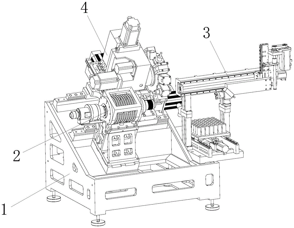
With reference to fig. 1-4, the turret-type numerically controlled lathe of the present embodiment includes a base 1; the spindle box 2 is fixedly arranged on the base, a workpiece clamping structure is arranged on one side, close to the feeding and discharging structure 3, of the spindle box 2, and a workpiece clamping driving structure is arranged on one side, far away from the feeding and discharging structure 3, of the spindle box 2; the feeding and discharging structure 3 is fixedly arranged on the base 1 and is arranged opposite to the spindle box 2 in the left-right direction; a turret 4, disposed on the base 1 and located at an upper side or a lower side of the workpiece clamping structure (if the processing surface of the base 1 is an inclined surface, it is very intuitive that the turret 4 is located at the upper side or the lower side of the workpiece clamping structure, and if the processing surface of the base 1 is a plane, the turret 4 is located at the upper side or the lower side of the workpiece clamping structure and is viewed from a top-to-bottom perspective toward the processing surface of the base 1), in this embodiment, the turret 4 is located at the upper side of the workpiece clamping structure; the knife tower 4 comprises a knife tower box 41 and a cutter disc 42, and the knife tower box 41 is used for controlling the working state of the cutter disc 42; knife tower case 41 is close to one side setting of headstock 2, the blade disc 42 is close to one side setting of last unloading structure 3 still includes and is used for control the knife tower control structure of knife tower 4 removal on base 1 to the processing to the work piece is accomplished in the removal through blade disc 42, knife tower control structure is including being used for control knife tower lateral shifting's transverse guide 51, and be used for control the vertical guide 52 of knife tower vertical migration.
The turret in the turret type numerical control lathe adopts an inverted structure, the turret case 41 is arranged at one side close to the main spindle box 2, enough installation space is reserved for installing the feeding and discharging structure 3, the problems that the base of the lathe is lengthened and the occupied space is overlarge can be solved, and the turret 4 and the feeding and discharging mechanism need to move, so that the turret case 41 with large volume and the feeding and discharging structure 3 are positioned at different sides and cannot interfere with each other during movement; more importantly, adopt above-mentioned structural design, make go up unloading structure 3 can install inside same lathe housing with work piece clamping structure, when dispatching from the factory, can adjust go up unloading structure 3 can with work piece clamping structure's relative position, guarantee the precision of during operation, need not to debug on the scene, the communication control mode also can be accomplished by the producer and dispatch from the factory to set for (traditional digit control machine tool needs purchase unloading structure outward, need just can guarantee its during operation precision through complicated debugging between digit control machine tool and the last unloading structure of purchasing outward, still need add a control system who is used for simultaneous control digit control machine tool and goes up unloading structure simultaneously, the overall cost is higher, and all need debug the digit control machine tool again and purchase the cooperation state of last unloading structure outward when the position of digit control machine tool is removed at every turn).
As an alternative of the present invention, the turret control structure includes a first slide rail structure 51 disposed along a connection line of the workpiece clamping structure and the feeding and discharging structure 3 (in this embodiment, the workpiece clamping structure and the feeding and discharging structure 3 are disposed oppositely on the left and right, and the first slide rail structure 51 is disposed along the left and right horizontal direction), and a second slide rail structure 52 disposed along a direction perpendicular to the first slide rail structure 51, where the first slide rail structure 51 and the second slide rail structure 52 cooperate to control the turret 4 to move along an axial direction and a radial direction of a clamped workpiece, specifically, the second slide rail structure 52 is mounted on the first slide rail structure 51, the turret 4 is mounted on the second slide rail structure 52, the first slide rail structure 51 and the second slide rail structure 52 are both electric rails, and of course, the first slide rail structure 51 and the second slide rail structure 52 may also be common slide rail rails, and at this time, it is necessary to drive the second slide rail structure 52 to slide on the first structure 51 by an air cylinder, and the slide rail 4 on the second slide rail structure 52.
As an alternative of the present invention, the work holding structure includes a spindle 22 mounted on the spindle head 2; the workpiece clamp 23 is arranged at one end of the main shaft 22 close to the feeding and discharging structure 3; the workpiece clamping driving structure comprises a rotary cylinder 24 for controlling the clamping state of the workpiece clamp, and is used for controlling the clamping state of the workpiece clamp 23, the rotary cylinder 24 is arranged at one end of the main shaft 22, which is far away from the feeding and discharging structure 3, and the way of how the rotary cylinder 24 controls the clamping state of the workpiece clamp 23 is the prior art, so that the description is omitted here, and it is to be particularly described that, in order to make the structure of the workpiece clamping structure simpler, the main shaft box 2 is an existing electric main shaft box on the market, and can also be replaced by a common main shaft box adopting a motor and a belt pulley.
As an alternative of the present invention, a fixing seat 6 for mounting the spindle box 2 is disposed on the base 1, a triangular support structure is disposed on the fixing seat 6 to improve the overall strength of the fixing seat 6, and the present invention further includes a rotary cylinder fixing frame 7 whose two ends are respectively fixedly connected to the rotary cylinder 24 and the fixing seat 6 through a threaded structure (a fastener such as a bolt, a nut, etc.), the rotary cylinder fixing frame 7 is in an L-shaped structure, one end of the rotary cylinder fixing frame is abutted to the fixing seat 6, and the other end of the rotary cylinder fixing frame is abutted to the cylinder body of the rotary cylinder 24, and through the arrangement of the rotary cylinder fixing frame 7, the deflection of the rotary cylinder 24 during operation can be effectively inhibited, so that the connection between the rotary cylinder 24 and the medium pipe is prevented from being loosened and loosened due to excessive deflection, and once the connection between the medium pipe is loosened and loosened, a large potential safety hazard is caused.
As an alternative of the present invention, the loading and unloading structure 3 includes a robot arm 31, a mechanical clamping jaw 32 mounted on the robot arm 31, and a rack 33 for placing workpieces, where the robot arm 31 controls the mechanical clamping jaw 32 to move, so that the mechanical clamping jaw 32 grabs the workpieces on the rack 33, and conveys the workpieces to the workpiece clamping structure for fixing, and at the same time, takes the workpieces that have been processed off the workpiece clamping structure.
As an alternative of the present invention, the robot arm 31 includes a first slide arm 311 disposed along a line connecting the workpiece clamping structure and the loading and unloading structure 3 (in this embodiment, the first slide arm 311 is disposed along a horizontal direction), and a second slide arm 312 disposed along a vertical height direction, the second slide arm 312 is slidably mounted on the first slide arm 311, so that the second slide arm 312 can slide along a horizontal direction, the mechanical gripper 32 is mounted on the second slide arm 312 through a mechanical gripper mounting bracket 313, the mechanical gripper 32 can move in the horizontal direction and the vertical height direction through the first slide arm 311 and the second slide arm 312, and further includes a rack control structure for controlling the horizontal movement of the rack 33, so that the workpiece on the rack 33 is moved to a clamping station to wait for the grabbing of the mechanical gripper 32, specifically, the rack control structure includes a third slide arm 8 disposed horizontally and perpendicularly to the direction of the first slide arm 311, and naturally, the additional rack control structure may not be provided, and then another rack control slide arm 32 moving along a horizontal direction and a mechanical gripper 32 may be convenient for the grabbing of the other mechanical gripper.
As an alternative of the present invention, two or more mechanical clamping jaws 32 are simultaneously mounted on the mechanical clamping jaw mounting frame 313, and when a workpiece is clamped on one mechanical clamping jaw 32, the workpiece can be grabbed by the other mechanical clamping jaw 32, so that the loading and unloading operations can be simultaneously completed by one motion during the loading and unloading.
As an alternative of the present invention, the processing surface of the base 1 is an inclined surface, the workpiece clamping structure and the turret 4 are mounted on the inclined surface, cutting chips generated by processing can be quickly accumulated at the material collecting port to be discharged under the guidance of the inclined surface, so that the chip discharging efficiency and effect are improved, the cleanliness of the interior of the numerically controlled lathe is improved, and specifically, the inclination of the inclined surface is preferably 45 °.
The present invention and its embodiments have been described above schematically, without limitation, and what is shown in the drawings is only one of the embodiments of the present invention, and the actual structure is not limited thereto. Therefore, without departing from the spirit of the present invention, a person of ordinary skill in the art should understand that the present invention shall not be limited to the embodiments and the similar structural modes without creative design.