CN115156107A - Chip automatic test sorting machine - Google Patents
Chip automatic test sorting machine Download PDFInfo
- Publication number
- CN115156107A CN115156107A CN202210758527.5A CN202210758527A CN115156107A CN 115156107 A CN115156107 A CN 115156107A CN 202210758527 A CN202210758527 A CN 202210758527A CN 115156107 A CN115156107 A CN 115156107A
- Authority
- CN
- China
- Prior art keywords
- loading
- test
- unloading
- suction nozzle
- module
- Prior art date
- Legal status (The legal status is an assumption and is not a legal conclusion. Google has not performed a legal analysis and makes no representation as to the accuracy of the status listed.)
- Pending
Links
Images


Classifications
-
- B—PERFORMING OPERATIONS; TRANSPORTING
- B07—SEPARATING SOLIDS FROM SOLIDS; SORTING
- B07C—POSTAL SORTING; SORTING INDIVIDUAL ARTICLES, OR BULK MATERIAL FIT TO BE SORTED PIECE-MEAL, e.g. BY PICKING
- B07C5/00—Sorting according to a characteristic or feature of the articles or material being sorted, e.g. by control effected by devices which detect or measure such characteristic or feature; Sorting by manually actuated devices, e.g. switches
- B07C5/34—Sorting according to other particular properties
- B07C5/344—Sorting according to other particular properties according to electric or electromagnetic properties
-
- B—PERFORMING OPERATIONS; TRANSPORTING
- B07—SEPARATING SOLIDS FROM SOLIDS; SORTING
- B07C—POSTAL SORTING; SORTING INDIVIDUAL ARTICLES, OR BULK MATERIAL FIT TO BE SORTED PIECE-MEAL, e.g. BY PICKING
- B07C5/00—Sorting according to a characteristic or feature of the articles or material being sorted, e.g. by control effected by devices which detect or measure such characteristic or feature; Sorting by manually actuated devices, e.g. switches
- B07C5/02—Measures preceding sorting, e.g. arranging articles in a stream orientating
-
- B—PERFORMING OPERATIONS; TRANSPORTING
- B07—SEPARATING SOLIDS FROM SOLIDS; SORTING
- B07C—POSTAL SORTING; SORTING INDIVIDUAL ARTICLES, OR BULK MATERIAL FIT TO BE SORTED PIECE-MEAL, e.g. BY PICKING
- B07C5/00—Sorting according to a characteristic or feature of the articles or material being sorted, e.g. by control effected by devices which detect or measure such characteristic or feature; Sorting by manually actuated devices, e.g. switches
- B07C5/36—Sorting apparatus characterised by the means used for distribution
- B07C5/361—Processing or control devices therefor, e.g. escort memory
- B07C5/362—Separating or distributor mechanisms
-
- B—PERFORMING OPERATIONS; TRANSPORTING
- B07—SEPARATING SOLIDS FROM SOLIDS; SORTING
- B07C—POSTAL SORTING; SORTING INDIVIDUAL ARTICLES, OR BULK MATERIAL FIT TO BE SORTED PIECE-MEAL, e.g. BY PICKING
- B07C2301/00—Sorting according to destination
- B07C2301/0008—Electronic Devices, e.g. keyboard, displays
Landscapes
- Testing Of Individual Semiconductor Devices (AREA)
Abstract
本发明公开了一种芯片自动测试分选机,包括:测试机台,所述测试机台上阵列设置有多个测试模组;上下料机构,所述上下料机构设置于测试机台的侧边,用于放置芯片的料盘;飞梭机构,所述飞梭机构的一进出料端设置于上下料机构处,飞梭机构的另一进出料端设置于测试模组处;上下料机头机构,所述上下料机头机构设置于上下料机构的上方位置,用于在上下料机构与飞梭机构之间取放芯片;测试机头机构,所述测试机头机构设置于测试机台的上方位置,用于在测试模组与飞梭机构之间取放芯片。本发明能够适应不同规格的测试芯片,操作简单,安全性高,设备体积小,通过调整上下料吸嘴的间距、测试吸嘴的间距,能够满足成排芯片的取放。
The invention discloses an automatic chip testing and sorting machine, comprising: a testing machine, a plurality of test modules are arranged in an array on the testing machine; and a loading and unloading mechanism, the loading and unloading mechanism is arranged on the side of the testing machine side, the feeding tray for placing chips; shuttle mechanism, one feeding and discharging end of the shuttle mechanism is set at the loading and unloading mechanism, and the other feeding and discharging end of the shuttle mechanism is set at the test module; the loading and unloading machine The head mechanism, the upper and lower feeding head mechanism is arranged above the loading and unloading mechanism, and is used for picking and placing chips between the loading and unloading mechanism and the shuttle mechanism; the testing head mechanism, the testing head mechanism is arranged on the testing machine The upper position of the table is used to pick and place chips between the test module and the shuttle mechanism. The invention can adapt to test chips of different specifications, has simple operation, high safety, and small equipment volume.
Description
技术领域technical field
本发明涉及测试设备技术领域,尤其涉及了一种芯片自动测试分选机。The invention relates to the technical field of testing equipment, in particular to an automatic chip testing and sorting machine.
背景技术Background technique
功能测试项目是指模拟产品在现实使用条件中涉及到的各种因素对产品产生性能的情况进行相应条件加强实验的过程。The functional test project refers to the process of simulating the various factors involved in the actual use conditions of the product to carry out the corresponding condition strengthening experiments on the performance of the product.
一般来说,电子器件,无论是原件、部件、零件、整机等都需要进行测试。测试由生产厂家或一流的电子电器检测技术公司来完成,其通过测试发现产品存在的问题并且及时修改,让到达消费者手中产品的问题尽量少或提高产品可靠性。Generally speaking, electronic devices, whether they are originals, components, parts, whole machines, etc., need to be tested. The test is completed by the manufacturer or a first-class electronic and electrical testing technology company, which finds out the problems of the product through the test and revises it in time, so as to minimize the problems of the product reaching the consumers or improve the reliability of the product.
传统的芯片测试主要由人工将单一芯片放到测试设备进行测试,并由人眼观察测试芯片并对应记录测试结果,测试完成后再人工将测试芯片分类、摆盘等,生产效率低下,无法满足大规模高效生产的需求。In traditional chip testing, a single chip is manually placed in the test equipment for testing, and the test chip is observed by human eyes and the test results are recorded accordingly. The need for efficient large-scale production.
现有技术中采用机械手在芯片测试时进行上料和下料,把上下料区和测试区分开,分别通过机械手取放,上下料区的机械手从料盘取料至飞梭来回往复运动,然后测试区处的机械手从飞梭上取料至测试区进行测试,测试区在测试芯片时,对单个芯片进行测试,然后测试区的机械手将测试完的芯片取回放置飞梭上,然后飞梭运动至上下料区处,再由机械手出料,一般采用电机丝杠机构将飞梭在上下料区与测试区之间往复运送,这样只能一块飞梭来回往复运动,不能满足整个机台快速高效的需求。In the prior art, a manipulator is used for loading and unloading during chip testing, and the loading and unloading areas are separated from the testing area, and are picked and placed by the manipulator respectively. The manipulator in the test area takes the material from the shuttle to the test area for testing. When testing the chip in the test area, a single chip is tested, and then the manipulator in the test area retrieves the tested chip and places it on the shuttle, and then the shuttle It moves to the loading and unloading area, and then the manipulator discharges the material. Generally, the motor screw mechanism is used to transport the shuttle back and forth between the loading and unloading area and the testing area. In this way, only one shuttle can move back and forth, which cannot meet the speed of the entire machine. efficient demand.
为了提高生产效率,现有技术中一般通过三维模组控制机械手取放料,然后再放置在测试治具上,再将测试治具放置于测试板上进行测试,目前采用的上料方法是利用成排吸嘴逐一的吸取芯片进行上料或下料,虽然相较于人工,效率提升了不少,但存在如下缺陷:(1)针对不同规格的测试芯片,需要更换不同的测试治具,测试治具上芯片位置成排设置,测试区的测试板对芯片测试时成排测试,占用空间大,进而整个设备体积大,不方便;(2)更换不同的测试板时,需要操作人员钻进机台的里进行拆装更换,工序繁琐,安全性低;(3)芯片在上下料、测试取放时由成排吸嘴统一升降,各个吸嘴根据芯片摆放位置的间距等距上下料,这时各个吸嘴之间的间距难以调整,精度低。In order to improve production efficiency, in the prior art, a three-dimensional module is generally used to control the manipulator to take and unload materials, and then placed on the test fixture, and then the test fixture is placed on the test board for testing. The currently used feeding method is to use Rows of suction nozzles pick up chips one by one for feeding or unloading. Although the efficiency is much improved compared to manual work, it has the following defects: (1) For test chips of different specifications, different test fixtures need to be replaced, The positions of the chips on the test fixture are arranged in rows, and the test boards in the test area are tested in rows when testing the chips, which takes up a lot of space, and the whole equipment is bulky and inconvenient; (2) When changing different test boards, the operator needs to drill It is difficult to disassemble and replace in the machine table, the process is cumbersome and the safety is low; (3) The chips are lifted and lowered uniformly by rows of suction nozzles during loading and unloading, testing and picking, and each suction nozzle is equidistantly up and down according to the spacing of the chips. At this time, the distance between each nozzle is difficult to adjust and the precision is low.
发明内容SUMMARY OF THE INVENTION
针对现有技术存在的不足,本发明的目的就在于提供了一种芯片自动测试分选机,能够适应不同规格的测试芯片,操作简单,安全性高,设备体积小,通过调整上下料吸嘴的间距、测试吸嘴的间距,能够满足成排芯片的取放。Aiming at the shortcomings of the prior art, the purpose of the present invention is to provide an automatic chip testing and sorting machine, which can adapt to test chips of different specifications, is simple to operate, has high safety, and is small in size. The spacing of the test nozzles and the spacing of the test nozzles can meet the pick and place of rows of chips.
为了实现上述目的,本发明采用的技术方案是这样的:一种芯片自动测试分选机,包括:In order to achieve the above purpose, the technical solution adopted in the present invention is as follows: an automatic chip testing and sorting machine, comprising:
测试机台,所述测试机台上阵列设置有多个测试模组;a test machine, wherein a plurality of test modules are arranged in an array on the test machine;
上下料机构,所述上下料机构设置于测试机台的侧边,用于放置芯片的料盘;The loading and unloading mechanism, the loading and unloading mechanism is arranged on the side of the testing machine, and is used for placing the chip tray;
飞梭机构,所述飞梭机构的一进出料端设置于上下料机构处,飞梭机构的另一进出料端设置于测试模组处;A shuttle mechanism, one feeding and discharging end of the shuttle mechanism is set at the loading and unloading mechanism, and the other feeding and discharging end of the shuttle mechanism is set at the test module;
上下料机头机构,所述上下料机头机构设置于上下料机构的上方位置,用于在上下料机构与飞梭机构之间取放芯片;The loading and unloading head mechanism, the loading and unloading head mechanism is arranged above the loading and unloading mechanism, and is used for picking and placing chips between the loading and unloading mechanism and the shuttle mechanism;
测试机头机构,所述测试机头机构设置于测试机台的上方位置,用于在测试模组与飞梭机构之间取放芯片;a test head mechanism, the test head mechanism is arranged on the upper position of the test machine, and is used for picking and placing chips between the test module and the shuttle mechanism;
所述测试模组包括测试底板、测试板、测试治具、压块、避位模组、下压模组,测试治具设置于测试底板上,所述测试板设置于测试治具的下方位置,压块位于测试治具的上方位置,压块用于下压测试治具内的芯片与测试板相接触;所述测试治具上开设有阵列排布的芯片安装口,该芯片安装口内活动连接有芯片插口座;所述避位模组设置于测试底板上,避位模组驱动压块避开芯片插口座正上方位置或正对芯片插口座正上方位置;所述下压模组设置于测试底板上,下压模组驱动压块下压至压块与芯片插口座内的芯片相抵。The test module includes a test base plate, a test board, a test fixture, a pressing block, an avoidance module, and a pressing module. The test fixture is set on the test base plate, and the test board is set at the lower position of the test fixture. , the pressure block is located above the test fixture, and the pressure block is used to press down the chip in the test fixture to contact the test board; the test fixture is provided with an array of chip mounting openings, and the chip mounting openings move A chip socket seat is connected; the position avoidance module is arranged on the test base plate, and the position avoidance module drives the pressing block to avoid the position directly above the chip socket seat or facing the position directly above the chip socket seat; the push-down module is set On the test base plate, the pressing module drives the pressing block to press down until the pressing block is in contact with the chip in the chip socket.
作为一种优选方案,所述避位模组包括避位气缸、避位立柱,所述避位气缸水平设置,所述避位立柱的顶部与避位气缸的推杆相连接,避位立柱的底部设置于测试底板上;所述下压模组包括下压气缸、下压滑块、下压滑轨,所述下压滑轨设置于测试底板上,下压滑轨与避位气缸同轴设置;所述下压滑块的顶部与避位气缸相连接,下压滑块的底部滑动设置于下压滑轨上;所述下压气缸设置于下压滑块的侧部,下压气缸的推杆通过转接板与压块相连接。As a preferred solution, the avoidance module includes a position avoidance cylinder and a position avoidance column, the position avoidance cylinder is arranged horizontally, the top of the position avoidance column is connected with the push rod of the position avoidance cylinder, and the The bottom is arranged on the test base plate; the lower pressure module includes a lower pressure cylinder, a lower pressure slide block, and a lower pressure slide rail, the lower pressure slide rail is arranged on the test base plate, and the lower pressure slide rail is coaxial with the avoidance cylinder set; the top of the push-down slider is connected with the avoidance cylinder, and the bottom of the push-down slide block is slidably arranged on the push-down slide rail; the push-down cylinder is arranged on the side of the push-down slide block, and the push-down cylinder The push rod is connected with the pressing block through the adapter plate.
作为一种优选方案,所述测试机台包括机台机箱、测试板放置盒,所述测试底板设置于机台机箱上,所述测试板放置盒活动连接于测试底板下方位置;所述测试板设置于测试板放置盒内,所述测试板位于测试治具下方位置。As a preferred solution, the test machine includes a machine chassis and a test board placement box, the test base plate is arranged on the machine chassis, and the test board placement box is movably connected to a position below the test base plate; the test board It is arranged in the test board placement box, and the test board is located under the test fixture.
作为一种优选方案,所述测试板放置盒的两侧板开设有连接腰形孔,测试板放置盒的两侧板通过连接腰形孔分别螺接盒连接件,所述机台机箱内的测试底板下方设置有箱体连接件,箱体连接件与盒连接件通过箱包扣活动连接。As a preferred solution, the two side plates of the test board placement box are provided with connecting waist-shaped holes, and the two side plates of the test board placement box are respectively screwed to the box connectors through the connecting waist-shaped holes. A box body connecting piece is arranged under the test bottom plate, and the box body connecting piece and the box connecting piece are movably connected through the luggage buckle.
作为一种优选方案,所述上下料机头机构包括上下料吸嘴组件、吸嘴间距调节组件、上下料运动组件,上下料吸嘴组件设置于吸嘴间距调节组件上,吸嘴间距调节组件设置于上下料运动组件上,所述上下料运动组件在X向、Y向上驱动上下料吸嘴组件运动。As a preferred solution, the loading and unloading machine head mechanism includes a loading and unloading suction nozzle assembly, a suction nozzle spacing adjustment assembly, and a loading and unloading motion assembly. The loading and unloading suction nozzle assembly is arranged on the suction nozzle spacing adjustment assembly, and the suction nozzle spacing adjustment assembly It is arranged on the loading and unloading moving assembly, and the loading and unloading moving assembly drives the loading and unloading suction nozzle assembly to move in the X direction and the Y direction.
作为一种优选方案,所述上下料吸嘴组件至少有两组,每组上下料吸嘴组件包括Z向移动模组、上下料吸嘴,所述上下料吸嘴设置于Z向移动模组上,所述Z向移动模组在Z向上驱动上下料吸嘴运动。As a preferred solution, there are at least two sets of the loading and unloading suction nozzle assemblies, each set of loading and unloading suction nozzle assemblies includes a Z-direction moving module and a loading and unloading suction nozzle, and the loading and unloading suction nozzles are arranged in the Z-direction moving module Above, the Z-direction moving module drives the loading and unloading nozzles to move in the Z-direction.
作为一种优选方案,其中一个上下料吸嘴组件为基准位,另外至少一组上下料吸嘴组件为移动位,所述移动位的上下料吸嘴包括吸嘴水平导向件、吸嘴竖直限位件、吸嘴连接杆,所述吸嘴水平导向件设置于Z向移动模组上,且吸嘴水平导向件上开设有横向的腰形导向孔,所述吸嘴连接杆的一端部设置有导向部,所述上下料吸嘴设置于吸嘴连接杆的另一端部,所述吸嘴连接杆的中部设置于吸嘴竖直限位件内,所述导向部设置于腰形导向孔内做横向往复运动,所述吸嘴竖直限位件设置于吸嘴间距调节组件上。As a preferred solution, one of the loading and unloading suction nozzle assemblies is the reference position, and at least one set of the loading and unloading suction nozzle assemblies is the moving position. Limiting member and suction nozzle connecting rod, the suction nozzle horizontal guide member is arranged on the Z-direction moving module, and the suction nozzle horizontal guide member is provided with a transverse waist-shaped guide hole, one end of the suction nozzle connecting rod is A guide part is provided, the loading and unloading suction nozzle is set at the other end of the suction nozzle connecting rod, the middle part of the suction nozzle connecting rod is set in the vertical stopper of the suction nozzle, and the guide part is set on the waist guide A horizontal reciprocating movement is performed in the hole, and the vertical stopper of the suction nozzle is arranged on the nozzle spacing adjustment component.
作为一种优选方案,所述上下料吸嘴包括上下料吸嘴头、上下料缓冲件,所述上下料缓冲件设置于上下料吸嘴头与吸嘴连接杆之间。As a preferred solution, the loading and unloading suction nozzle includes a loading and unloading suction nozzle head and a loading and unloading buffer piece, and the loading and unloading buffer piece is arranged between the loading and unloading suction nozzle head and the suction nozzle connecting rod.
作为一种优选方案,所述吸嘴间距调节组件包括调节固定板、调节滑块、调节电机、调节皮带,所述调节固定板一侧与上下料吸嘴组件相连接、调节固定板另一侧与调节滑块相连接,调节滑块滑动连接于Y向移动模组上;所述调节电机连接有调节传动轮,调节皮带套设于调节传动轮上,所述吸嘴竖直限位件设置于调节皮带上。As a preferred solution, the nozzle spacing adjustment assembly includes an adjustment fixed plate, an adjustment slider, an adjustment motor, and an adjustment belt. One side of the adjustment fixed plate is connected with the loading and unloading nozzle assembly, and the other side of the adjustment fixed plate is connected. It is connected with the adjustment slider, and the adjustment slider is slidably connected to the Y-direction moving module; the adjustment motor is connected with an adjustment transmission wheel, the adjustment belt is sleeved on the adjustment transmission wheel, and the suction nozzle vertical limiter is provided on the adjustment belt.
作为一种优选方案,所述调节传动轮包括同轴设置的第一传动轮、第二传动轮,所述第一传动轮的半径大于第二传动轮,第一传动轮、第二传动轮分别套有调节皮带;与基准位相邻的移动位上下料吸嘴组件与第二传动轮的调节皮带相连接,远离基准为的移动位上下料吸嘴组件与第一传动轮的调节皮带相连接。As a preferred solution, the adjustment transmission wheel includes a coaxially arranged first transmission wheel and a second transmission wheel, the radius of the first transmission wheel is larger than that of the second transmission wheel, and the first transmission wheel and the second transmission wheel are respectively The adjusting belt is sleeved; the moving position feeding and discharging nozzle assembly adjacent to the reference position is connected with the adjusting belt of the second drive wheel, and the moving position feeding and unloading suction nozzle assembly away from the reference position is connected with the adjusting belt of the first drive wheel .
与现有技术相比,本发明的有益效果:Compared with the prior art, the beneficial effects of the present invention:
(1)可以测试不同规格的测试芯片,测试治具上芯片位置成阵列分布,占用空间小,进而整个设备体积小;(1) Test chips of different specifications can be tested, and the positions of the chips on the test fixture are distributed in an array, occupying a small space, and thus the whole device is small in size;
(2)更换不同的测试板时,操作人员只需将测试板放置盒进行拆装更换,工序简单,安全性高;(2) When replacing different test boards, the operator only needs to disassemble and replace the test board placing box, the process is simple and the safety is high;
(3)芯片在上下料、测试取放时,各个吸嘴根据芯片摆放位置的间距等距上下料,这时各个吸嘴之间的间距调整简单,精度高。(3) When the chip is loaded and unloaded, tested and placed, each suction nozzle is equidistantly loaded and unloaded according to the spacing of the chip placement. At this time, the adjustment of the spacing between the suction nozzles is simple and the precision is high.
附图说明Description of drawings
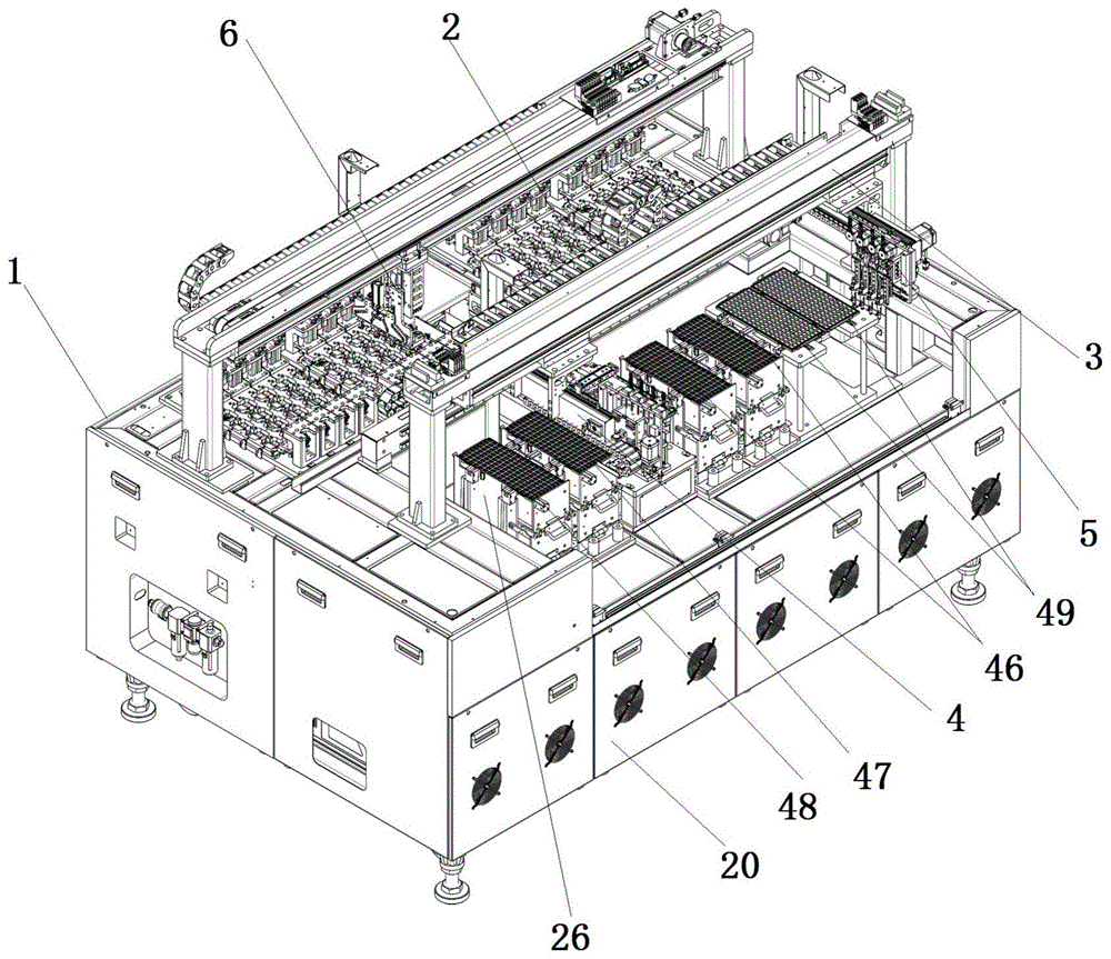
图1是本发明的整机立体图;Fig. 1 is the perspective view of the whole machine of the present invention;
图2是本发明的整机俯视图;Fig. 2 is the top view of the whole machine of the present invention;
图3是本发明中测试模组的结构示意图;Fig. 3 is the structural representation of the test module in the present invention;
图4是本发明中测试模组、测试板放置盒的连接示意图;Fig. 4 is the connection schematic diagram of test module and test board placement box in the present invention;
图5是本发明中上下料机构的结构示意图一;Fig. 5 is the structural representation one of the loading and unloading mechanism in the present invention;
图6是本发明中上下料机构的结构示意图二;Fig. 6 is the structural representation two of the loading and unloading mechanism in the present invention;
图7是本发明中料盘防落组件的结构示意图;Fig. 7 is the structural representation of the tray anti-fall assembly in the present invention;
图8是本发明中移料盘模组的结构示意图;Fig. 8 is the structural representation of the transfer tray module in the present invention;
图9是本发明中飞梭机构的结构示意图一;Fig. 9 is the structural representation one of the shuttle mechanism in the present invention;
图10是本发明中飞梭机构的结构示意图二;Fig. 10 is the structural representation two of the shuttle mechanism in the present invention;
图11是本发明中上下料机头机构的结构示意图;Fig. 11 is the structural representation of the loading and unloading head mechanism in the present invention;
图12是本发明中上下料吸嘴组件的结构示意图;12 is a schematic structural diagram of the loading and unloading nozzle assembly of the present invention;
图13是本发明中吸嘴间距调节组件的结构示意图;13 is a schematic structural diagram of the nozzle spacing adjustment assembly in the present invention;
图14是本发明中测试机头机构的结构示意图;Fig. 14 is the structural representation of the test head mechanism in the present invention;
图15是本发明中测试吸嘴组件的结构示意图一;Fig. 15 is the first structural schematic diagram of the test nozzle assembly in the present invention;
图16是本发明中测试吸嘴组件的结构示意图二;16 is a second structural schematic diagram of the test nozzle assembly in the present invention;
其中附图标识列表:测试机台1、测试模组2、上下料机构3、飞梭机构4、上下料机头机构5、测试机头机构6、测试板7、测试治具8、压块9、避位模组10、下压模组11、芯片安装口12、芯片插口座13、避位气缸14、避位立柱15、下压气缸16、下压滑块17、下压滑轨18、鱼刺部19、机台机箱20、测试板放置盒21、连接腰形孔22、盒连接件23、箱体连接件24、箱包扣25、上下料组件26、上下料料框27、上下料丝杆28、上下料螺母29、上下料电机30、上下料皮带31、料盘托板32、导向直线轴承33、上下料导向杆34、料盘定位组件35、料盘防落组件36、料盘定位气缸37、料盘定位抵挡件38、防落固定件39、防落转动件40、缓冲柱41、缓冲弹簧销42、楔形体43、光电对射感应器44、接近感应器45、分并上下料组件46、待料上下料组件47、空料上下料组件48、NG料上下料组件49、移料盘模组50、同步带直线模组51、移料升降气缸52、移料夹爪53、移料板54、移料气缸55、移料爪子56、底板57、第一滑轨58、第二滑轨59、第一导向板60、第二导向板61、飞梭驱动模组62、第一支架63、第一载料台64、第一弧线槽65、第二支架66、第二载料台67、第二直线槽68、支架滑块69、升降线轨70、飞梭电机71、飞梭传动带72、飞梭从动轮73、飞梭主动轮74、飞梭转动杆75、检测对射光电传感器76、传感器支架77、上下料吸嘴组件78、吸嘴间距调节组件79、上下料运动组件80、X向移动模组81、Y向移动模组82、Z向移动模组83、上下料吸嘴84、吸嘴水平导向件85、吸嘴竖直限位件86、吸嘴连接杆87、腰形导向孔88、导向部89、上下料吸嘴头90、上下料缓冲件91、Z向移动电机92、Z向移动滑轨93、Z向移动滑块94、Z向移动皮带95、Z向移动传动轮96、调节固定板97、调节滑块98、调节电机99、调节皮带100、调节传动轮101、第一传动轮102、第二传动轮103、测试吸嘴组件104、测试运动组件105、测试X向模组106、测试Z向模组107、测试固定板108、测试导向板109、测试气缸110、测试传动件111、测试吸嘴头112、横向导向长孔113、测试导向长孔114、测试底板115、转接板116。List of accompanying drawings:
具体实施方式Detailed ways
下面结合具体实施例对本发明作进一步描述。以下实施例仅用于更加清楚地说明本发明的技术方案,而不能以此来限制本发明的保护范围。The present invention will be further described below in conjunction with specific embodiments. The following examples are only used to illustrate the technical solutions of the present invention more clearly, and cannot be used to limit the protection scope of the present invention.
实施例:Example:
如图1~2所示,一种芯片自动测试分选机,其特征在于,包括:As shown in Figures 1-2, an automatic chip testing and sorting machine is characterized in that, it includes:
测试机台1,所述测试机台1上阵列设置有多个测试模组2;A
上下料机构3,所述上下料机构3设置于测试机台1的侧边,用于放置芯片的料盘;The loading and
飞梭机构4,所述飞梭机构4的一进出料端设置于上下料机构3处,飞梭机构4的另一进出料端设置于测试模组2处;The
上下料机头机构5,所述上下料机头机构5设置于上下料机构3的上方位置,用于在上下料机构3与飞梭机构4之间取放芯片;The loading and unloading
测试机头机构6,所述测试机头机构6设置于测试机台1的上方位置,用于在测试模组2与飞梭机构4之间取放芯片;A
如图3所示,所述测试模组2包括测试底板115、测试板7、测试治具8、压块9、避位模组10、下压模组11,测试治具8设置于测试底板115上,所述测试板7设置于测试治具8的下方位置,压块9位于测试治具8的上方位置,压块9用于下压测试治具8内的芯片与测试板7相接触;所述测试治具8上开设有阵列排布的芯片安装口12,该芯片安装口12内活动连接有芯片插口座13;所述避位模组10设置于测试底板115上,避位模组10驱动压块9避开芯片插口座13正上方位置或正对芯片插口座13正上方位置;所述下压模组11设置于测试底板115上,下压模组11驱动压块9下压至压块9与芯片插口座13内的芯片相抵。As shown in FIG. 3 , the
优选的,所述避位模组10包括避位气缸14、避位立柱15,所述避位气缸14水平设置,所述避位立柱15的顶部与避位气缸14的推杆相连接,避位立柱15的底部设置于测试底板115上;所述下压模组11包括下压气缸16、下压滑块17、下压滑轨18,所述下压滑轨18设置于测试底板115上,下压滑轨18与避位气缸14同轴设置;所述下压滑块17的顶部与避位气缸14相连接,下压滑块17的底部滑动设置于下压滑轨18上;所述下压气缸16设置于下压滑块17的侧部,下压气缸16的推杆通过转接板116与压块9相连接。Preferably, the
具体的,所述测试治具8为四列框结构,呈阵列分布放置芯片,从而使得测试模组2在测试相同芯片的前提下,面积变小,进而设备体积变小。Specifically, the
具体的,所述压块9为鱼骨状压块,下压模组11可以驱动压块9的若干鱼刺部19进而同步按压测试治具8上成排的芯片,而且避位模组10也可以驱动压块9的若干鱼刺部19同步避开芯片插口座13正上方位置或正对芯片插口座13正上方位置。Specifically, the pressing block 9 is a fishbone-shaped pressing block, and the
更为具体的,通过设置芯片插口座13,芯片插口座13为活动设置于芯片安装口12内,不同规格的芯片插口座13可以适应不同规格芯片的测试。More specifically, by disposing the
如图4所示,优选的,所述测试机台1包括机台机箱20、测试板放置盒21,所述测试底板115设置于机台机箱上,所述测试板放置盒21活动连接于测试底板115下方位置;所述测试板7设置于测试板放置盒21内,所述测试板7位于测试治具8下方位置。As shown in FIG. 4 , preferably, the
更为优选的,所述测试板放置盒21的两侧板开设有连接腰形孔22,测试板放置盒21的两侧板通过连接腰形孔22分别螺接盒连接件23,所述机台机箱20内的测试底板115下方设置有箱体连接件24,箱体连接件24与盒连接件23通过箱包扣25活动连接。More preferably, the two side plates of the test
具体的,所述箱包扣25为日常生活中公知的箱包扣25,此处不再一一赘述。Specifically, the
更为具体的,通过调节盒连接件23在连接腰形孔22内的位置,从而调整测试板放置盒21在机台机箱20的位置,安装时,只要把调节好的测试板放置盒21通过箱包扣25固定于机台机箱20内,使得测试放置盒内的测试板7位于测试治具8下方位置,从而测试板7上的探针对测试治具8内的芯片进行测试。More specifically, by adjusting the position of the
如图5~7所示,优选的,所述上下料机构3包括至少一个上下料组件26,所述上下料组件26包括上下料料框27、上下料丝杆28、上下料螺母29、上下料电机30,所述上下料电机30设置于上下料料框27的下方位置,所述上下料电机30通过上下料皮带31与上下料螺母29传动连接,所述上下料丝杆28套设于上下料螺母29内,且上下料丝杆28的上部从上下料料框27的底部贯穿设置于上下料料框27内。As shown in Figures 5-7, preferably, the loading and
具体的,所述上下料电机30通过上下料皮带31驱动上下料螺母29,进而传动上下料丝杆28旋转,从而带动上下料料框27内的料盘做升降运动。Specifically, the loading and unloading
更为优选的,所述上下料料框27内设置有料盘托板32,所述上下料丝杆28的顶部与料盘托板32相连接;所述上下料料框27的底部贯穿设置有导向直线轴承33,该导向直线轴承33内设置有上下料导向杆34;所述上下料导向杆34与上下料丝杆28平行设置,上下料导向杆34的顶部与料盘托板32相连接。More preferably, a
更为优选的,所述上下料料框27的顶部设置有料盘定位组件35、料盘防落组件36,所述料盘定位组件35包括料盘定位气缸37、料盘定位抵挡件38,所述料盘定位气缸37、料盘定位抵挡件38分别设置于上下料料框27平行的两侧部;至少一组所述料盘防落组件36设置于料盘定位气缸37同侧,至少另一组所述料盘防落组件36设置于料盘定位抵挡件38同侧;所述料盘防落组件36包括防落固定件39、防落转动件40,所述防落固定件39设置于上下料料框27上,防落固定件39内轴向贯穿设置有缓冲柱41,缓冲柱41上套设有缓冲弹簧销42;所述防落转动件40的固定端铰接于防落固定件39上,防落转动件40的移动端为朝向料盘的楔形体43,防落转动件40的本体与缓冲弹簧销42相接触。More preferably, the top of the upper and
更为优选的,所述上下料料框27的顶部设置有光电对射感应器44,上下料料框27的中部设置有接近感应器45,所述光电对射感应器44、接近感应器45用于感应上下料料框27内料盘的自由升降。More preferably, the top of the upper and
具体的,在本实施例中,上下料组件26有若干组,分别为分并上下料组件46、待料上下料组件47、空料上下料组件48、NG料上下料组件49,分并上下料组件46的料盘用于放置测试合格的芯片,待料上下料组件47的料盘用于放置待测试的芯片,空料上下料组件48用于回收空的料盘,NG料上下料组件49用于放置测试不合格的芯片。Specifically, in this embodiment, the loading and unloading
如图8所示,优选的,所述上下料组件26处设置有移料盘模组50,所述移料盘模组50包括同步带直线模组51、移料升降气缸52、移料夹爪53,所述同步带直线模组51驱动移料夹爪53在至少两个上下料组件26间运动,所述移料升降气缸52驱动移料夹爪53在上下料组件26上做升降运动,所述移料夹爪53用于上下料组件26处夹取料盘。As shown in FIG. 8 , preferably, the loading and unloading
具体的,所述移料夹爪53包括移料板54、移料气缸55、移料爪子56,所述移料气缸55固定设置于移料板54上,所述移料爪子56设置于移料气缸55的推杆上。进一步的,所述移料气缸55有四个,每两个移料气缸55的移料爪子56形成一组夹爪结构。Specifically, the material-moving
如图9~10所示,优选的,所述飞梭机构4包括底板57、第一滑轨58、第二滑轨59、第一导向板60、第二导向板61、飞梭驱动模组62,所述第一滑轨58、第二滑轨59平行设置于底板57上;所述第一滑轨58上滑动连接有第一支架63,所述第一支架63的上部设置有第一载料台64;所述第一导向板60上设置有第一弧线槽65,所述第一弧线槽65限定第一载料台64的移动路径;所述第二滑轨59上滑动连接有第二支架66,所述第二支架66的上部设置有第二载料台67;所述第二导向板61上设置有第二直线槽68,所述第二直线槽68限定第二载料台67的移动路径;所述飞梭驱动模组62分别与第一支架63、第二支架66相连接,用于驱动第一支架63与第二支架66进行相对运动。As shown in FIGS. 9-10 , preferably, the
优选的,所述第一支架63通过支架滑块69连接有升降线轨70,所述第一载料台64设置于升降线轨70的顶部;所述升降线轨70的侧壁通过设置第一滚轮(由于已经设置于构件内,故图中并未示出)与第一弧线槽65连接,所述第二支架66的侧壁通过第二滚轮(由于已经设置于构件内,故图中并未示出)与第二直线槽68连接。Preferably, the
进一步的,第一支架63移动时,带动升降线轨70在第一弧线槽65内运动,第一弧线槽65中间位置比两端位置低,因此升降线轨70沿着第一弧线槽65移动时,即沿着第一支架63上下滑动,实现升降功能。Further, when the
更进一步的,通过第二直线槽68来保证第二支架66移动的直线度,通过设置第二导向板61对第二支架66的运动路径进行限制,有利于第一载料台64与第二载料台67之间的相对运动。Furthermore, the straightness of the movement of the
优选的,所述飞梭驱动模组62包括飞梭电机71、飞梭传动带72,所述飞梭传动带72通过两个飞梭从动轮73布设于第一滑轨58、第二滑轨59之间,且飞梭传动带72分别与第一支架63、第二支架66相连接,所述飞梭电机71通过飞梭主动轮74与其中一个飞梭从动轮73相连接。Preferably, the
具体的,通过飞梭驱动模组62驱动第一载料台64与第二载料台67相对运动,从而实现第一载料台64与第二载料台67交替往复运动,从而能够快速的把待测的和已测试过的芯片往复运送于上下料机构3和测试机台1,也大大提高了检测的整体效率;通过第一导向板60限定第一载料台64的运动路线,使第一载料台64与第二载料台67在中间相遇时相互避开,使得第一载料台64与第二载料台67在同一直线上往复运动,占用空间小,使得飞梭机构4的结构更加紧凑。Specifically, the
更为具体的,通过将第一载料台64与第二载料台67设置在飞梭传动带72两侧,由于飞梭传动带72运动的特性,实现第一载料台64与第二载料台67相对运动,结构简单,易于实现。More specifically, by arranging the
进一步的,为了提高传动效率的稳定性,飞梭从动轮73通过飞梭转动杆75连接飞梭主动轮74,飞梭主动轮74通过飞梭传动带72与飞梭电机71输出端连接,飞梭电机71启动时,驱动飞梭主动轮74转动,从而带动飞梭从动轮73转动,使得飞梭传动带72绕着飞梭从动轮73转动,从而带动第一支架63与第二支架66交替往复运动。Further, in order to improve the stability of the transmission efficiency, the shuttle driven
优选的,所述飞梭机构4的进出料端设置有检测对射光电传感器76,所述第一导向板60、第二导向板61平行相对设置,所述检测对射光电传感器76通过传感器支架77设置于第一导向板60、第二导向板61上。Preferably, the feeding and discharging ends of the
具体的,上下料机构3处的检测对射光电传感器76检测第一载料台64位置,上下料机头机构5取料放入第一载料台64上,上下料机构3处的检测对射光电传感器76检测无叠料,则飞梭驱动模组62驱动第一载料台64运动到测试模组2处,测试模组2处的检测对射光电传感器76检测第一载料台64位置,测试机头机构6从第一载料台64取料放入测试模组2上;同时第二载料台67相对运动至上下料机构3处,上下料机构3处的检测对射光电传感器76检测第二载料台67位置,上下料机头机构5取料放入第二载料台67上,上下料机构3处的检测对射光电传感器76检测无叠料,则飞梭驱动模组62驱动第二载料台67运动到测试模组2处,测试模组2处的检测对射光电传感器76检测第二载料台67位置,测试机头机构6从第二载料台67取料放入测试模组2上。Specifically, the detection at the loading and
进一步的,第一载料台64与第二载料台67同时进行往复运动,在第一载料台64到测试模组2处时第二载料台67也到达上下料机构3处,从而实现取放料同步进行。Further, the
如图11~13所示,优选的,所述上下料机头机构5包括上下料吸嘴组件78、吸嘴间距调节组件79、上下料运动组件80,上下料吸嘴组件78设置于吸嘴间距调节组件79上,吸嘴间距调节组件79设置于上下料运动组件80上,所述上下料运动组件80在X向、Y向上驱动上下料吸嘴组件78运动。As shown in Figures 11-13, preferably, the loading and unloading
更为优选的,所述上下料运动组件80包括X向移动模组81、Y向移动模组82,所述Y向移动模组82设置于X向移动模组81上,所述吸嘴间距调节组件79设置于Y向移动模组82上。More preferably, the loading and
具体的,所述X向移动模组81采用本领域公知的直线模组传动,这里不再一一赘述,具体为采用线马直线电机,精度高,运行稳,速度快;所述Y向移动模组82采用本领域公知的直线模组传动,这里不再一一赘述,具体为采用松下高端FP7系列控制器和松下伺服电机控制,运行速度快、扩展性强。Specifically, the
更为优选的,所述上下料吸嘴组件78至少有两组,每组上下料吸嘴组件78包括Z向移动模组83、上下料吸嘴84,所述上下料吸嘴84设置于Z向移动模组83上,所述Z向移动模组83在Z向上驱动上下料吸嘴84运动。More preferably, there are at least two groups of the loading and unloading
具体的,其中一个上下料吸嘴组件78为基准位,另外至少一组上下料吸嘴组件78为移动位,所述移动位的上下料吸嘴84包括吸嘴水平导向件85、吸嘴竖直限位件86、吸嘴连接杆87,所述吸嘴水平导向件85设置于Z向移动模组83上,且吸嘴水平导向件85上开设有横向的腰形导向孔88,所述吸嘴连接杆87的一端部设置有导向部89,所述上下料吸嘴84设置于吸嘴连接杆87的另一端部,所述吸嘴连接杆87的中部设置于吸嘴竖直限位件86内,所述导向部89设置于腰形导向孔88内做横向往复运动,所述吸嘴竖直限位件86设置于吸嘴间距调节组件79上。Specifically, one of the loading and unloading
进一步,吸嘴间距调节组件79驱动吸嘴竖直限位件86水平往复运动,进而带动吸嘴连接杆87的导向部89在腰形导向孔88内水平往复运动,同时带动上下料吸嘴84水平往复运动,从而达到调整相邻上下料吸嘴84间距的目的。Further, the suction nozzle
更为优选的,所述上下料吸嘴84包括上下料吸嘴头90、上下料缓冲件91,所述上下料缓冲件91设置于上下料吸嘴头90与吸嘴连接杆87之间。More preferably, the loading and unloading
具体的,在本实施例中所述上下料缓冲件91为轴套内置弹簧组成,提高了稳定性,防止损坏芯片。Specifically, in this embodiment, the loading and unloading
具体的,所述Z向移动模组83包括Z向移动电机92、Z向移动滑轨93、Z向移动滑块94,所述Z向移动滑块94的底部滑动设置于Z向移动滑轨93上、Z向移动滑块94的侧部穿设有Z向移动皮带95,所述Z向移动皮带95套设于Z向移动传动轮96上,所述Z向移动电机92驱动Z向移动传动轮96上的Z向移动皮带95运动,进而带动Z向移动滑块94在Z向移动滑轨93上往复运动。Specifically, the Z-moving
进一步的,所述Z向移动滑块94与吸嘴水平导向件85相连接,进而通过吸嘴连接杆87传动带动上下料吸嘴84做升降运动。Further, the Z-
更为优选的,所述吸嘴间距调节组件79包括调节固定板97、调节滑块98、调节电机99、调节皮带100,所述调节固定板97一侧与上下料吸嘴组件78相连接、调节固定板97另一侧与调节滑块98相连接,调节滑块98滑动连接于Y向移动模组82上;所述调节电机99连接有调节传动轮101,调节皮带100套设于调节传动轮101上,所述吸嘴竖直限位件86设置于调节皮带100上。More preferably, the nozzle
具体的,所述调节传动轮101包括同轴设置的第一传动轮102、第二传动轮103,所述第一传动轮102的半径大于第二传动轮103,第一传动轮102、第二传动轮103分别套有调节皮带100;与基准位相邻的移动位上下料吸嘴组件78与第二传动轮103的调节皮带100相连接,远离基准为的移动位上下料吸嘴组件78与第一传动轮102的调节皮带100相连接。Specifically, the
进一步的,通过设置半径大小不同的同轴调节传动轮101,从而调节移动位上下料吸嘴组件78与基准位上下料吸嘴组件78之间的间距,由于较远的移动位上下料吸嘴组件78的调节传动轮101半径大,更进一步的,可以调整相邻移动位上下料吸嘴组件78的间距。Further, by setting the coaxial
如图14~16所示,优选的,所述测试机头机构6包括至少两组测试吸嘴组件104、测试运动组件105,测试吸嘴组件104设置于测试运动组件105上,进而所述测试运动组件105在X向、Z向上驱动测试吸嘴组件104运动。As shown in FIGS. 14 to 16 , preferably, the
更为优选的,所述测试运动组件105包括测试X向模组106、测试Z向模组107,所述测试Z向模组107设置于测试X向模组106上,所述测试Z向模组107为本领域公知的电机同步带传动,这里就不再一一赘述了。More preferably, the
更为优选的,每组所述测试吸嘴组件104包括测试固定板108、测试导向板109、测试气缸110、测试传动件111、测试吸嘴头112,所述测试固定板108设置于测试Z向模组107上,测试固定板108上开设有横向导向长孔113,所述测试导向板109上开设有若干呈扇形状分散的测试导向长孔114,所述测试传动件111的一端与测试吸嘴头112固定连接,测试传动件111的另一端延伸穿过横向导向长孔113设置于测试导向长孔114内,所述测试气缸110驱动测试导向板109在竖直方向上运动。More preferably, each group of the
具体的,测试气缸110通过测试导向板109在竖直方向上运动,进而位于横向导向长孔113、测试导向长孔114内的测试传动件111被带动进行横向水平运动,从而调整测试吸嘴头112的间距。Specifically, the
具体实施时,本发明的工作流程如下:先上下料机头机构5从待料上下料组件47的料盘上进行取料,放置飞梭机构4的第一载料台64或第二载料台67上,飞梭机构4输送芯片到测试模组2处,测试机头机构6取芯片放置测试模组2中进行测试,测试结束后测试机头机构6将测试模组2中的芯片取回,放置飞梭机构4的第一载料台64或第二载料台67,飞梭机构4输送芯片到上下料机构3处,取回的料如果是合格的芯片则放入分并上下料组件46的料盘内,如果是不合格的芯片则放入NG料上下料组件49的料盘内,重复以上动作,当待料上下料组件47的料盘上的芯片被取完后,移料盘模组50夹取空料盘回收至空料上下料组件48。In the specific implementation, the working process of the present invention is as follows: firstly, the unloading and unloading
以上所述仅是本发明的优选实施方式,应当指出,对于本技术领域的普通技术人员来说,在不脱离本发明技术原理的前提下,还可以做出若干改进和变形,这些改进和变形也应视为本发明的保护范围。The above are only the preferred embodiments of the present invention. It should be pointed out that for those skilled in the art, without departing from the technical principle of the present invention, several improvements and modifications can also be made. These improvements and modifications It should also be regarded as the protection scope of the present invention.
Claims (10)
Priority Applications (1)
| Application Number | Priority Date | Filing Date | Title |
|---|---|---|---|
| CN202210758527.5A CN115156107A (en) | 2022-06-29 | 2022-06-29 | Chip automatic test sorting machine |
Applications Claiming Priority (1)
| Application Number | Priority Date | Filing Date | Title |
|---|---|---|---|
| CN202210758527.5A CN115156107A (en) | 2022-06-29 | 2022-06-29 | Chip automatic test sorting machine |
Publications (1)
| Publication Number | Publication Date |
|---|---|
| CN115156107A true CN115156107A (en) | 2022-10-11 |
Family
ID=83489900
Family Applications (1)
| Application Number | Title | Priority Date | Filing Date |
|---|---|---|---|
| CN202210758527.5A Pending CN115156107A (en) | 2022-06-29 | 2022-06-29 | Chip automatic test sorting machine |
Country Status (1)
| Country | Link |
|---|---|
| CN (1) | CN115156107A (en) |
Cited By (7)
| Publication number | Priority date | Publication date | Assignee | Title |
|---|---|---|---|---|
| CN115849005A (en) * | 2022-12-29 | 2023-03-28 | 苏州乾鸣半导体设备有限公司 | Synchronous feeding and discharging equipment |
| CN115848980A (en) * | 2022-12-13 | 2023-03-28 | 苏州乾鸣半导体设备有限公司 | Chip detects with going up blanking machine |
| CN117054856A (en) * | 2023-10-10 | 2023-11-14 | 苏州元脑智能科技有限公司 | Functional test fixtures and test equipment |
| CN117102072A (en) * | 2023-10-19 | 2023-11-24 | 芯朋半导体科技(如东)有限公司 | Chip visual identification sorter with reducing suction nozzle |
| CN117139198A (en) * | 2023-10-17 | 2023-12-01 | 沛顿科技(深圳)有限公司 | A multi-type product parallel operation intelligent chip sorting machine |
| CN117206214A (en) * | 2023-11-08 | 2023-12-12 | 镇江矽佳测试技术有限公司 | An automated chip testing and sorting device and system |
| CN118904738A (en) * | 2024-10-12 | 2024-11-08 | 深圳市华拓半导体技术有限公司 | Chip detection device and detection method |
Citations (11)
| Publication number | Priority date | Publication date | Assignee | Title |
|---|---|---|---|---|
| JPH10321681A (en) * | 1997-05-19 | 1998-12-04 | Nec Corp | Wafer prober and replacement method of test board |
| CN101078737A (en) * | 2006-05-24 | 2007-11-28 | 捷智科技股份有限公司 | Connection mechanism between test fixture and machine |
| CN206366515U (en) * | 2016-12-23 | 2017-08-01 | 东莞市德胜自动化设备有限公司 | An automated testing and sorting machine |
| CN210442411U (en) * | 2019-07-25 | 2020-05-01 | 苏州韬盛电子科技有限公司 | Contact fingerprint chip machine examines tool |
| CN111198320A (en) * | 2020-02-17 | 2020-05-26 | 厦门润积集成电路技术有限公司 | Chip testing device and method |
| CN210614402U (en) * | 2019-09-20 | 2020-05-26 | 深圳市标王工业设备有限公司 | Multi-station chip testing and sorting machine |
| CN112657855A (en) * | 2020-12-28 | 2021-04-16 | 无锡市宝御达机械设备制造有限公司 | Chip detection sorting machine and detection method thereof |
| CN215248106U (en) * | 2021-07-09 | 2021-12-21 | 苏州乾鸣半导体设备有限公司 | Automatic chip testing equipment |
| CN215263804U (en) * | 2021-07-09 | 2021-12-21 | 苏州乾鸣半导体设备有限公司 | Chip array test equipment |
| CN114560292A (en) * | 2022-01-26 | 2022-05-31 | 福州派利德电子科技有限公司 | Automatic detection device and detection method for integrated circuit chip translation type sorting machine |
| CN216848044U (en) * | 2021-12-30 | 2022-06-28 | 武汉永鼎物瑞创芯技术有限公司 | A kind of optical chip automatic coupling test equipment |
-
2022
- 2022-06-29 CN CN202210758527.5A patent/CN115156107A/en active Pending
Patent Citations (11)
| Publication number | Priority date | Publication date | Assignee | Title |
|---|---|---|---|---|
| JPH10321681A (en) * | 1997-05-19 | 1998-12-04 | Nec Corp | Wafer prober and replacement method of test board |
| CN101078737A (en) * | 2006-05-24 | 2007-11-28 | 捷智科技股份有限公司 | Connection mechanism between test fixture and machine |
| CN206366515U (en) * | 2016-12-23 | 2017-08-01 | 东莞市德胜自动化设备有限公司 | An automated testing and sorting machine |
| CN210442411U (en) * | 2019-07-25 | 2020-05-01 | 苏州韬盛电子科技有限公司 | Contact fingerprint chip machine examines tool |
| CN210614402U (en) * | 2019-09-20 | 2020-05-26 | 深圳市标王工业设备有限公司 | Multi-station chip testing and sorting machine |
| CN111198320A (en) * | 2020-02-17 | 2020-05-26 | 厦门润积集成电路技术有限公司 | Chip testing device and method |
| CN112657855A (en) * | 2020-12-28 | 2021-04-16 | 无锡市宝御达机械设备制造有限公司 | Chip detection sorting machine and detection method thereof |
| CN215248106U (en) * | 2021-07-09 | 2021-12-21 | 苏州乾鸣半导体设备有限公司 | Automatic chip testing equipment |
| CN215263804U (en) * | 2021-07-09 | 2021-12-21 | 苏州乾鸣半导体设备有限公司 | Chip array test equipment |
| CN216848044U (en) * | 2021-12-30 | 2022-06-28 | 武汉永鼎物瑞创芯技术有限公司 | A kind of optical chip automatic coupling test equipment |
| CN114560292A (en) * | 2022-01-26 | 2022-05-31 | 福州派利德电子科技有限公司 | Automatic detection device and detection method for integrated circuit chip translation type sorting machine |
Cited By (10)
| Publication number | Priority date | Publication date | Assignee | Title |
|---|---|---|---|---|
| CN115848980A (en) * | 2022-12-13 | 2023-03-28 | 苏州乾鸣半导体设备有限公司 | Chip detects with going up blanking machine |
| CN115849005A (en) * | 2022-12-29 | 2023-03-28 | 苏州乾鸣半导体设备有限公司 | Synchronous feeding and discharging equipment |
| CN117054856A (en) * | 2023-10-10 | 2023-11-14 | 苏州元脑智能科技有限公司 | Functional test fixtures and test equipment |
| CN117054856B (en) * | 2023-10-10 | 2024-02-06 | 苏州元脑智能科技有限公司 | Functional test fixtures and test equipment |
| CN117139198A (en) * | 2023-10-17 | 2023-12-01 | 沛顿科技(深圳)有限公司 | A multi-type product parallel operation intelligent chip sorting machine |
| CN117102072A (en) * | 2023-10-19 | 2023-11-24 | 芯朋半导体科技(如东)有限公司 | Chip visual identification sorter with reducing suction nozzle |
| CN117102072B (en) * | 2023-10-19 | 2024-06-14 | 芯朋半导体科技(如东)有限公司 | Chip visual identification sorter with reducing suction nozzle |
| CN117206214A (en) * | 2023-11-08 | 2023-12-12 | 镇江矽佳测试技术有限公司 | An automated chip testing and sorting device and system |
| CN117206214B (en) * | 2023-11-08 | 2024-01-05 | 镇江矽佳测试技术有限公司 | An automated chip testing and sorting device and system |
| CN118904738A (en) * | 2024-10-12 | 2024-11-08 | 深圳市华拓半导体技术有限公司 | Chip detection device and detection method |
Similar Documents
| Publication | Publication Date | Title |
|---|---|---|
| CN113794083A (en) | Automatic pin inserting equipment for carrier | |
| CN215248106U (en) | Automatic chip testing equipment | |
| WO2022021493A1 (en) | Flatness testing device for solar panel installation of photovoltaic system, and testing method thereof | |
| WO2023071319A1 (en) | Stacked tray separating and feeding apparatus | |
| CN112466797A (en) | Chip assembly feeding and discharging machine | |
| CN114653622A (en) | Control method of LED and semiconductor laser chip sorting machine and sorting machine | |
| CN222118022U (en) | A copper substrate automatic feeding device | |
| CN216085670U (en) | Automatic pin inserting equipment for carrier | |
| CN213691982U (en) | A chip assembly loading and unloading machine | |
| CN117718254A (en) | Full-automatic shielding case intelligent monitoring screening plant | |
| CN115849005A (en) | Synchronous feeding and discharging equipment | |
| CN213943959U (en) | PCB board test machine | |
| CN217433624U (en) | Automatic assembling and testing production line for server mainboard | |
| CN205353301U (en) | Accurate electron base plate function automatic checkout device of polycell formula | |
| CN214421761U (en) | Automatic feeding and discharging equipment | |
| CN213210365U (en) | Double-layer type PCB testing device | |
| CN223000189U (en) | CNC lathe loading and unloading processing equipment | |
| CN113399313A (en) | Voltage internal resistance test machine | |
| CN211100210U (en) | An automatic positioning and conveying detection mechanism for ceramic sheets | |
| CN210117000U (en) | Automatic carrying and testing device for notebook battery production | |
| CN118255015A (en) | Copper substrate automatic feeding device and feeding method | |
| CN214732580U (en) | Automatic tool apron elasticity test equipment | |
| CN212652205U (en) | A chip capacitor testing device | |
| CN115921360A (en) | Controllable multi-shaft variable-pitch pickup device of test sorting machine and operation equipment | |
| CN114669888A (en) | Laser etching machine for surface of circuit main board |
Legal Events
| Date | Code | Title | Description |
|---|---|---|---|
| PB01 | Publication | ||
| PB01 | Publication | ||
| SE01 | Entry into force of request for substantive examination | ||
| SE01 | Entry into force of request for substantive examination | ||
| RJ01 | Rejection of invention patent application after publication | ||
| RJ01 | Rejection of invention patent application after publication |
Application publication date: 20221011 |