Security protection equipment for intelligent building
Technical Field
The invention belongs to the technical field of security equipment, and particularly relates to security equipment for an intelligent building.
Background
The intelligent building is a developing concept, and contents are continuously updated and supplemented along with the progress of scientific technology and the change of functional requirements of people. The purpose of realizing building intelligence is to create a safe, convenient, comfortable, efficient and reasonable living or working environment with low investment and low energy consumption for users, and any facility and system arranged in a building are subject to the goal, otherwise, the building intelligence is meaningless.
The garage safety monitoring system is an important component of an intelligent building, can directly watch the condition of a monitored place through a camera and auxiliary equipment (lenses and the like) thereof, and can record all or part of images of the monitored place, thereby providing convenient conditions and important basis for processing certain events in the future.
However, the existing garage safety monitoring system also has some disadvantages, for example, cameras are fixedly installed, so that in order to monitor a large-area garage, a large number of cameras need to be installed, and the garage can be fully covered by a shooting range.
Disclosure of Invention
The invention aims to: the intelligent building security equipment can automatically rotate the camera along with the movement of a vehicle, so that the shooting is clearer, the shooting range can be enlarged, and the using quantity of the camera is reduced.
In order to achieve the technical purpose, the technical scheme adopted by the invention is as follows:
a security device for intelligent buildings comprises a camera, a power mechanism, a locking mechanism and a rotating mechanism, wherein the camera is installed on the rotating mechanism, the rotating mechanism is installed on a wall, the power mechanism and the locking mechanism are installed underground, and the locking mechanism is connected with the rotating mechanism;
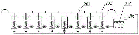
power unit includes a plurality of power unit, and wherein every power unit includes the pneumatic cylinder again, the pneumatic cylinder is installed underground, the pneumatic cylinder in-connection has the piston, be connected with first spring between piston bottom and the pneumatic cylinder bottom, be connected with the piston rod on the piston, the piston rod top is connected with the clamp plate, the clamp plate top flushes with ground, the pneumatic cylinder is connected with the feed liquor branch pipe and goes out the liquid branch pipe, be connected with the feed liquor check valve on the feed liquor branch pipe, be connected with out the liquid check valve on the play liquid branch pipe, the liquid storage pot is still installed to the underground, be connected with the liquid outlet of liquid storage pot through the feed liquor person in charge behind every power unit's the feed liquor branch pipe intercommunication, be connected with slewing mechanism through going out the liquid person in charge behind every power unit's the play liquid branch pipe intercommunication. The power mechanism is driven without additional electric energy, and the mode of utilizing the weight of the automobile is adopted, so that the electric energy can be saved.
The rotating mechanism further comprises a box body, the box body is fixedly mounted on a wall through a mounting frame, a first rotating shaft is connected in the box body in a rotating mode, a hydraulic motor and a driving bevel gear are connected to the first rotating shaft, the end face of the driving bevel gear is connected with a first clamping block, the hydraulic motor is fixedly connected to the first rotating shaft, a liquid inlet of the hydraulic motor is communicated with a liquid outlet main pipe, a liquid outlet of the hydraulic motor is communicated with a liquid inlet of a liquid storage tank, the driving bevel gear is sleeved on the first rotating shaft in an empty mode, the middle section of the first rotating shaft is of a spline shaft structure, a clutch disc is connected to the spline shaft structure, a first clamping groove is formed in the end face of the clutch disc, the clutch disc is connected with a poking disc, a poking rod and a fixed pulley are further connected to the box body in a rotating mode, the poking rod is connected with the box body through a torsion spring, one end of the poking rod is connected with a shifting fork, the shifting fork is located in the middle of the poking disc, the other end of the poking rod is connected with a first pull rope, and the first pull rope is connected with a locking mechanism after bypassing the fixed pulley.
Further inject, still be connected with the second pivot in the box, be connected with driven bevel gear and third gear in the second pivot, driven bevel gear and drive bevel gear meshing, still install the rack spout in the box, sliding connection has the third rack in the rack spout, be connected with the second spring between the lateral wall of third rack and rack spout, the camera bottom is connected with the third pivot, be connected with the fourth gear in the third pivot, third gear and fourth gear all with the third rack meshing.
Further inject, locking mechanical system includes first deceleration strip and second deceleration strip again, first deceleration strip and second deceleration strip are installed subaerial, be connected with the third spring between first deceleration strip bottom and the ground, first deceleration strip bottom is connected with first rack, and the underground still rotates and is connected with the fourth pivot, be connected with first gear, chuck and first stay cord connecting rod in the fourth pivot, first gear and first rack toothing, the second draw-in groove has been seted up on the chuck, first stay cord connecting rod is connected with the driving lever through first stay cord.
Further inject, be connected with the fourth spring between second deceleration strip bottom and the ground, second deceleration strip bottom is connected with the second rack, and the underground still rotates and is connected with the fifth pivot, be connected with second gear and second stay cord connecting rod in the fifth pivot, the spout is still installed to the underground, sliding connection has the second fixture block in the spout, be connected with the fifth spring between the bottom of second fixture block and spout, be connected with the second stay cord between second fixture block and the second stay cord connecting rod.
Further limited, the first clamping block and the first clamping groove are respectively provided with an inclined surface which is matched with each other. Thus, the connection between the clutch disc and the driving bevel gear can be more convenient.
Further, the elastic constant of the first spring attached to the intermediate position is minimized, and the elastic constants of the first springs are increased in order from the middle to the left and right sides. Such setting, the car is at the in-process that removes, and along with the car from the distance of camera by far away to near to far away again, the rotational speed of camera also can be by slow to fast to slow again to make the shooting angle of camera more reasonable.
The invention also comprises a using method of the device, which mainly comprises the following steps:
step one, locking.
When an automobile passes through the first speed reducing belt, the automobile presses the first speed reducing belt and the first rack downwards, the first rack moves downwards to drive the first gear to rotate, the first gear drives the first pull rope connecting rod and the chuck to rotate through the fourth rotating shaft, on one hand, the first pull rope connecting rod pulls the pull rod to rotate through the first pull rope, the pull rod drives the clutch disc to move forwards through the shifting fork, and the first clamping block is clamped into the first clamping groove, so that the clutch disc is connected with the driving bevel gear; when the chuck rotates, when the second clamping groove rotates to the horizontal position, the second clamping block is clamped into the second clamping groove under the pushing of the fifth spring, and the chuck is clamped by the second clamping block, so that the shifting lever is prevented from rotating reversely under the action of the torsional spring, and the clutch disc is continuously connected with the driving bevel gear.
And step two, rotating.
When the automobile passes through the pressing plate, the piston rod and the piston are pressed downwards by the automobile, the first spring is compressed, the piston pushes out liquid in the hydraulic cylinder, the liquid passes through the liquid outlet one-way valve, the liquid outlet branch pipe and the liquid outlet main pipe in sequence, the liquid passes through the hydraulic motor and drives the hydraulic motor to rotate, the liquid passes through the hydraulic motor and enters the liquid storage tank, the hydraulic motor drives the driving bevel gear to rotate through the first rotating shaft, the driving bevel gear drives the driven bevel gear, the second rotating shaft and the third gear to rotate, the third gear drives the fourth gear and the third rotating shaft to rotate through the third rack, meanwhile, the second spring is compressed, and the third rotating shaft rotates and drives the camera to rotate;
when the car was when a back clamp plate, preceding clamp plate piston rod and piston reset under the effect of first spring, and in the liquid cylinder was inhaled to the feed liquor pneumatic cylinder after through feed liquor main pipe, feed liquor check valve and feed liquor branch pipe to the liquid in the stock solution jar simultaneously, along with the car constantly gos forward, the continuous rotation of hydraulic motor to make the camera continuously rotate.
And step three, resetting.
When the automobile passes through the second speed reducing belt, the automobile presses down the second speed reducing belt and the second rack, the second rack moves downwards to drive the second gear to rotate, the second gear drives the second pull rope connecting rod to rotate through the fifth rotating shaft, the second pull rope connecting rod pulls the second clamping block to slide in the sliding groove through the second pull rope, the fifth spring is compressed, the second clamping block is separated from the second clamping groove, the shift lever reversely resets under the action of the torsion spring, the shift lever drives the clutch disc to move in the direction through the shifting fork, the first clamping block is separated from the first clamping groove, and therefore the clutch disc is separated from the driving bevel gear; the third rack resets under the effect of second spring, and the third rack drives fourth gear, third pivot and camera reversal and resets.
Drawings
The invention is further illustrated by the non-limiting examples given in the accompanying drawings;
fig. 1 is a schematic structural diagram of a power mechanism according to an embodiment of the invention;
FIG. 2 is a schematic diagram of a portion of a power mechanism according to an embodiment of the present invention;
FIG. 3 is a schematic structural diagram of an embodiment of the present invention;
FIG. 4 is a first schematic view of a portion of a rotating mechanism according to an embodiment of the present invention;
FIG. 5 is a second schematic view of a partial structure of a rotating mechanism according to an embodiment of the present invention;
FIG. 6 is a third schematic view of a part of the rotating mechanism in the embodiment of the present invention;
FIG. 7 is a schematic diagram of a part of a rotating mechanism in the embodiment of the present invention;
FIG. 8 is a first schematic structural view of a locking mechanism according to an embodiment of the present invention;
FIG. 9 is an enlarged view of the structure at B in FIG. 8;
FIG. 10 is a second schematic structural view of a locking mechanism in an embodiment of the present invention;
FIG. 11 is a third schematic structural view of a locking mechanism in an embodiment of the present invention;
FIG. 12 is an enlarged view of the structure at C in FIG. 11;
the main component symbols are as follows:
the device comprises a camera 1, a power mechanism 2, a power unit 201, a hydraulic cylinder 21, a piston 22, a first spring 23, a piston rod 24, a pressing plate 25, a liquid inlet branch pipe 26, a liquid outlet branch pipe 27, a liquid inlet check valve 28, a liquid outlet check valve 29, a liquid storage tank 210, a liquid inlet main pipe 211, a liquid outlet main pipe 212, a locking mechanism 3, a first speed reducing belt 31, a second speed reducing belt 32, a third spring 33, a first rack 34, a fourth rotating shaft 35, a first gear 36, a chuck 37, a second clamping groove 371, a first pull rope connecting rod 38, a fourth spring 39, a second rack 310, a fifth rotating shaft 311, a second gear 312, a second pull rope connecting rod 313, a sliding groove 314, a second clamping block 315, a fifth spring 316, a rotating mechanism 4, a box body 41, a mounting frame 42, a first rotating shaft 43, a hydraulic motor 44, a driving bevel gear 45, a first clamping block 451, a clutch disc 46, a first clamping groove 461, a toggle disc 47, a toggle lever 48, a fixed pulley 49, a shifting fork 410, a second rotating shaft 411, a driven bevel gear 412, a third gear 413, a third rack 415, a fourth rotating shaft 418, and a fourth rotating groove 418.
Detailed Description
In order that those skilled in the art can better understand the present invention, the following technical solutions are further described with reference to the accompanying drawings and examples.
As shown in fig. 1 to 12, the security device for the intelligent building is installed on a lane on one side in a garage, and can automatically rotate a camera along with the movement of a vehicle, so that the shooting is clearer, the shooting range can be enlarged, and the using number of the cameras is reduced. The device comprises a camera 1, and in order to enable the camera 1 to move along with a vehicle, the device is further provided with a power mechanism 2, the power mechanism 2 is driven without additionally providing electric energy, and a mode of utilizing the weight of the vehicle is adopted, so that the electric energy can be saved. Specifically, the power mechanism 2 includes a plurality of power units 201, the plurality of power units 201 are sequentially installed on the lane, each power unit 201 includes a hydraulic cylinder 21, the hydraulic cylinder 21 is installed underground, a piston 22 is connected in the hydraulic cylinder 21, a first spring 23 is connected between the bottom of the piston 22 and the bottom of the hydraulic cylinder 21, the elastic coefficient of the first spring 23 installed in the middle position is the smallest, and the elastic coefficients of the first springs 23 from the middle to the left and right sides are sequentially increased.
The piston 22 is connected with a piston rod 24, the top of the piston rod 24 is connected with a pressing plate 25, the top of the pressing plate 25 is flush with the ground, the hydraulic cylinder 21 is connected with a liquid inlet branch pipe 26 and a liquid outlet branch pipe 27, the liquid inlet branch pipe 26 is connected with a liquid inlet one-way valve 28, the liquid outlet branch pipe 27 is connected with a liquid outlet one-way valve 29, the underground is also provided with a liquid storage tank 210, the liquid inlet branch pipe 26 of each power unit 201 is communicated and then connected with a liquid outlet of the liquid storage tank 210 through a liquid inlet main pipe 211, and the liquid outlet branch pipe 27 of each power unit 201 is communicated and then connected with the rotating mechanism 4 through a liquid outlet main pipe 212.
When the automobile passes through the pressure plate 25, the piston rod 24 and the piston 22 are pressed downwards by the automobile, the first spring 23 is compressed, the piston 22 pushes out the liquid in the hydraulic cylinder 21, the liquid passes through the liquid outlet one-way valve 29, the liquid outlet branch pipe 27 and the liquid outlet main pipe 212 in sequence, and the liquid passes through the rotating mechanism 4 and then enters the liquid storage tank 210.
The device further comprises a locking mechanism 3, the locking mechanism 3 further comprises a first deceleration strip 31 and a second deceleration strip 32, the first deceleration strip 31 and the second deceleration strip 32 are mounted on the ground, wherein the first deceleration strip 31 is mounted in the direction closer to the incoming vehicle than the second deceleration strip 32, so that the vehicle firstly passes through the first deceleration strip 31 and then passes through the second deceleration strip 32. Be connected with third spring 33 between first deceleration strip 31 bottom and the ground, first deceleration strip 31 bottom is connected with first rack 34, and the underground still rotates to be connected with fourth pivot 35, is connected with first gear 36, chuck 37 and first stay cord connecting rod 38 on the fourth pivot 35, and first gear 36 meshes with first rack 34, has seted up second draw-in groove 371 on the chuck 37, and first stay cord connecting rod 38 is connected with driving lever 48 through first stay cord. A fourth spring 39 is connected between the bottom of the second deceleration strip 32 and the ground, a second rack 310 is connected to the bottom of the second deceleration strip 32, a fifth rotating shaft 311 is further rotatably connected underground, a second gear 312 and a second pull rope connecting rod 313 are connected to the fifth rotating shaft 311, a sliding groove 314 is further installed underground, a second fixture block 315 is slidably connected in the sliding groove 314, a fifth spring 316 is connected between the second fixture block 315 and the bottom of the sliding groove 314, and a second pull rope is connected between the second fixture block 315 and the second pull rope connecting rod 313.
During the use, when the car passes through first deceleration strip 31, the car pushes down first deceleration strip 31 and first rack 34, first rack 34 moves down and drives first gear 36 to rotate, first gear 36 rethread fourth pivot 35 drives first stay cord connecting rod 38 and chuck 37 and rotates, on the one hand, first stay cord connecting rod 38 passes through first stay cord pulling driving lever 48 and rotates, driving lever 48 rethread shift fork 410 drives clutch disc 46 and moves forward, make first fixture block 451 block card go into in the first draw-in groove 461, thereby make clutch disc 46 be connected with driving bevel gear 45, for make things convenient for clutch disc 46 to be connected with driving bevel gear 45 more, be equipped with the inclined plane of mutual matching respectively in on the first fixture block 451 and the first draw-in groove 461.
On the other hand, when the chuck 37 rotates and the second locking groove 371 rotates to the horizontal position, the second locking piece 315 is locked into the second locking groove 371 by the urging of the fifth spring 316, and the second locking piece 315 locks the chuck 37, so that the shift lever 48 is prevented from being rotated reversely by the torsion spring, and the clutch disc 46 and the driving bevel gear 45 are kept continuously connected.
The device further comprises a rotating mechanism 4, the rotating mechanism 4 further comprises a box body 41, the box body 41 is fixedly installed on the wall of the garage through an installation frame 42, a first rotating shaft 43 is connected in the box body 41 in a rotating mode, a hydraulic motor 44 and a driving bevel gear 45 are connected to the first rotating shaft 43, the end face of the driving bevel gear 45 is connected with a first clamping block 451, the hydraulic motor 44 is fixedly connected to the first rotating shaft 43, a liquid inlet of the hydraulic motor 44 is communicated with a liquid outlet main pipe 212, a liquid outlet of the hydraulic motor 44 is communicated with a liquid inlet of the liquid storage tank 210, the driving bevel gear 45 is sleeved on the first rotating shaft 43 in an empty mode, a middle section of the first rotating shaft 43 is of a spline shaft structure, a clutch disc 46 is connected to the spline shaft structure, a first clamping groove 461 is formed in the end face of the clutch disc 46, the clutch disc 46 is connected with a shifting disc 47, a shifting disc 48 and a fixed pulley 49 are further rotatably connected to the box body 41, the shifting disc 48 is connected with the box body 41 through a torsion spring, one end of the shifting disc 48 is connected with a shifting disc 410, the shifting disc 410 is located in the middle of the shifting disc 47, the other end of the shifting disc 48, and the first pulling rope bypasses the fixed pulley 49 and then is connected with a locking mechanism 3.
A second rotating shaft 411 is further connected in the box body 41, a driven bevel gear 412 and a third gear 413 are connected to the second rotating shaft 411, the driven bevel gear 412 is meshed with the driving bevel gear 45, a rack sliding groove 415 is further installed in the box body 41, a third rack 414 is connected in the rack sliding groove 415 in a sliding mode, a second spring 418 is connected between the third rack 414 and the side wall of the rack sliding groove 415, a third rotating shaft 417 is connected to the bottom of the camera 1, a fourth gear 416 is connected to the third rotating shaft 417, and the third gear 413 and the fourth gear 416 are both meshed with the third rack 414.
When the automobile moves forward, when the automobile passes through the pressure plate 25, the piston rod 24 and the piston 22 are pressed down by the automobile, the first spring 23 is compressed, the piston 22 pushes out the liquid in the hydraulic cylinder 21, the liquid passes through the liquid outlet check valve 29, the liquid outlet branch pipe 27 and the liquid outlet main pipe 212 in sequence, the liquid passes through the hydraulic motor 44 and drives the hydraulic motor 44 to rotate, the liquid passes through the hydraulic motor 44 and then enters the liquid storage tank 210, the hydraulic motor 44 drives the driving bevel gear 45 to rotate through the first rotating shaft 43, the driving bevel gear 45 drives the driven bevel gear 412, the second rotating shaft 411 and the third gear 413 to rotate, the third gear 413 drives the fourth gear 416 and the third rotating shaft 417 to rotate through the third rack 414, meanwhile, the second spring 418 is compressed, and the third rotating shaft 417 rotates to drive the camera 1 to rotate.
When the automobile passes through the next pressure plate 25, the piston rod 24 and the piston 22 of the previous pressure plate 25 are reset under the action of the first spring 23, meanwhile, the liquid in the liquid storage tank 210 is sucked into the hydraulic cylinder 21 through the liquid inlet main pipe 211, the liquid inlet one-way valve 28 and the liquid inlet branch pipe 26, and the hydraulic motor 44 continuously rotates along with the continuous advance of the automobile, so that the camera 1 continuously rotates.
When the automobile passes through the second speed reduction belt 32, the automobile presses the second speed reduction belt 32 and the second rack 310 downwards, the second rack 310 moves downwards to drive the second gear 312 to rotate, the second gear 312 drives the second pull rope connecting rod 313 to rotate through the fifth rotating shaft 311, the second pull rope connecting rod 313 pulls the second fixture block 315 to slide in the sliding groove 314 through the second pull rope, the fifth spring 316 is compressed, the second fixture block 315 is separated from the second clamping groove 371, the shifting lever 48 is reversely reset under the action of the torsion spring, the shifting lever 48 drives the clutch disc 46 to move in the direction through the shifting fork 410, the first fixture block 451 is separated from the first clamping groove 461, and the clutch disc 46 is separated from the driving bevel gear 45; the third rack 414 is reset under the action of the second spring 418, and the third rack 414 drives the fourth gear 416, the third rotating shaft 417 and the camera 1 to rotate reversely and reset.
The invention also comprises a using method of the device, which mainly comprises the following steps:
step one, locking.
When an automobile passes through the first deceleration strip 31, the automobile presses the first deceleration strip 31 and the first rack 34 downwards, the first rack 34 moves downwards to drive the first gear 36 to rotate, the first gear 36 drives the first pull rope connecting rod 38 and the chuck 37 to rotate through the fourth rotating shaft 35, on one hand, the first pull rope connecting rod 38 pulls the shift lever 48 to rotate through the first pull rope, the shift lever 48 drives the clutch disc 46 to move forwards through the shift fork 410, so that the first clamping block 451 is clamped into the first clamping groove 461, and the clutch disc 46 is connected with the driving bevel gear 45; when the chuck 37 rotates, when the second locking groove 371 rotates to a horizontal position, the second locking block 315 is locked into the second locking groove 371 under the pushing of the fifth spring 316, and the second locking block 315 locks the chuck 37, so that the shift lever 48 is prevented from rotating reversely under the action of the torsion spring, and the clutch disc 46 and the driving bevel gear 45 are kept continuously connected.
And step two, rotating.
When the automobile moves forward, when the automobile passes through the pressure plate 25, the piston rod 24 and the piston 22 are pressed down by the automobile, the first spring 23 is compressed, the piston 22 pushes out the liquid in the hydraulic cylinder 21, the liquid passes through the liquid outlet check valve 29, the liquid outlet branch pipe 27 and the liquid outlet main pipe 212 in sequence, the liquid passes through the hydraulic motor 44 and drives the hydraulic motor 44 to rotate, the liquid passes through the hydraulic motor 44 and then enters the liquid storage tank 210, the hydraulic motor 44 drives the driving bevel gear 45 to rotate through the first rotating shaft 43, the driving bevel gear 45 drives the driven bevel gear 412, the second rotating shaft 411 and the third gear 413 to rotate, the third gear 413 drives the fourth gear 416 and the third rotating shaft 417 to rotate through the third rack 414, meanwhile, the second spring 418 is compressed, and the third rotating shaft 417 rotates to drive the camera 1 to rotate.
When the automobile passes through the next pressure plate 25, the piston rod 24 and the piston 22 of the previous pressure plate 25 are reset under the action of the first spring 23, meanwhile, the liquid in the liquid storage tank 210 is sucked into the hydraulic cylinder 21 through the liquid inlet main pipe 211, the liquid inlet one-way valve 28 and the liquid inlet branch pipe 26, and the hydraulic motor 44 continuously rotates along with the continuous advance of the automobile, so that the camera 1 continuously rotates.
And step three, resetting.
When the automobile passes through the second speed reduction belt 32, the automobile presses the second speed reduction belt 32 and the second rack 310 downwards, the second rack 310 moves downwards to drive the second gear 312 to rotate, the second gear 312 drives the second pull rope connecting rod 313 to rotate through the fifth rotating shaft 311, the second pull rope connecting rod 313 pulls the second fixture block 315 to slide in the sliding groove 314 through the second pull rope, the fifth spring 316 is compressed, the second fixture block 315 is separated from the second clamping groove 371, the shifting lever 48 is reversely reset under the action of the torsion spring, the shifting lever 48 drives the clutch disc 46 to move in the direction through the shifting fork 410, the first fixture block 451 is separated from the first clamping groove 461, and the clutch disc 46 is separated from the driving bevel gear 45; the third rack 414 is reset under the action of the second spring 418, and the third rack 414 drives the fourth gear 416, the third rotating shaft 417 and the camera 1 to rotate reversely and reset.
The security equipment for the intelligent building provided by the invention is described in detail above. The description of the specific embodiments is only intended to facilitate an understanding of the method of the invention and its core ideas. It should be noted that, for those skilled in the art, it is possible to make various improvements and modifications to the present invention without departing from the principle of the present invention, and those improvements and modifications also fall within the scope of the claims of the present invention.