Beam mounting tool and beam mounting method
Technical Field
The invention relates to a beam mounting tool and a beam mounting method, and belongs to the technical field of bridge laying equipment.
Background
From the first generation of high-speed rail equipment in 2006 to the present, the high-speed rail equipment is updated from the first generation equipment to the third generation for 15 years, and great progress is made in structural form, lifting capacity, span, adaptability, informatization level, safety performance and the like. Along with the development of national railway construction, high-speed rail construction is gradually developed from plain to mountainous areas, major main lines are expanded to intercity and city high-speed rails, construction conditions of connection of a through-tunnel transport frame and a bridge tunnel are continuously generated, first-generation high-speed rail equipment cannot meet actual construction requirements due to self design reasons, and part of enterprises are successively introduced and used with second-generation and third-generation high-speed rail equipment.
The beam transporting vehicle transports the bridge deck of the reinforced concrete beam bridge prefabricated in a prefabricating factory or on a bridge site to a special vehicle of a bridge girder erection machine. At present, along with the continuous occurrence of working conditions of transporting and erecting the beams through the tunnel, low-position and ultra-low-position beam transporting vehicles are put into use, but the height of the low-position beam transporting vehicles and the ultra-low-position beam transporting vehicles is reduced, and under the condition of designing the same bearing capacity, the vehicle body needs to be lengthened (the vehicle length is generally 42-47 meters), so that the single-beam single-door beam transporting machine is limited in span (generally 37-39 meters), and cannot be used for loading the beams by the high-position beam transporting vehicles or the ultra-low-position beam transporting vehicles.
Under the operating mode that is equipped with low level fortune roof beam car or super low level fortune roof beam car, need dispose the roof beam machine of single beam double-door formula or two roof beam double-door formula, cause the single beam of enterprise single-door formula to carry the roof beam machine idle, if satisfy needs through lease or purchase, will greatly increased construction cost of enterprise.
Disclosure of Invention
The invention aims to solve the problem that a single-beam single-door type beam transporting machine in the prior art cannot load beams for a low-position beam transporting vehicle or an ultra-low-position beam transporting vehicle, and provides a beam loading tool and a beam loading method which can be matched with the low-position beam transporting vehicle or the ultra-low-position beam transporting vehicle for beam loading.
In order to achieve the purpose, the invention adopts the following technical scheme:
the beam mounting tool comprises a supporting unit and a pad pier;
the supporting unit comprises a shoulder pole beam and two jacking mechanisms; the carrying pole beam is provided with two ends positioned in the length direction and is configured to contact the upper surface of the carrying pole beam with the box beam; the two jacking mechanisms are positioned at two ends of the carrying pole beam, arranged below the carrying pole beam and vertical to the carrying pole beam; the distance between the side surfaces of the two jacking mechanisms closest to each other is greater than the width of a trolley of the girder transporting trolley;
the number of the supporting units is more than two, the supporting units are distributed at intervals along the horizontal direction, the length direction of the shoulder pole beam is vertical to the horizontal direction, and the end faces of one ends of the shoulder pole beams of different supporting units are positioned on the same plane;
the pad pier is configured to be arranged on a trolley of the beam transporting vehicle; when the pad pier is arranged on a trolley of the girder transporting vehicle, the height of the top end of the pad pier is greater than that of the shoulder pole beam at the contact part of the shoulder pole beam and the box girder;
the lifting mechanism drives the carrying pole beam to reciprocate up and down; the maximum height of the bottom surface of the shoulder pole beam is greater than the maximum height of a trolley of the girder transporting vehicle; the minimum height of the upper surface of the shoulder pole beam bottom is smaller than the height of the upper surface of a pad pier of a trolley of the beam transporting vehicle.
The shoulder pole beam has a concave structure; the concave structure comprises a groove part and two support connecting parts which are positioned at two sides of the groove and protrude upwards; the groove part is used for accommodating the box girder; the top ends of the two jacking mechanisms correspond to the lower ends of the two supporting connecting parts one by one and are connected in a detachable mode.
The jacking mechanism is a hydraulic jacking buttress. The hydraulic jacking buttress comprises a piston type hydraulic cylinder and a concrete buttress; the piston type hydraulic cylinder is positioned above the concrete buttress.
The maximum distance between the top beam point between the shoulder pole beam and the box beam and the end surface of the box beam is 3 m.
The beam mounting tool further comprises a pump station; and the pump station is connected with the piston type hydraulic cylinder through a synchronous control system.
The beam mounting tool further comprises a plurality of buffer cushion blocks; the buffer cushion block is arranged on the upper part of the shoulder pole beam; the cushion pad is configured such that an upper surface thereof is in contact with the box girder; the height of the cushion pier is larger than the sum of the height of the shoulder pole beam at the contact part of the shoulder pole beam and the box beam and the height of the cushion pad.
A beam mounting method adopts the beam mounting tool and comprises the following steps:
the height of the carrying pole beam is adjusted through the jacking mechanism, so that the height of the lower surface of the carrying pole beam is higher than the maximum height of a trolley of the beam transporting trolley;
placing a box girder on the carrying pole girder by using a single-girder and single-door type carrying girder machine;
the girder transporting vehicle drives into the lower part of the shoulder pole beam;
the height of the shoulder pole beam is reduced through the jacking mechanism, so that the box beam is in contact with the upper surface of a pad pier of a trolley of the beam transporting vehicle;
and continuously reducing the height of the carrying pole beam, separating the carrying pole beam from the box beam, and removing the carrying pole beam from the lower part of the box beam.
In the step of placing the box girder on the carrying pole girder by using the single-girder single-door type carrying girder machine, the end face of the box girder is parallel to the length direction of the carrying pole girder.
In the invention, the girder transporting vehicles are low-position girder transporting vehicles or ultra-low-position girder transporting vehicles unless otherwise specified.
The invention has the beneficial effects that:
the carrying pole beam and the two jacking mechanisms of the supporting unit form an approximate inverted U-shaped structure. The distance between the nearest side surfaces of the jacking mechanisms is larger than the width of the trolley of the girder transporting vehicle, so that the lower space of the inverted U-shaped structural support unit is enough for the girder transporting vehicle to pass through. The operation of the box girder between the girder loading tool and the girder transporting vehicle can be realized without other girder transporting equipment.
The distance between more than two groups of supporting units can be adjusted according to the span of the beam conveying machine so as to adapt to different beam conveying machines; the box girder is conveyed to the upper part of the supporting unit by the girder conveying machine, and then the box girder is conveyed to a low-position girder conveying vehicle or an ultra-low-position girder conveying vehicle by the supporting unit; the technical problem that the first generation of beam carrying machine cannot span the low-position beam carrying vehicle or the ultra-low-position beam carrying vehicle and cannot carry beams for the low-position beam carrying vehicle or the ultra-low-position beam carrying vehicle is solved.
The application provides a dress roof beam frock, simple structure is reasonable, and installation convenient to use can adapt to the box girder transportation scene of multiple difference and use, and is low to the place requirement. The single-beam single-door beam transporting machine is used for loading beams to the low-position/ultra-low-position beam transporting vehicle, the single-beam single-door beam transporting machine is reused, and the construction cost of enterprises is greatly reduced.
Drawings
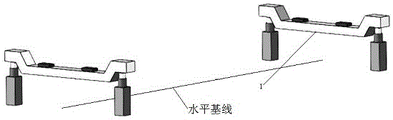
Fig. 1 is a schematic structural diagram of a beam mounting tool according to an embodiment of the present invention;
fig. 2 is a schematic structural diagram of a supporting unit of a beam mounting tool according to an embodiment of the present invention;
FIG. 3 is a schematic structural diagram of a state of supporting a box girder by a girder installation tool according to an embodiment of the present invention;
FIG. 4 is a schematic structural view of a girder transporting vehicle entering below a girder loading tool provided by an embodiment of the invention;
fig. 5 is a schematic partial structural view of a beam-mounting tool after removal of a carrying pole beam in the beam-mounting method according to the embodiment of the present invention;
fig. 6 is a schematic partial structure view of a girder transporting trolley after girder loading is completed in the girder loading method provided by the embodiment of the invention.
In the figure: 1. the supporting unit, 11, a jacking mechanism, 111, a piston type hydraulic cylinder, 112, a concrete buttress, 12, a shoulder pole beam, 13, a cushion pad block, 2, a box beam, 3, a beam transporting vehicle and 31, a pad pier.
Detailed Description
The invention is further illustrated with reference to the following figures and examples.
The structure, proportion, size and the like shown in the drawings are only used for matching with the content disclosed in the specification, so that the person skilled in the art can understand and read the description, and the description is not used for limiting the limit condition of the implementation of the invention, so the method has no technical essence, and any structural modification, proportion relation change or size adjustment still falls within the scope covered by the technical content disclosed by the invention without affecting the effect and the achievable purpose of the invention. In addition, the terms "upper", "lower", "left", "right", "middle" and "one" used in the present specification are for clarity of description, and are not intended to limit the scope of the present invention, and the relative relationship between the terms and the terms is not to be construed as a scope of the present invention.
The beam-mounting tool comprises a support unit 1 and a pad pier 31 as shown in figures 1-3; the supporting unit 1 comprises a carrying pole beam 12 and two jacking mechanisms 11; the carrying pole beam 12 has both ends in the longitudinal direction thereof, and the upper surface of the carrying pole beam 12 is in contact with the box girder 2; the two jacking mechanisms 11 are positioned at two ends of the carrying pole beam 12, arranged below the carrying pole beam 12 and vertical to the carrying pole beam 12; the distance between the side surfaces of the two jacking mechanisms 11 closest to each other is greater than the width of the trolley of the girder transporting vehicle 3; the number of the supporting units 1 is more than two, the supporting units 1 are distributed at intervals along the horizontal direction, the length direction of the shoulder pole beam 12 is vertical to the horizontal direction, and the end faces of one ends of the shoulder pole beams 12 of different supporting units 1 are positioned on the same plane; the pad pier 31 is arranged on a trolley of the beam transporting vehicle 3; when the pad pier 31 is arranged on the trolley of the girder transporting vehicle 3, the height of the top end of the pad pier 31 is greater than that of the part of the shoulder pole beam 12, which is in contact with the box girder 2; the jacking mechanism 11 drives the shoulder pole beam 12 to reciprocate up and down so as to realize the switching of the supporting unit 1 between the first state and the second state; in the first state, the maximum height of the bottom surface of the carrying pole beam 12 is larger than the maximum height of the trolley of the girder transporting trolley 3; in the second state, the minimum height of the upper surface of the shoulder pole 12 is smaller than the height of the upper surface of the pad pier 31 of the trolley located on the girder transporting vehicle 3. The heights each refer to a height from a mounting surface of the support unit 1, such as the ground.
The length of the carrying pole beam 12 should be larger than the sum of the width of the girder transporting vehicle 3 and the width of the jacking mechanisms 11, so that the space between the two jacking mechanisms 11 is enough for the girder transporting vehicle 3 to pass through. The width of the lifting mechanism 11 refers to the dimension of the lifting mechanism 11 along the length direction of the carrying pole beam 12 when the lifting mechanism 11 is arranged on the carrying pole beam 12.
The dimension of the carrying pole beam 12 in the longitudinal direction of the box girder 2 (the direction of the connecting line between the two support units 1) is defined as the width of the carrying pole beam 12. The dimension of the shoulder pole beam 12 in the height direction is defined as the thickness of the shoulder pole beam 12. The width of the carrying pole beam 12 and the thickness of the carrying pole beam 12 are calculated from the supporting force required for the box girder 2 to be supported. The calculation method is common knowledge of those skilled in the art and will not be described herein.
The upper surface of the shoulder pole beam 12 is used to contact the box girder 2, and therefore, the upper surface of the shoulder pole beam 12 may be a flat surface or a concave surface adapted to the shape of the bottom of the box girder 2. The lower surface of the shoulder pole beam 12 may be flat or convex to match the upper surface. Specifically, in one implementation, the carrying pole beam 12 has a concave structure; the concave structure comprises a groove part and two support connecting parts which are positioned at two sides of the groove and protrude upwards; the groove part is used for accommodating the box girder 2; the top ends of the two jacking mechanisms 11 are in one-to-one correspondence with the lower ends of the two supporting connecting parts and are detachably connected. The concave structure is adopted, which is not only beneficial to improving the bearing capacity of the carrying pole beam 12, but also can ensure that the box beam 2 is more stable when being placed at the upper part of the box beam, and meanwhile, when being beneficial to the later-stage beam loading, the beam transporting vehicle 3 is positioned.
The lifting mechanism 11 is used as a power system for lifting the shoulder pole beam 12, so that the structure can adopt various forms. Specifically, in one implementation, a hydraulic jacking buttress may be used as the jacking mechanism 11. More specifically, the hydraulic jacking buttress comprises a piston hydraulic cylinder 111 and a concrete buttress 112. The oil pipe of the hydraulic cylinder can be connected with the hydraulic system of the girder transporting vehicle 3 to obtain power. Each concrete buttress 112 can be cast in situ at a predetermined position, the hydraulic cylinders are installed after casting and curing are completed, and finally the shoulder pole beam 12 is placed on the corresponding hydraulic cylinder
Since the weight of the box girder 2 carried by the tool is large, a large power is required when the tool is lifted up. In order to prevent damage to the hydraulic system of the girder transporting vehicle 3, the present embodiment may further provide that the ram-type hydraulic cylinder 111 included in each group of the supporting units 1 is connected to the pump station through a synchronous control system. The pumping station provided independently supplies oil for the hydraulic cylinders, so that the forced damage to a hydraulic system of the carrier loader can be effectively prevented. Through the synchronous control system who improves, can be so that a plurality of pneumatic cylinders synchronization action, guarantee that 2 lifts of case roof beam are steady, avoid because the high nonconformity that individual pneumatic cylinder moved to causes local atress too big, take place the risk of empting. It is understood that the synchronous control system provided by the present embodiment may adopt any one of the systems in the prior art that can implement synchronous operation of a plurality of hydraulic cylinders.
In order to prevent the steel carrying pole beam 12 from damaging the box beam 2 when the box beam 2 is placed on the carrying pole beam 12, the embodiment may further provide that a plurality of cushion blocks 13 are arranged on the upper portion of the carrying pole beam 12, and the box beam 2 is located on the cushion blocks 13; at this time, the height of the pier 31 is larger than the sum of the heights of the cushion block 13 and the shoulder pole beam 12. The cushion blocks 13 can effectively prevent the stress damage of the box girder 2 by the carrying pole beam 12, and the increase of the height thereof does not affect the smooth removal of the carrying pole beam 12.
As shown in fig. 1, a horizontal base line is set along the ground, the supporting units 1 cross the horizontal base line, the length direction of the carrying pole beams 12 of the supporting units 1 is perpendicular to the horizontal base line, and the connecting line 1/2 of the lengths of the carrying pole beams 12 of the two groups of supporting units 1 is parallel to the horizontal base line or their vertical projection is coincident. The distance between the two groups of supporting units 1 should be smaller than the span of the first generation of beam transporting machine (single-beam single-door beam transporting machine), so as to meet the beam loading requirement of the first generation of beam transporting machine. In this condition, the distance between the two sets of support units 1 may be determined according to the length of the box girder 2. Due to the large weight of the box girder 2 itself, it is determined according to the general design requirements of the box girder 2 that the top girder point should remain within the end surface 3 m. In particular, in one implementation, the maximum distance between the top beam point between the spreader beam 12 and the box beam 2 and the end face of the box beam 2 is 3 meters.
The dress roof beam frock that this application embodiment provided, two sets of support element 1 can support case roof beam 2, fortune roof beam car 3 can be by getting into the below of case roof beam 2 between two climbing mechanism 11 of shoulder pole roof beam 12 below, can adjust the height of shoulder pole roof beam 12 through climbing mechanism 11, when fortune roof beam car 3 gets into, highly improves the assurance fortune roof beam car 3 of shoulder pole roof beam 12 and can get into (first state) smoothly. When the girder is loaded, the carrying pole beam 12 is lowered by the jacking mechanism 11, the box girder 2 is lowered to contact with the pad pier 31 of the trolley of the girder transporting vehicle 3, the carrying pole beam 12 is continuously lowered to separate the carrying pole beam 12 from the box girder 2 (second state), and then the carrying pole beam 12 is drawn out from the gap between the box girder 2 and the trolley of the girder transporting vehicle 3, so that the girder loading work can be completed. In practical applications, the number of the supporting units 1 may be determined according to the length of the box girder 2 and the number of supporting points required to be provided by the structure of the box girder 2 itself.
A beam mounting method adopting the beam mounting tool comprises the following steps:
the height of the carrying pole beam 12 is adjusted through the jacking mechanism 11, so that the height of the lower surface of the carrying pole beam 12 is higher than the maximum height of the trolley of the beam transporting trolley 3;
placing the box girder 2 on the carrying pole girder 12 by using a single-girder single-door type carrying girder machine;
the girder transporting vehicle 3 drives under the shoulder pole beam 12;
the height of the carrying pole beam 12 is reduced through the jacking mechanism 11, so that the box girder 2 is in contact with the upper surface of a pad pier 31 of a trolley of the girder transporting vehicle 3;
the height of the carrying pole beam 12 is further lowered to separate the carrying pole beam 12 from the box girder 2, and the carrying pole beam 12 is removed from below the box girder 2.
In the step of "placing the box girder 2 on the carrying pole girder 12 using the single-girder single-door type carrying girder machine", the end face of the box girder 2 is made parallel to the longitudinal direction of the carrying pole girder 12. The length direction of the box girder 2 is along the connecting line direction between the two supporting units 1.
In the step of "the girder transporting vehicle 3 is driven below the carrying pole beam 12", as shown in fig. 4, the girder transporting vehicle 3 is driven between the two jacking mechanisms 11 below the carrying pole beam 12, the length direction of the girder transporting vehicle 3 is consistent with the length direction of the box girder 2, the carrying pole beam 12 spans the girder transporting vehicle 3, and the two jacking mechanisms 11 of the same supporting unit 1 are located on both sides of the girder transporting vehicle 3.
After "removing carrying-pole beam 12 from under box girder 2", girder transporting vehicle 3 is driven away, and the loading of box girder 2 to the lower or ultra-lower position girder transporting vehicle by the single-girder single-door girder transporting machine is completed.
Although the embodiments of the present invention have been described with reference to the accompanying drawings, it is not intended to limit the scope of the present invention, and it should be understood by those skilled in the art that various modifications and variations can be made without inventive efforts by those skilled in the art based on the technical solutions of the present invention.