CN115110208A - Mesh crawler receiving device for non-woven melt-blown fabric production - Google Patents
Mesh crawler receiving device for non-woven melt-blown fabric production Download PDFInfo
- Publication number
- CN115110208A CN115110208A CN202211044502.5A CN202211044502A CN115110208A CN 115110208 A CN115110208 A CN 115110208A CN 202211044502 A CN202211044502 A CN 202211044502A CN 115110208 A CN115110208 A CN 115110208A
- Authority
- CN
- China
- Prior art keywords
- melt
- eccentric
- wall
- blown
- shell
- Prior art date
- Legal status (The legal status is an assumption and is not a legal conclusion. Google has not performed a legal analysis and makes no representation as to the accuracy of the status listed.)
- Granted
Links
- 239000004744 fabric Substances 0.000 title claims abstract description 35
- 238000004519 manufacturing process Methods 0.000 title claims description 12
- 230000005540 biological transmission Effects 0.000 claims abstract description 22
- 238000001816 cooling Methods 0.000 claims description 67
- XLYOFNOQVPJJNP-UHFFFAOYSA-N water Substances O XLYOFNOQVPJJNP-UHFFFAOYSA-N 0.000 claims description 31
- 230000006698 induction Effects 0.000 claims description 16
- 239000000463 material Substances 0.000 claims description 13
- 238000005096 rolling process Methods 0.000 claims 2
- 239000004020 conductor Substances 0.000 claims 1
- 238000004804 winding Methods 0.000 abstract description 7
- 238000009987 spinning Methods 0.000 description 8
- 239000000835 fiber Substances 0.000 description 7
- 238000004891 communication Methods 0.000 description 3
- 238000001914 filtration Methods 0.000 description 3
- 239000000155 melt Substances 0.000 description 3
- 238000010521 absorption reaction Methods 0.000 description 2
- 229920000642 polymer Polymers 0.000 description 2
- 239000004743 Polypropylene Substances 0.000 description 1
- 239000011358 absorbing material Substances 0.000 description 1
- 230000001153 anti-wrinkle effect Effects 0.000 description 1
- 230000009286 beneficial effect Effects 0.000 description 1
- 238000007664 blowing Methods 0.000 description 1
- 238000006243 chemical reaction Methods 0.000 description 1
- 230000007423 decrease Effects 0.000 description 1
- 238000009826 distribution Methods 0.000 description 1
- 230000000694 effects Effects 0.000 description 1
- 238000005516 engineering process Methods 0.000 description 1
- 230000017525 heat dissipation Effects 0.000 description 1
- 239000012535 impurity Substances 0.000 description 1
- 239000011810 insulating material Substances 0.000 description 1
- 238000009413 insulation Methods 0.000 description 1
- 239000007788 liquid Substances 0.000 description 1
- 238000002844 melting Methods 0.000 description 1
- 230000008018 melting Effects 0.000 description 1
- 239000007769 metal material Substances 0.000 description 1
- 238000000034 method Methods 0.000 description 1
- -1 polypropylene Polymers 0.000 description 1
- 229920001155 polypropylene Polymers 0.000 description 1
- 238000003825 pressing Methods 0.000 description 1
- 230000005855 radiation Effects 0.000 description 1
- 239000002994 raw material Substances 0.000 description 1
- 238000005057 refrigeration Methods 0.000 description 1
- 230000000630 rising effect Effects 0.000 description 1
Images




Classifications
-
- D—TEXTILES; PAPER
- D04—BRAIDING; LACE-MAKING; KNITTING; TRIMMINGS; NON-WOVEN FABRICS
- D04H—MAKING TEXTILE FABRICS, e.g. FROM FIBRES OR FILAMENTARY MATERIAL; FABRICS MADE BY SUCH PROCESSES OR APPARATUS, e.g. FELTS, NON-WOVEN FABRICS; COTTON-WOOL; WADDING ; NON-WOVEN FABRICS FROM STAPLE FIBRES, FILAMENTS OR YARNS, BONDED WITH AT LEAST ONE WEB-LIKE MATERIAL DURING THEIR CONSOLIDATION
- D04H1/00—Non-woven fabrics formed wholly or mainly of staple fibres or like relatively short fibres
- D04H1/40—Non-woven fabrics formed wholly or mainly of staple fibres or like relatively short fibres from fleeces or layers composed of fibres without existing or potential cohesive properties
- D04H1/54—Non-woven fabrics formed wholly or mainly of staple fibres or like relatively short fibres from fleeces or layers composed of fibres without existing or potential cohesive properties by welding together the fibres, e.g. by partially melting or dissolving
- D04H1/56—Non-woven fabrics formed wholly or mainly of staple fibres or like relatively short fibres from fleeces or layers composed of fibres without existing or potential cohesive properties by welding together the fibres, e.g. by partially melting or dissolving in association with fibre formation, e.g. immediately following extrusion of staple fibres
-
- D—TEXTILES; PAPER
- D01—NATURAL OR MAN-MADE THREADS OR FIBRES; SPINNING
- D01D—MECHANICAL METHODS OR APPARATUS IN THE MANUFACTURE OF ARTIFICIAL FILAMENTS, THREADS, FIBRES, BRISTLES OR RIBBONS
- D01D5/00—Formation of filaments, threads, or the like
- D01D5/08—Melt spinning methods
- D01D5/088—Cooling filaments, threads or the like, leaving the spinnerettes
-
- D—TEXTILES; PAPER
- D01—NATURAL OR MAN-MADE THREADS OR FIBRES; SPINNING
- D01D—MECHANICAL METHODS OR APPARATUS IN THE MANUFACTURE OF ARTIFICIAL FILAMENTS, THREADS, FIBRES, BRISTLES OR RIBBONS
- D01D5/00—Formation of filaments, threads, or the like
- D01D5/08—Melt spinning methods
- D01D5/098—Melt spinning methods with simultaneous stretching
- D01D5/0985—Melt spinning methods with simultaneous stretching by means of a flowing gas (e.g. melt-blowing)
-
- D—TEXTILES; PAPER
- D01—NATURAL OR MAN-MADE THREADS OR FIBRES; SPINNING
- D01D—MECHANICAL METHODS OR APPARATUS IN THE MANUFACTURE OF ARTIFICIAL FILAMENTS, THREADS, FIBRES, BRISTLES OR RIBBONS
- D01D7/00—Collecting the newly-spun products
-
- Y—GENERAL TAGGING OF NEW TECHNOLOGICAL DEVELOPMENTS; GENERAL TAGGING OF CROSS-SECTIONAL TECHNOLOGIES SPANNING OVER SEVERAL SECTIONS OF THE IPC; TECHNICAL SUBJECTS COVERED BY FORMER USPC CROSS-REFERENCE ART COLLECTIONS [XRACs] AND DIGESTS
- Y02—TECHNOLOGIES OR APPLICATIONS FOR MITIGATION OR ADAPTATION AGAINST CLIMATE CHANGE
- Y02P—CLIMATE CHANGE MITIGATION TECHNOLOGIES IN THE PRODUCTION OR PROCESSING OF GOODS
- Y02P70/00—Climate change mitigation technologies in the production process for final industrial or consumer products
- Y02P70/50—Manufacturing or production processes characterised by the final manufactured product
- Y02P70/62—Manufacturing or production processes characterised by the final manufactured product related technologies for production or treatment of textile or flexible materials or products thereof, including footwear
Landscapes
- Engineering & Computer Science (AREA)
- Textile Engineering (AREA)
- Mechanical Engineering (AREA)
- Nonwoven Fabrics (AREA)
- Curtains And Furnishings For Windows Or Doors (AREA)
Abstract
The invention discloses a mesh crawler belt receiving device for producing non-woven melt-blown fabric, which comprises a shell, wherein the front inner wall and the rear inner wall of the shell are rotatably connected with a pair of belt wheels, a mesh curtain belt is tensioned and sleeved on the pair of belt wheels, the upper end of the mesh curtain belt is used for receiving melt-blown fabric, a winding roller used for winding the melt-blown fabric is installed on the left side of the shell, a force transmission body is fixedly connected to the front inner wall and the rear inner wall of the shell and close to the right end of the inner side of the mesh curtain belt, a central cavity and two eccentric cavities are formed in the force transmission body, the two eccentric cavities are symmetrically distributed about the central cavity, and communicating grooves communicated with the eccentric cavities are symmetrically formed in the bottom of the inner wall of the central cavity. The invention utilizes Pascal principle to convert and increase the acting force generated by high-speed jet of the melt-blown die body to the mesh curtain belt, so that the melt-blown die body can be pulled, the stroke of the melt-blown die body is improved through the pulley block, the distance between the melt-blown die body and the mesh curtain belt is increased, and the influence of the undersize distance between the melt-blown die body and the mesh curtain belt on the product quality of melt-blown cloth is avoided.
Description
Technical Field
The invention relates to the technical field of melt-blown fabric production, in particular to a grid crawler receiving device for non-woven melt-blown fabric production.
Background
The melt-blown fabric is prepared by using polypropylene as a main raw material, firstly melting polymer slices, then filtering impurities in the melt, then conveying the melt to a spinning nozzle, then carrying out airflow drawing on the polymer melt extruded from the spinning nozzle by using high-speed hot air flow, blowing off the fiber to form superfine fiber, collecting the superfine fiber on a condensing screen curtain or a roller, and finally using a coiling machine to package the melt-blown fabric into rolls.
The fiber diameter of the melt-blown cloth can reach 0.5-10 microns, the voids are large, the structure is fluffy, the anti-wrinkle capacity is good, and the superfine fibers with unique capillary structures increase the number and the surface area of the fibers in unit area, so that the melt-blown cloth has good filtering property, shielding property, heat insulation property and oil absorption property, and can be used in the fields of air, liquid filtering materials, isolating materials, absorbing materials, mask materials, heat-insulating materials, oil absorption materials, wiping cloth and the like.
In order to improve the strength elongation in the actual production process, increase hot air flow or temperature is usually adopted, and the spinning speed of the melt is correspondingly increased, but the distance between the material receiving belt and the melt-blown die body is fixed, the original enough distance and time can not meet the requirement due to the change, the heat of the winding melt-blown cloth is gathered, the fineness and the fluffy degree of the spun fiber can be reduced, the distance between the material receiving belt and the melt-blown die body needs to be adjusted to adjust the blanking speed, and the manual adjustment mode is not accurate and rapid enough.
Therefore, we propose a mesh crawler receiving device for producing non-woven melt-blown fabric to solve the above problems.
Disclosure of Invention
The invention aims to provide a mesh crawler receiving device for producing non-woven melt-blown fabric to solve the problems in the background art.
In order to achieve the purpose, the invention adopts the following technical scheme:
a mesh crawler receiving device for non-woven melt-blown fabric production comprises a shell, wherein a pair of belt wheels are rotatably connected to the front inner wall and the rear inner wall of the shell, a mesh curtain belt is connected to the pair of belt wheels in a sleeved mode through tensioning of the belt wheels, the upper end of the mesh curtain belt is connected with the melt-blown fabric, a winding roller for winding the melt-blown fabric is installed on the left side of the shell, a force transfer body is fixedly connected to the inner side of the front inner wall and the rear inner wall of the shell and close to the right end of the mesh curtain belt, a central cavity and two eccentric cavities are formed in the force transfer body and symmetrically distributed about the central cavity, communicating grooves communicated with the eccentric cavities are symmetrically formed in the bottom of the inner wall of the central cavity, the central cavity and the eccentric cavities are respectively and vertically and hermetically slidably connected with a central piston and an eccentric piston, a piston rod is fixedly connected to the upper end of the central piston rod, a spring is sleeved outside the piston rod, and two ends of the spring are respectively propped against the central piston and the top end in the central cavity, the piston rod is connected with a sliding plate in a transmission way, the upper end of the sliding plate is rotatably connected with an induction wheel, the lower end of the sliding plate is inserted with a limiting rod in a sliding way, the shell is sequentially provided with a guide wheel and a pulley block above each eccentric cavity, the guide wheel is arranged at the front side of the net curtain belt, the inner top end of the shell is fixedly connected with a fixed plate, the guide wheel and the pulley block are rotatably arranged on one side of the fixed plate, the upper end of each eccentric piston is fixedly connected with a traction rope, the upper ends of the two traction ropes penetrate through the eccentric cavity, bypass the guide wheel and the pulley block and are then jointly and fixedly connected with a lifting plate, the lower end of the lifting plate is fixedly provided with a melt-blown die body, the inner top end of the shell is fixedly connected with a guide rod at a corresponding position of each eccentric cavity, and the guide rod is inserted in the lifting plate; the outer surface of the induction wheel is provided with a pressure induction area, the upper end of the force transmission body is provided with a sliding rheostat on the right side of the piston rod, the sliding rheostat comprises a resistance-changing rod fixedly mounted on the upper end of the force transmission body, the resistance-changing rod is connected with a sliding sheet in a sliding manner, the sliding sheet is fixedly connected with the piston rod, a plurality of cooling rollers are arranged in the shell at equal intervals and adopt a hollow structure, the cooling rollers are made of heat conduction materials, the outer surface of the cooling roller positioned on the rightmost side is provided with a contact area, the cooling rollers jointly rotate and are sleeved with two rotating plates, the same end of each two adjacent cooling rollers is communicated with a communication pipe, the cooling rollers positioned on two sides are connected with a water cooling system through pipelines, the water cooling system comprises a direct-current water pump, the direct-current water pump is electrically connected with a direct-current power supply through the sliding rheostat, and grooves are formed in the front inner wall and the rear wall of the shell, and two rotor plates rotate respectively and connect in the recess, right side fixed mounting has electric telescopic handle in the recess, electric telescopic handle's flexible end rotates and is connected with the lift wheel, and the lower extreme roll connection of lift wheel and rotor plate.
Preferably, the mesh curtain belt is made of elastic heat conduction materials.
Preferably, one side that the piston rod is relative with the slide is fixedly connected with right pinion rack and left pinion rack respectively, right pinion rack and the common meshing of left pinion rack have drive gear, drive gear rotates and is connected with the mounting panel, and mounting panel fixed connection is in the upper end of the biography power body.
Preferably, the cross section of the limiting rod is square.
Preferably, the lower end of the guide rod is fixedly connected with a limiting plate.
Preferably, the pressure sensing area is composed of a plurality of pressure sensors distributed in an annular array on the outer surface of the sensing wheel, and the contact area is composed of a plurality of contact sensors distributed in an annular array on the cooling roller.
Preferably, the inner top end of the eccentric cavity is longitudinally provided with a movable groove for the movement of the traction rope.
Preferably, the front and rear inner walls of the housing are provided with arc-shaped grooves for the movement of the cooling roller.
Compared with the prior art, the invention has the beneficial effects that:
1. the invention utilizes Pascal principle to convert and increase the acting force generated by high-speed jet of the melt-blown die body to the mesh curtain belt, so that the melt-blown die body can be pulled, the stroke of the melt-blown die body is improved through the pulley block, the distance between the melt-blown die body and the mesh curtain belt is increased, and the influence of the undersize distance between the melt-blown die body and the mesh curtain belt on the product quality of melt-blown cloth is avoided.
2. According to the invention, each cooling roller is arranged at the inner side of the upper end of the mesh curtain belt, the water cooling mode replaces an air cooling mode, burrs of melt-blown cloth caused by air cooling are avoided, and the cooling rollers are enabled not to influence the pressing of high-speed spinning on the induction wheel through the mutual matching of structures such as the induction area, the contact area and the electric telescopic rod, and are enabled to be in continuous contact with the mesh curtain belt after being stabilized, so that water cooling is kept;
and the sliding sheet slides on the resistance-changing rod by utilizing the descending of the induction wheel, so that the resistance of the slide rheostat is changed and reduced, the current in a circuit where the slide rheostat and the direct-current water pump are located is increased, the working efficiency of the direct-current water pump is improved, the flowing speed of a water body in each cooling roller is improved, and the cooling capacity is correspondingly improved.
Drawings
FIG. 1 is a front structural cross-sectional view of a mesh track receiving device for nonwoven meltblown fabric production in accordance with the present invention;
FIG. 2 is a partially enlarged schematic view of FIG. 1;
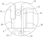
FIG. 3 is an enlarged schematic view of the structure at A in FIG. 2;
FIG. 4 is a schematic structural view of a side view of a junction between a pulley block and a melt-blown mold body of a mesh track receiving device for producing a non-woven melt-blown fabric according to the present invention;
FIG. 5 is a sectional view of a cooling roller of a mesh track receiving device for nonwoven meltblown web production according to the present invention from above;
FIG. 6 is a front sectional view of a cooling roller of a mesh crawler receiving device for nonwoven meltblown manufacture in accordance with the present invention.
In the figure: the device comprises a shell 1, a belt wheel 2, a curtain belt 3, a wind-up roll 4, a support plate 5, a force transfer body 6, a central cavity 7, an eccentric cavity 8, a communication groove 9, a central piston 10, an eccentric piston 11, a piston rod 12, a spring 13, a right toothed plate 14, a transmission gear 15, a sliding plate 16, a left toothed plate 17, a limiting rod 18, a sensing wheel 19, a traction rope 20, a guide wheel 21, a pulley block 22, a lifting plate 23, a guide rod 24, a melt-blown die body 25, a fixed plate 26, a limiting plate 27, a cooling roller 28, a communication pipe 29, an electric telescopic rod 30, a direct-flow water pump 31, a variable resistance rod 32, a sliding plate 33, a groove 34, a rotating plate 35 and a lifting wheel 36.
Detailed Description
The technical solutions in the embodiments of the present invention will be clearly and completely described below with reference to the drawings in the embodiments of the present invention, and it is obvious that the described embodiments are only a part of the embodiments of the present invention, and not all of the embodiments.
Referring to fig. 1-6, a mesh crawler receiving device for non-woven melt-blown fabric production comprises a shell 1, wherein a pair of belt pulleys 2 are rotatably connected to the front inner wall and the rear inner wall of the shell 1, a mesh curtain belt 3 is sleeved on the pair of belt pulleys 2 in a tensioning manner, the upper end of the mesh curtain belt 3 is connected with melt-blown fabric, a winding roller 4 for winding the melt-blown fabric is installed on the left side of the shell 1, and a lower melt-blown mold body 25 is provided. The structure of the existing melt-blown fabric material receiving structure is shown, and a motor for driving one belt wheel 2 is arranged outside the shell 1, so that the structure is irrelevant to the technical problem solved by the invention, and is not shown in the figure.
The overall thought of the invention is as follows:
firstly, the net curtain belt 3 is made of elastic heat conduction materials. The net curtain belt 3 has elasticity and heat conductivity, and can be specifically manufactured by modifying heat-resistant rubber and metal materials.
Secondly, on the basis of the first point, the upper end of the mesh curtain belt 3 is pressed down with certain strength by utilizing the spinning speed of the melt-blown die body 25, the position of the mesh curtain belt 3 corresponding to the melt-blown die body 25 can deform upwards or downwards to a certain degree and has certain acting force, so that the traction force of the melt-blown die body 25 is converted and increased, and the mesh curtain belt is suspended above the mesh curtain belt 3 and is in dynamic balance at the moment;
once melt the die body 25 and spout the increase of speed, high-speed spouting can produce bigger effort to the top of lace curtain area 3, and the deformation degree increases, with this effort conversion increase and make melt the die body 25 of spouting rise, the deformation degree of lace curtain area 3 here position reduces to improve and melt interval between die body 25 and the lace curtain area 3 of spouting, avoid because of spouting the too high fineness and fluffy degree decline that leads to of speed.
Thirdly, in the second point, the high-speed spinning of the melt-blown die body 25 means that the melt-blown fabric has a higher problem, the temperature is reduced by adopting a water cooling mode, an air cooling mode adopted in the traditional technology is replaced, and the problems that burrs are generated and increased due to induced air of the melt-blown fabric caused by air cooling are solved.
The following is a structural design made for the second point, specifically:
the front inner wall and the rear inner wall of the shell 1 are fixedly connected with a force transmission body 6 close to the right end on the inner side of the net curtain belt 3, a central cavity 7 and two eccentric cavities 8 are formed in the force transmission body 6, the two eccentric cavities 8 are symmetrically distributed about the central cavity 7, communicating grooves 9 communicated with the eccentric cavities 8 are symmetrically formed in the bottom of the inner wall of the central cavity 7, a central piston 10 and an eccentric piston 11 are hermetically and slidably connected in the vertical direction in the central cavity 7 and the eccentric cavities 8 respectively, the central piston 10, the eccentric piston 11, the communicating grooves 9, the central cavity 7 and the eccentric cavities 8 jointly form a sealed space, oil bodies are filled in the sealed space, and the central piston 10 increases acting force on the eccentric piston 11 through the oil bodies.
The upper end of the central piston 10 is fixedly connected with a piston rod 12, the upper end of the piston rod 12 penetrates through the central cavity 7, a spring 13 is sleeved outside the piston rod 12, and the two ends of the spring 13 are respectively propped against the central piston 10 and the top end in the central cavity 7, the elastic force of the spring 13 can maintain the melt-blown die body 25 to be suspended above the mesh curtain belt 3, the piston rod 12 is in transmission connection with a sliding plate 16, the opposite sides of the piston rod 12 and the sliding plate 16 are respectively and fixedly connected with a right toothed plate 14 and a left toothed plate 17, the right toothed plate 14 and the left toothed plate 17 are jointly meshed with a transmission gear 15, the left toothed plate 17, the transmission gear 15 and the right toothed plate 14 which are meshed with each other in sequence from left to right are arranged to convert the original downward force on the induction wheel 19 into the upward pulling force on the piston rod 12 and the central piston 10, then the downward pulling force on the eccentric piston 11 is converted, the transmission gear 15 is rotatably connected with a mounting plate, and the mounting plate is fixedly connected to the upper end of the force transmission body 6.
The upper end of the sliding plate 16 is rotatably connected with an induction wheel 19, the lower end of the sliding plate 16 is slidably inserted with a limiting rod 18, and the cross section of the limiting rod 18 is square, so that the sliding plate 16 can slide more stably.
The casing 1 is equipped with leading wheel 21 and assembly pulley 22 in proper order in the top in each eccentric chamber 8, and leading wheel 21 sets up the front side at net curtain area 3, can not influence the normal transmission in net curtain area 3, the interior top end fixedly connected with fixed plate 26 of casing 1, and leading wheel 21 and assembly pulley 22 all rotate and install the one side at fixed plate 26, the upper end fixedly connected with haulage rope 20 of each eccentric piston 11, the upper end of two haulage ropes 20 runs through eccentric chamber 8, walk around leading wheel 21 and assembly pulley 22, the common fixedly connected with lifter plate 23 in back, the lower extreme fixed mounting of lifter plate 23 has melt-blown die body 25, this is prior art, because haulage rope 20 is the tilt state at leading wheel 21 and eccentric piston 11, consequently vertically offer the movable groove that is used for haulage rope 20 activity at the interior top in eccentric chamber 8, avoid haulage rope 20 to receive the influence of frictional force.
The inner top end of the shell 1 is fixedly connected with a guide rod 24 at the corresponding position of each eccentric cavity 8, the guide rods 24 are inserted in the lifting plate 23, the guide rods 24 guide the sliding of the lifting plate 23 to enable the lifting plate to be stable, and the lower end of each guide rod 24 is fixedly connected with a limiting plate 27 to limit the descending of the lifting plate 23.
When the invention is in dynamic balance, the induction wheel 19 jacks up the mesh curtain belt 3, the melt-blown die body 25 is suspended above the mesh curtain belt 3, and the spring 13 is in a compressed state;
once the spinning speed of the melt-blown die body 25 is increased, the melt-blown die body is broken under the dynamic balance state, the mesh belt 3 drives the piston rod 12 and the central piston 10 to ascend through the transmission of the induction wheel 19, the sliding plate 16 and the toothed plate, a certain pressure is applied to one piston in the hydraulic system according to the pascal law, the same pressure increment must be generated on the other piston, if the area of the second piston is 10 times of that of the first piston, the force acting on the second piston is increased to 10 times of that of the first piston, and the pressures on the two pistons are equal. The area of the eccentric piston 11 in the invention is far larger than that of the central piston 10, so that the downward pulling force of the eccentric piston 11 can be increased through the arrangement, the melt-blown die body 25 can be pulled and pulled, and meanwhile, in order to improve the stroke of the melt-blown die body 25, the pulling rope 20 and the pulley block 22 are additionally arranged, but it needs to be noted that the pulling force is lost when the pulley block 22 is arranged, so that the number of the pulleys needs to be selectively arranged according to actual conditions, and the melt-blown die body 25 is pulled upwards.
The following is the structural design made by the third point, specifically:
the outer surface of the sensing wheel 19 is provided with a pressure sensing area, the pressure sensing area is composed of a plurality of pressure sensors distributed on the outer surface of the sensing wheel 19 in an annular array mode, the pressure sensors are in the prior art, and the annular array distribution is used for adapting to the sensing wheel 19 in a rotating environment.
The upper end of the force transmission body 6 and the right side of the piston rod 12 are provided with a slide rheostat, specifically, the slide rheostat comprises a resistance-changing rod 32 fixedly installed at the upper end of the force transmission body 6, a slide sheet 33 is connected on the resistance-changing rod 32 in a sliding manner, and the slide sheet 33 is fixedly connected with the piston rod 12; the upper end of the resistance-changing rod 32 and the sliding sheet 33 form a resistor in a circuit, and the required characteristics of rising of the sliding sheet 33 and reduction of the resistor are met.
A plurality of cooling rollers 28 are arranged in the shell 1 at equal intervals, the cooling rollers 28 are of hollow structures, the cooling rollers 28 are made of heat conduction materials, and heat exchange is carried out to the maximum extent.
The outer surface of the cooling roller 28 located furthest to the right is provided with a contact zone which is formed by a plurality of contact sensors distributed in an annular array on the cooling roller 28, the contact sensors being of the prior art and being designed to accommodate the cooling roller 28 in a rotating environment.
Two rotating plates 35 are sleeved on the plurality of cooling rollers 28 in a rotating mode, arc-shaped grooves used for movement of the cooling rollers 28 are formed in the front inner wall and the rear inner wall of the shell 1, and moving space of the cooling rollers 28 in the rotating process is provided.
The same end of every two adjacent cooling rollers 28 is communicated with a communicating pipe 29, the communicating pipe 29 is a hard pipe and is in sealed rotary connection with the cooling rollers 28, normal rotation of the cooling rollers 28 cannot be influenced, the cooling rollers 28 on two sides are connected with a water cooling system through pipelines, the water cooling system comprises a direct current water pump 31, the direct current water pump 31 is electrically connected with a direct current power supply through a sliding rheostat, the water cooling system is a common water cooling system in the prior art and comprises a water tank, a refrigeration element and the like, and a circulation loop is formed between the water cooling system and the cooling rollers 28.
The inner wall is seted up flutedly 34 around casing 1, and two rotor plates 35 elasticity respectively rotates to be connected in recess 34, and right side fixed mounting has electric telescopic handle 30 in the recess 34, and electric telescopic handle 30's flexible end rotates and is connected with lifting wheel 36, and lifting wheel 36 and rotor plate 35's lower extreme roll connection upwards promotes lifting wheel 36 through electric telescopic handle 30 and rotates in order to drive rotor plate 35.
In the invention, each cooling roller 28 under dynamic balance is contacted with the inner side of the upper end of the mesh curtain belt 3, heat in the melt-blown cloth is transferred to the cooling roller 28 through contact and radiation, the cooling roller 28 rotates along with the transmission of the mesh curtain belt 3, instead of an air cooling mode, it needs to be explained here that one end of the cooling roller 28 far away from the melt-blown die body 25 and positioned at the leftmost side is a water inlet end, one end of the cooling roller 28 close to the melt-blown die body 25 and positioned at the rightmost side is a water outlet end, so that the temperature of a water body from right to left is gradually reduced, compared with a mode that the temperature of the water body from right to left is gradually increased, the heat dissipation is more uniform, the condition that the temperature difference with the melt-blown cloth is too large and the subsequent temperature difference is too small through a water cooling mode is avoided, and the production quality of the melt-blown cloth is improved.
Once the spinning speed of the melt-blown die body 25 is increased and the pressure sensed by the sensing area on the outer surface of the sensing wheel 19 is increased, the sensing area on the outer surface of the sensing wheel 19 senses and converts the pressure into an electric signal to be sent to the controller, wherein the controller is in the prior art, and is electrically connected with the sensing area, the contact area and the electric telescopic rod 30;
the controller controls the electric telescopic rod 30 to descend, so that the rotating plate 35 and the cooling roller 28 descend to a position where the rotating plate and the cooling roller are not in contact with the mesh curtain belt 3, resistance to the downward pressure of the induction wheel 19 is avoided, once the pressure sensed by the induction wheel 19 is constant, the electric telescopic rod 30 pushes the lifting wheel 36 upwards, and as the mesh curtain belt 3 is inclined on two sides of the induction wheel 19, the plurality of cooling rollers 28 are arranged on the same rotating plate 35, so that the right end of the rotating plate 35 is driven to ascend, and the electric telescopic rod 30 stops moving until the contact area of the outer surface of the cooling roller 28 on the rightmost side is contacted.
Meanwhile, the piston rod 12 drives the sliding sheet 33 to slide upwards on the rheostat 32 so as to reduce the resistance of the slide rheostat, increase the current in a circuit where the slide rheostat and the direct current water pump 31 are located, improve the working efficiency of the direct current water pump 31, improve the flowing speed of the water body in each cooling roller 28 and correspondingly improve the cooling capacity.
The above description is only for the preferred embodiment of the present invention, but the scope of the present invention is not limited thereto, and any person skilled in the art should be considered to be within the technical scope of the present invention, and the technical solutions and the inventive concepts thereof according to the present invention should be equivalent or changed within the scope of the present invention.
Claims (8)
1. The utility model provides a net track receiving arrangement is used in production of non-woven melt-blown fabric, includes casing (1), the inner wall rotates around casing (1) and is connected with a pair of band pulley (2), and is a pair of band pulley (2) tensioning has cup jointed net curtain area (3), the upper end of net curtain area (3) connects the material melt-blown fabric, wind-up roll (4) that are used for the rolling melt-blown fabric are installed in the left side of casing (1), its characterized in that: the front inner wall and the rear inner wall of the shell (1) are fixedly connected with a force transfer body (6) close to the right side on the inner side of the mesh belt (3), a central cavity (7) and two eccentric cavities (8) are arranged in the force transfer body (6), the two eccentric cavities (8) are symmetrically distributed about the central cavity (7), communicating grooves (9) communicated with the eccentric cavities (8) are symmetrically formed in the bottom of the inner wall of the central cavity (7), the central cavity (7) and the eccentric cavities (8) are respectively connected with a central piston (10) and an eccentric piston (11) in a gas-tight sliding mode in the vertical direction, the upper end of the central piston (10) is fixedly connected with a piston rod (12), the upper end of the piston rod (12) penetrates through the central cavity (7), a spring (13) is sleeved outside the piston rod (12), and two ends of the spring (13) respectively abut against the top ends of the central piston (10) and the inner end of the central cavity (7), the device is characterized in that a sliding plate (16) is connected to the piston rod (12) in a transmission manner, an induction wheel (19) is rotatably connected to the upper end of the sliding plate (16), a limiting rod (18) is inserted into the lower end of the sliding plate (16) in a sliding manner, a guide wheel (21) and a pulley block (22) are sequentially arranged above each eccentric cavity (8) of the shell (1), the guide wheel (21) is arranged on the front side of the mesh curtain belt (3), a fixing plate (26) is fixedly connected to the inner top end of the shell (1), the guide wheel (21) and the pulley block (22) are rotatably arranged on one side of the fixing plate (26), the upper end of each eccentric piston (11) is fixedly connected with a traction rope (20), the upper ends of the two traction ropes (20) penetrate through the eccentric cavities (8), bypass the guide wheel (21) and the pulley block (22) and are fixedly connected with a lifting plate (23) together after the guide wheel (21) and the pulley block (22), and the lower end of the lifting plate (23) is fixedly installed with a melt-blown mold body (25), a guide rod (24) is fixedly connected to the inner top end of the shell (1) and the corresponding position of each eccentric cavity (8), and the guide rod (24) is inserted into the lifting plate (23);
the outer surface of the induction wheel (19) is provided with a pressure induction area, the upper end of the force transmission body (6) is provided with a sliding rheostat on the right side of the piston rod (12), the sliding rheostat comprises a resistance changing rod (32) fixedly mounted on the upper end of the force transmission body (6), a sliding sheet (33) is connected on the resistance changing rod (32) in a sliding mode, the sliding sheet (33) is fixedly connected with the piston rod (12), the shell (1) is internally provided with a plurality of cooling rollers (28) at equal intervals, the cooling rollers (28) are of a hollow structure, the cooling rollers (28) are made of heat conducting materials, the outer surface of the cooling roller (28) located on the rightmost side is provided with a contact area, the cooling rollers (28) are jointly rotatably sleeved with two rotating plates (35), the same end of every two adjacent cooling rollers (28) is communicated with a communicating pipe (29), and the cooling rollers (28) located on two sides are connected with a water cooling system through pipelines, the water cooling system comprises a direct-current water pump (31), the direct-current water pump (31) is electrically connected with a direct-current power supply through a sliding rheostat, a groove (34) is formed in the front inner wall and the rear inner wall of the shell (1), two rotating plates (35) are respectively connected in the groove (34) in a rotating mode, an electric telescopic rod (30) is fixedly installed on the inner right side of the groove (34), the telescopic end of the electric telescopic rod (30) is connected with a lifting wheel (36) in a rotating mode, and the lifting wheel (36) is connected with the lower end of the rotating plates (35) in a rolling mode.
2. The apparatus of claim 1, wherein the endless track comprises: the net curtain belt (3) is made of elastic heat conduction materials.
3. The apparatus of claim 1, wherein the endless track comprises: piston rod (12) and slide (16) relative one side respectively fixedly connected with right pinion rack (14) and left pinion rack (17), right pinion rack (14) and left pinion rack (17) mesh jointly have drive gear (15), drive gear (15) rotate and are connected with the mounting panel, and mounting panel fixed connection is in the upper end of power transmission body (6).
4. The apparatus of claim 1, wherein the mesh caterpillar receiving apparatus comprises: the cross section of the limiting rod (18) is square.
5. The apparatus of claim 1, wherein the endless track comprises: the lower end of the guide rod (24) is fixedly connected with a limiting plate (27).
6. The apparatus of claim 1, wherein the endless track comprises: the pressure sensing zone consists of a plurality of pressure sensors distributed in an annular array on the outer surface of the sensing wheel (19), and the contact zone consists of a plurality of contact sensors distributed in an annular array on the cooling roller (28).
7. The apparatus of claim 1, wherein the endless track comprises: the inner top end of the eccentric cavity (8) is longitudinally provided with a movable groove for the movement of the traction rope (20).
8. The apparatus of claim 1, wherein the endless track comprises: the front inner wall and the rear inner wall of the shell (1) are provided with arc-shaped grooves for the movement of the cooling roller (28).
Priority Applications (1)
| Application Number | Priority Date | Filing Date | Title |
|---|---|---|---|
| CN202211044502.5A CN115110208B (en) | 2022-08-30 | 2022-08-30 | Grid crawler receiving device for nonwoven melt-blown fabric production |
Applications Claiming Priority (1)
| Application Number | Priority Date | Filing Date | Title |
|---|---|---|---|
| CN202211044502.5A CN115110208B (en) | 2022-08-30 | 2022-08-30 | Grid crawler receiving device for nonwoven melt-blown fabric production |
Publications (2)
| Publication Number | Publication Date |
|---|---|
| CN115110208A true CN115110208A (en) | 2022-09-27 |
| CN115110208B CN115110208B (en) | 2023-08-15 |
Family
ID=83335765
Family Applications (1)
| Application Number | Title | Priority Date | Filing Date |
|---|---|---|---|
| CN202211044502.5A Active CN115110208B (en) | 2022-08-30 | 2022-08-30 | Grid crawler receiving device for nonwoven melt-blown fabric production |
Country Status (1)
| Country | Link |
|---|---|
| CN (1) | CN115110208B (en) |
Citations (10)
| Publication number | Priority date | Publication date | Assignee | Title |
|---|---|---|---|---|
| CN110586369A (en) * | 2019-10-17 | 2019-12-20 | 长沙佐迩信息科技有限公司 | Environmental protection dust device is with firm support frame |
| CN110846812A (en) * | 2019-11-14 | 2020-02-28 | 浙江铭诚机械设备有限公司 | An online rotating platform equipment used in polymer extrusion into web |
| CN111408312A (en) * | 2020-05-18 | 2020-07-14 | 胡军亮 | Kneading machine with cylinder cover automatic opening and closing function |
| CN211420620U (en) * | 2019-12-04 | 2020-09-04 | 山东万得集团有限公司 | Temperature-controlled calender |
| CN112011895A (en) * | 2020-09-04 | 2020-12-01 | 嘉兴学院 | Cooling receiving device for melt-blown non-woven fabric on-line production |
| CN112251823A (en) * | 2020-10-14 | 2021-01-22 | 广州坤立服装有限公司 | A kind of melt-blown cloth production equipment with adjustable spinning speed |
| CN212505306U (en) * | 2020-06-02 | 2021-02-09 | 无锡爱杰美思机械有限公司 | Mesh crawler receiving device for non-woven melt-blown fabric production |
| CN214060853U (en) * | 2020-12-22 | 2021-08-27 | 常州优创机械科技有限公司 | Net forming device for melt-blowing equipment |
| CN113403701A (en) * | 2021-08-17 | 2021-09-17 | 江苏柏琳家用纺织品有限公司 | Melt blown fiber production mechanism |
| CN113529314A (en) * | 2021-07-02 | 2021-10-22 | 济南讷兹纺织材料有限公司 | Warp beam sizing equipment capable of improving yarn sizing permeability |
-
2022
- 2022-08-30 CN CN202211044502.5A patent/CN115110208B/en active Active
Patent Citations (10)
| Publication number | Priority date | Publication date | Assignee | Title |
|---|---|---|---|---|
| CN110586369A (en) * | 2019-10-17 | 2019-12-20 | 长沙佐迩信息科技有限公司 | Environmental protection dust device is with firm support frame |
| CN110846812A (en) * | 2019-11-14 | 2020-02-28 | 浙江铭诚机械设备有限公司 | An online rotating platform equipment used in polymer extrusion into web |
| CN211420620U (en) * | 2019-12-04 | 2020-09-04 | 山东万得集团有限公司 | Temperature-controlled calender |
| CN111408312A (en) * | 2020-05-18 | 2020-07-14 | 胡军亮 | Kneading machine with cylinder cover automatic opening and closing function |
| CN212505306U (en) * | 2020-06-02 | 2021-02-09 | 无锡爱杰美思机械有限公司 | Mesh crawler receiving device for non-woven melt-blown fabric production |
| CN112011895A (en) * | 2020-09-04 | 2020-12-01 | 嘉兴学院 | Cooling receiving device for melt-blown non-woven fabric on-line production |
| CN112251823A (en) * | 2020-10-14 | 2021-01-22 | 广州坤立服装有限公司 | A kind of melt-blown cloth production equipment with adjustable spinning speed |
| CN214060853U (en) * | 2020-12-22 | 2021-08-27 | 常州优创机械科技有限公司 | Net forming device for melt-blowing equipment |
| CN113529314A (en) * | 2021-07-02 | 2021-10-22 | 济南讷兹纺织材料有限公司 | Warp beam sizing equipment capable of improving yarn sizing permeability |
| CN113403701A (en) * | 2021-08-17 | 2021-09-17 | 江苏柏琳家用纺织品有限公司 | Melt blown fiber production mechanism |
Also Published As
| Publication number | Publication date |
|---|---|
| CN115110208B (en) | 2023-08-15 |
Similar Documents
| Publication | Publication Date | Title |
|---|---|---|
| CN212640791U (en) | Angle-adjustable melt-blown fabric receiving device | |
| CN112251823B (en) | Melt-blown fabric production equipment capable of adjusting spinning speed | |
| CN115110208B (en) | Grid crawler receiving device for nonwoven melt-blown fabric production | |
| CN111962208A (en) | Production process of melt-blown fabric | |
| CN212687223U (en) | Improved yarn guide equipment for polyester fibers | |
| CN113770184A (en) | Stretching device for producing welding wires | |
| CN117535876A (en) | Special hot rolling mill of non-woven fabric production | |
| CN109162057B (en) | Non-woven fabric cooling device capable of achieving uniform cooling | |
| CN207325624U (en) | A kind of efficient Copper fabrication extruder | |
| CN222287799U (en) | Cooling device is used in glass fiber mat production | |
| CN218478899U (en) | Anti-oxidation dyed yarn dyeing device with copper nano-particles added | |
| CN217785899U (en) | Heat exchanger capable of adjusting liquid level of cooling liquid to rise and fall according to temperature change | |
| CN217479765U (en) | Constant temperature setting equipment is used in knitted fabric production and processing | |
| CN222613755U (en) | Flattening device is used in warp knitting surface fabric processing | |
| CN211082661U (en) | Pressure-adjustable gas spring, lifting device and lifting table | |
| CN114262984A (en) | Intelligent intermittent receiving device for melt-blown fabric production | |
| CN208501336U (en) | A kind of clothes processing fabric ironing machine | |
| CN217005027U (en) | Cooling device is used in steel wire production | |
| CN211420620U (en) | Temperature-controlled calender | |
| CN113638253A (en) | Processing equipment for steel wire rope rigging | |
| CN217376625U (en) | Automatic winding device for melt-blown fabric electret | |
| CN116971129B (en) | A new type of polyester webbing production equipment and process with light-sensitive color change | |
| CN111254585A (en) | Pre-reinforcing method after non-woven fabric web formation | |
| CN222948647U (en) | Fabric shaping and drying equipment | |
| CN217555389U (en) | Cloth storage device for abrasive cloth production line |
Legal Events
| Date | Code | Title | Description |
|---|---|---|---|
| PB01 | Publication | ||
| PB01 | Publication | ||
| SE01 | Entry into force of request for substantive examination | ||
| SE01 | Entry into force of request for substantive examination | ||
| GR01 | Patent grant | ||
| GR01 | Patent grant |