CN115090969A - Clamping device is used in threaded rod processing - Google Patents
Clamping device is used in threaded rod processing Download PDFInfo
- Publication number
- CN115090969A CN115090969A CN202211019829.7A CN202211019829A CN115090969A CN 115090969 A CN115090969 A CN 115090969A CN 202211019829 A CN202211019829 A CN 202211019829A CN 115090969 A CN115090969 A CN 115090969A
- Authority
- CN
- China
- Prior art keywords
- plate
- shaped
- fixed
- threaded rod
- processing
- Prior art date
- Legal status (The legal status is an assumption and is not a legal conclusion. Google has not performed a legal analysis and makes no representation as to the accuracy of the status listed.)
- Withdrawn
Links
Images




Classifications
-
- B—PERFORMING OPERATIONS; TRANSPORTING
- B23—MACHINE TOOLS; METAL-WORKING NOT OTHERWISE PROVIDED FOR
- B23G—THREAD CUTTING; WORKING OF SCREWS, BOLT HEADS, OR NUTS, IN CONJUNCTION THEREWITH
- B23G1/00—Thread cutting; Automatic machines specially designed therefor
- B23G1/44—Equipment or accessories specially designed for machines or devices for thread cutting
-
- B—PERFORMING OPERATIONS; TRANSPORTING
- B23—MACHINE TOOLS; METAL-WORKING NOT OTHERWISE PROVIDED FOR
- B23Q—DETAILS, COMPONENTS, OR ACCESSORIES FOR MACHINE TOOLS, e.g. ARRANGEMENTS FOR COPYING OR CONTROLLING; MACHINE TOOLS IN GENERAL CHARACTERISED BY THE CONSTRUCTION OF PARTICULAR DETAILS OR COMPONENTS; COMBINATIONS OR ASSOCIATIONS OF METAL-WORKING MACHINES, NOT DIRECTED TO A PARTICULAR RESULT
- B23Q11/00—Accessories fitted to machine tools for keeping tools or parts of the machine in good working condition or for cooling work; Safety devices specially combined with or arranged in, or specially adapted for use in connection with, machine tools
- B23Q11/10—Arrangements for cooling or lubricating tools or work
-
- B—PERFORMING OPERATIONS; TRANSPORTING
- B23—MACHINE TOOLS; METAL-WORKING NOT OTHERWISE PROVIDED FOR
- B23Q—DETAILS, COMPONENTS, OR ACCESSORIES FOR MACHINE TOOLS, e.g. ARRANGEMENTS FOR COPYING OR CONTROLLING; MACHINE TOOLS IN GENERAL CHARACTERISED BY THE CONSTRUCTION OF PARTICULAR DETAILS OR COMPONENTS; COMBINATIONS OR ASSOCIATIONS OF METAL-WORKING MACHINES, NOT DIRECTED TO A PARTICULAR RESULT
- B23Q3/00—Devices holding, supporting, or positioning work or tools, of a kind normally removable from the machine
Landscapes
- Engineering & Computer Science (AREA)
- Mechanical Engineering (AREA)
- Jigs For Machine Tools (AREA)
Abstract
The invention discloses a clamping device for processing a threaded rod, and relates to the technical field of threaded rod processing. The clamping device for machining the threaded rod comprises a machine tool and a workpiece, wherein a three-jaw chuck for clamping and fixing the workpiece is arranged in the machine tool, a mechanical arm is arranged in the machine tool, a cutter bar is installed on the mechanical arm, and a blade for cutting the thread of the workpiece is arranged on the cutter bar. This kind of clamping device is used in threaded rod processing, through the transmission, make the clearance pole slide on the screw thread surface after the cutting, at gliding in-process, impetus and the rotation effect of clearance pole self through coupling spring, the realization is to flank of tooth and tooth root position on the screw thread rotatory clearance, clearance effect through the clearance pole, avoid the work piece to be fixed and the in-process of cutting because of row material unsmooth production that causes the root of tooth position on the screw thread to cut the tumour at the centre gripping, the processingquality of screw thread on the threaded rod has been improved, the centre gripping subassembly of being convenient for is used the centre gripping processing of threaded rod.
Description
Technical Field
The invention relates to the technical field of threaded rod processing, in particular to a clamping device for processing a threaded rod.
Background
The threaded rod, also called screw rod, is a cylinder with a spiral groove cut on the outer surface or a cone with a conical spiral groove cut on the outer surface. The screw rods have different heads, namely an outer hexagonal screw rod, a large flat screw rod, an inner hexagonal screw rod and the like, and the screw rods work under the conditions of high temperature, certain corrosion, strong abrasion and large torque, so the screw rods are high-temperature resistant and do not deform at high temperature; wear resistance and long service life; corrosion resistance, and the material has corrosiveness; the strength is high, and the high-speed high-torque high-speed motor can bear large torque; the cutting machining performance is good; small residual stress after heat treatment, small thermal deformation and the like.
In the process of processing the thread of the threaded rod, a forming cutter or a grinding tool is generally used for processing the thread on a workpiece, and mainly comprises turning, milling, tapping, threading, grinding, whirlwind cutting and the like.
The mode through the turning carries out the in-process of processing to the screw thread of threaded rod, carries out the centre gripping through the centre gripping subassembly to the threaded rod and fixes, but at the fixed back of centre gripping, thread cutting adds man-hour, often can arrange the material not smooth because of the tooth root position of screw, causes the screw thread tooth root position to produce the long-pending tumour of cutting, and can't discharge the clearance to the long-pending tumour that the tooth root position produced on the current centre gripping subassembly, the processingquality of screw thread on the reduction threaded rod, the centre gripping subassembly of being not convenient for is used the centre gripping processing of threaded rod.
Disclosure of Invention
The invention aims to provide a clamping device for processing a threaded rod, which aims to solve the problems in the background technology.
In order to achieve the purpose, the invention provides the following technical scheme: a clamping device for processing a threaded rod comprises a machine tool and a workpiece, wherein a three-jaw chuck for clamping and fixing the workpiece is arranged in the machine tool, a manipulator is arranged in the machine tool, a cutter bar is arranged on the manipulator, a blade for cutting the thread of the workpiece is arranged on the cutter bar, the machine tool is provided with a clamping component for clamping and supporting a workpiece in the cutting process, a first mounting plate and a second mounting plate are arranged in the machine tool, the first mounting plate and the second mounting plate are respectively positioned at two sides of the cutter bar, a first pushing assembly and a second pushing assembly which are respectively used for pushing the first mounting plate and the second mounting plate are arranged inside the machine tool, be provided with on the first mounting panel and be used for the refrigerated cooling subassembly of cooling down of cutting in-process, be fixed with the L template on the second mounting panel, be provided with the clearance subassembly that is used for work piece cutting back thread groove to clear up on the L template.
Preferably, clamping component is including setting up two bar plates in the lathe inside, two backup pads are fixed to the relative one side symmetry of bar plate, two relatively the one end of backup pad is fixed with the arc grip block, the arc grip block is provided with a plurality of balls with the relative centre gripping of work piece one side, the inside of lathe is provided with the direction subassembly that is used for two bar plate driven drive assembly and direction among the drive process.
Preferably, the driving assembly comprises two first fixing plates fixed inside the machine tool, the two strip-shaped plates are located between the two first fixing plates, the two first fixing plates are rotatably connected with a double-headed screw, threads at two ends of the double-headed screw are arranged in opposite rotating directions, the two strip-shaped plates are respectively meshed with two ends of the double-headed screw, and a rotating wheel is fixed at one end of the double-headed screw;
the direction subassembly is including seting up the guiding hole on two strip shaped plates, and sliding connection has the guide bar on two relative guiding holes, the both ends of guide bar are fixed respectively on two first fixed plates.
Preferably, the first pushing assembly comprises a first connecting plate fixed on one side of the arc-shaped clamping plate, the first connecting plate is connected with a plurality of first T-shaped rods in a sliding manner, one end of each first T-shaped rod is fixed with the first mounting plate, a first spring is sleeved on the side wall of each first T-shaped rod, and the first mounting plate is abutted against one side of the cutter bar under the elastic force of each first spring;
the cooling assembly comprises a blower installed on the first installation plate, an air inlet pipe and an air outlet pipe are installed at the air inlet end and the air outlet end of the blower respectively, and the air outlet pipe is arranged by leaning on a workpiece.
Preferably, the second promotes the subassembly including fixing the second connecting plate on the arc grip block of opposite side, sliding connection has a plurality of second T type poles on the second connecting plate, each the one end and the second mounting panel of second T type pole are fixed mutually, each the cover is equipped with the second spring on the lateral wall of second T type pole, the second mounting panel offsets with the opposite side of cutter arbor and sets up under the spring action of second spring.
Preferably, the clearance subassembly is including fixing the shape board that returns at the L template, the upper end of L template is connected with the U template through coupling assembling, it is connected with the dwang to rotate on the U template, install on the U template and be used for dwang driven driving motor, the dwang is located back the shape board, the installation cavity has been seted up to the one end of dwang, there is the clearance pole inside of installation cavity through connecting spring coupling, clearance pole sliding connection is on the installation cavity, be provided with the extrusion subassembly that is used for U template extrusion to promote on the L template.
Preferably, coupling assembling is including fixing a plurality of sleeves on the L template, each sheathed tube inside is connected with the connecting rod through connecting spring, each the other end of connecting rod is fixed mutually with the lower extreme of U template.
Preferably, the extrusion subassembly is including setting up the rectangular plate in L template top, be provided with the sliding assembly who is used for the rectangular plate motion direction on the L template, one side of rectangular plate is fixed with L type driving plate, one side that rectangular plate and U template are relative is fixed with operation panel and push pedal respectively, the inclined plane has been seted up on the operation panel, offset the setting between push pedal and the inclined plane, be provided with on the dwang and be used for the driven transmission assembly of L type driving plate.
Preferably, a plurality of even boards, each that transmission assembly fixes on the dwang lateral wall even rotate respectively on the board and be connected with the sleeve, each sliding connection has the promotion round pin that is used for L type driving plate to promote on the sleeve, each telescopic internal connection has the third spring, the other end of third spring is fixed mutually with the one end that promotes the round pin.
Preferably, the sliding assembly comprises a plurality of square plates fixed on the L-shaped plate, the square plates are respectively connected with T-shaped guide rods in a sliding mode, one end of each T-shaped guide rod is fixed to the corresponding rectangular plate, and a fourth spring is sleeved on the side wall of each T-shaped guide rod.
Compared with the prior art, the invention has the beneficial effects that:
(1) this kind of clamping device is used in threaded rod processing through clamping component, makes two bar plate atresss carry out the motion of being close to each other, and at the in-process that two bar plate atress were close to the motion each other, makes the arc grip block in each backup pad offset with the both sides of work piece respectively on two bar plates, carries out the centre gripping to the work piece and supports, avoids the work piece to cause the in-process of cutting to take place the shake because of work piece self length overlength in the car of crossing of cutting process, has improved the thread machining quality of threaded rod.
(2) This kind of clamping device is used in threaded rod processing, first mounting panel carries out the in-process that removes along with the removal of cutter arbor in step, start the hair-dryer on the first mounting panel, in-process at the hair-dryer start, inhale the inside of hair-dryer and blow away through the work piece of outlet duct orientation cutting in-process through the intake pipe with the air of outside, the air that blows off on the outlet duct cools off the temperature to the work piece in the cutting process and the blade on the cutter arbor, reduce the high temperature that produces in the cutting process and accelerate the wearing and tearing of blade on the cutter arbor, and the cooling effect of giving vent to anger through the outlet duct, reduce the temperature of work piece cutting processing rear surface, the taking of the work piece of being convenient for is unloaded.
(3) The clamping device for processing the threaded rod drives the L-shaped plate to synchronously move in the process that the second mounting plate synchronously moves along with the movement of the cutter bar, the driving motor is started in the process that the L-shaped plate moves, the rotating rod and the cleaning rod are driven to rotate by the driving motor, one end of the cleaning rod is abutted against the surface of the cut thread and rotates under the driving of the driving motor in the rotating process of the rotating rod, the second mounting plate and the L-shaped plate are driven to synchronously move by the cutter bar and rotate in the cutting process of a workpiece in the process that the cleaning rod is abutted against the surface of the cut thread, the cleaning rod slides on the surface of the cut thread, and the upper tooth surface and the tooth root part of the thread are rotatably cleaned by the pushing action of the connecting spring and the rotating action of the cleaning rod in the sliding process, through the cleaning action of clearance pole, avoid the work piece at the fixed and cutting in-process of centre gripping because of arrange material not smooth lead to the fact the production of tooth root position volume cutting tumour on the screw thread, improved the processingquality of screw thread on the threaded rod, the centre gripping subassembly of being convenient for is used the centre gripping processing of threaded rod.
Drawings
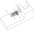
FIG. 1 is a schematic view of the overall configuration of the present invention;
FIG. 2 is a schematic view of the internal structure of the machine tool of the present invention;
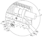
FIG. 3 is a schematic view of a clamping assembly of the present invention;
FIG. 4 is a schematic structural view of a first pushing assembly and a second pushing assembly of the present invention;
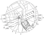
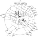
FIG. 5 is a schematic view of the cleaning assembly and the pressing assembly of the present invention;
FIG. 6 is an enlarged view of the structure at A in FIG. 3
FIG. 7 is an enlarged view of the structure at B in FIG. 4
FIG. 8 is an enlarged view of the structure at C in FIG. 4
Fig. 9 is an enlarged schematic view of the structure at D in fig. 5.
In the figure: 1. a machine tool; 2. a workpiece; 3. a three-jaw chuck; 4. a manipulator; 5. a cutter bar; 6. a clamping assembly; 601. a strip-shaped plate; 602. a support plate; 603. an arc-shaped clamping plate; 7. a drive assembly; 701. a first fixing plate; 702. a double-ended screw; 703. a rotating wheel; 8. a guide assembly; 801. a guide hole; 802. a guide bar; 9. a first mounting plate; 10. a first pushing assembly; 1001. a first connecting plate; 1002. a first T-bar; 1003. a first spring; 11. a cooling component; 1101. a blower; 1102. an air outlet pipe; 1103. an air inlet pipe; 12. a second mounting plate; 13. a second pushing assembly; 1301. a second connecting plate; 1302. a second T-bar; 1303. a second spring; 14. an L-shaped plate; 15. cleaning the assembly; 1501. a return plate; 1502. a U-shaped plate; 1503. a drive motor; 1504. rotating the rod; 1505. cleaning the rod; 16. a connecting assembly; 1601. a sleeve; 1602. a connecting rod; 17. an extrusion assembly; 1701. an L-shaped drive plate; 1702. a rectangular plate; 1703. an operation panel; 1704. a bevel; 1705. pushing the plate; 18. a transmission assembly; 1801. connecting plates; 1802. a sleeve; 1803. pushing the pin; 1804. a third spring; 19. a sliding assembly; 1901. a square plate; 1902. a T-shaped guide rod; 1903. and a fourth spring.
Detailed Description
The technical solutions in the embodiments of the present invention will be clearly and completely described below with reference to the drawings in the embodiments of the present invention, and it is obvious that the described embodiments are only a part of the embodiments of the present invention, and not all of the embodiments. All other embodiments, which can be derived by a person skilled in the art from the embodiments given herein without making any creative effort, shall fall within the protection scope of the present invention.
Referring to fig. 1-9, the present invention provides a technical solution: a clamping device for processing a threaded rod comprises a machine tool 1 and a workpiece 2, wherein a three-jaw chuck 3 for clamping and fixing the workpiece 2 is arranged inside the machine tool 1, a manipulator 4 is arranged inside the machine tool 1, a cutter bar 5 is arranged on the manipulator 4, a blade for cutting and processing the thread of the workpiece 2 is arranged on the cutter bar 5, a clamping assembly 6 for clamping and supporting the workpiece 2 in the cutting and processing process is arranged on the machine tool 1, a first mounting plate 9 and a second mounting plate 12 are arranged inside the machine tool 1, the first mounting plate 9 and the second mounting plate 12 are respectively positioned at two sides of the cutter bar 5, a first pushing assembly 10 and a second pushing assembly 13 for pushing the first mounting plate 9 and the second mounting plate 12 are respectively arranged inside the machine tool 1, a cooling assembly 11 for cooling in the cutting process is arranged on the first mounting plate 9, and an L-shaped plate 14 is fixed on the second mounting plate 12, the L-shaped plate 14 is provided with a cleaning assembly 15 for cleaning the thread groove after the workpiece 2 is cut.
The clamping assembly 6 comprises two strip-shaped plates 601 arranged inside the machine tool 1, two support plates 602 are symmetrically fixed on one opposite sides of the two strip-shaped plates 601, an arc-shaped clamping plate 603 is fixed at one end of the two opposite support plates 602, a plurality of balls are arranged on one opposite sides of the arc-shaped clamping plate 603 and the workpiece 2, a driving assembly 7 for driving the two strip-shaped plates 601 and a guiding assembly 8 for guiding in the driving process are arranged inside the machine tool 1, the two strip-shaped plates 601 are stressed to move close to each other through the clamping assembly 6, the arc-shaped clamping plates 603 on the support plates 602 on the two strip-shaped plates 601 respectively abut against two sides of the workpiece 2 in the process of the stress-close movement of the two strip-shaped plates 601 to clamp and support the workpiece 2, and the phenomenon that the workpiece 2 shakes excessively during the cutting process due to the self length of the workpiece 2 in the turning process of cutting is avoided, the thread machining quality of the threaded rod is improved.
The driving assembly 7 comprises two first fixing plates 701 fixed inside the machine tool 1, two strip-shaped plates 601 are located between the two first fixing plates 701, a double-threaded screw 702 is connected to the two first fixing plates 701 in a rotating mode, threads at two ends of the double-threaded screw 702 are arranged in opposite rotating directions, the two strip-shaped plates 601 are respectively meshed with two ends of the double-threaded screw 702, a rotating wheel 703 is fixed at one end of the double-threaded screw 702, the double-threaded screw 702 is driven to rotate through the rotating wheel 703, and in the rotating process of the double-threaded screw 702, the double-threaded screw 702 is respectively in meshed transmission with the two strip-shaped plates 601 and the guide rod 802 and the guide hole 801 guide the two strip-shaped plates 601 after being stressed to move close to each other through the mutual meshing transmission between the double-threaded screw 702 and the two strip-shaped plates 601;
the guiding assembly 8 comprises guiding holes 801 formed in the two strip-shaped plates 601, guiding rods 802 are connected to the two opposite guiding holes 801 in a sliding manner, two ends of each guiding rod 802 are fixed to the two first fixing plates 701 respectively, and the two strip-shaped plates 601 are guided to move through the guiding holes 801 and the guiding rods 802.
The first pushing assembly 10 comprises a first connecting plate 1001 fixed on one side of the arc-shaped clamping plate 603, a plurality of first T-shaped rods 1002 are connected onto the first connecting plate 1001 in a sliding manner, one end of each first T-shaped rod 1002 is fixed with a first mounting plate 9, a first spring 1003 is sleeved on the side wall of each first T-shaped rod 1002, the first mounting plate 9 is abutted against one side of the cutter bar 5 under the elastic force action of each first spring 1003, the first mounting plate 9 is pushed to be always abutted against one side of the cutter bar 5 through the first springs 1003 on each first T-shaped rod 1002, and the first mounting plate 9 is guided to move by sliding each first T-shaped rod 1002 on the first connecting plate 1001;
the cooling assembly 11 comprises a blower 1101 mounted on a first mounting plate 9, an air inlet pipe 1103 and an air outlet pipe 1102 are respectively mounted at an air inlet end and an air outlet end of the blower 1101, the air outlet pipe 1102 is arranged close to the workpiece 2, the blower 1101 on the first mounting plate 9 is started in the process that the first mounting plate 9 moves synchronously along with the movement of the cutter bar 5, during the start-up of the blower 1101, outside air is sucked into the inside of the blower 1101 through the air inlet pipe 1103 and blown toward the work 2 being cut through the air outlet pipe 1102, the air blown out of the air outlet pipe 1102 cools the workpiece 2 and the blade on the cutter bar 5 in the cutting process, reduces the high temperature generated in the cutting process and accelerates the abrasion of the blade on the cutter bar 5, and the temperature of the surface of the workpiece 2 after cutting is reduced by the air outlet cooling effect of the air outlet pipe 1102, so that the workpiece 2 can be taken and unloaded conveniently.
The second pushing assembly 13 includes a second connecting plate 1301 fixed to the arc-shaped clamping plate 603 on the other side, a plurality of second T-shaped rods 1302 are slidably connected to the second connecting plate 1301, one end of each second T-shaped rod 1302 is fixed to the second mounting plate 12, a second spring 1303 is sleeved on the side wall of each second T-shaped rod 1302, the second mounting plate 12 is abutted against the other side of the cutter bar 5 under the elastic force of the second spring 1303, the second mounting plate 12 is pushed to be abutted against one side of the cutter bar 5 all the time through the second spring 1303 on each second T-shaped rod 1302, and the second T-shaped rods 1302 slide on the second connecting plate 1301 to guide the movement of the second mounting plate 12.
The cleaning assembly 15 comprises a square-shaped plate 1501 fixed on an L-shaped plate 14, the upper end of the L-shaped plate 14 is connected with a U-shaped plate 1502 through a connecting assembly 16, a rotating rod 1504 is rotatably connected to the U-shaped plate 1502, a driving motor 1503 for driving the rotating rod 1504 is installed on the U-shaped plate 1502, the rotating rod 1504 is located on the square-shaped plate 1501, one end of the rotating rod 1504 is provided with an installation cavity, the inside of the installation cavity is connected with a cleaning rod 1505 through a connecting spring, the cleaning rod 1505 is slidably connected to the installation cavity, the L-shaped plate 14 is provided with an extrusion assembly 17 for extruding and pushing the U-shaped plate 1502, the second mounting plate 12 drives the L-shaped plate 14 to synchronously move along with the movement of the cutter bar 5 in the synchronous moving process, the driving motor 1503 is started in the moving process of the L-shaped plate 14, the rotating rod 1504 and the cleaning rod 1504 are driven to rotate through the driving motor 1503, and the rotating rod 1504 is rotated in the rotating process of the rotating rod, one end of the cleaning rod 1505 abuts against the surface of the cut thread through the pressing component 17 and the transmission component 18 and is driven by the driving motor 1503 to rotate, during the process that the cleaning rod 1505 is abutted against the surface of the cut thread, the cutter bar 5 drives the second mounting plate 12 and the L-shaped plate 14 to synchronously move and the workpiece 2 to rotate during the cutting process, so that the cleaning rod 1505 slides on the surface of the cut thread, in the sliding process, the upper tooth surface and the tooth root part of the thread are cleaned in a rotating way through the pushing action of the connecting spring and the rotating action of the cleaning rod 1505, through the cleaning action of clearance pole 1505, avoid work piece 2 because of arrange the material not smooth in-process that causes the tooth root position on the screw thread to cut the production of tumour on fixed and the cutting of centre gripping, improved the processingquality of screw thread on the threaded rod, the centre gripping subassembly of being convenient for is used the centre gripping processing of threaded rod.
Connecting assembly 16 is including fixing a plurality of sleeves 1601 on L type board 14, and the inside of each sleeve 1601 has connecting rod 1602 through connecting spring coupling, and the other end of each connecting rod 1602 is fixed mutually with U type board 1502's lower extreme, through each sleeve 1601 and connecting rod 1602, leads the motion of U type board 1502 after the atress, through each connecting spring, is convenient for promote U type board 1502 after the atress and resets.
The extrusion assembly 17 comprises a rectangular plate 1702 arranged above the L-shaped plate 14, a sliding assembly 19 for guiding the movement of the rectangular plate 1702 is arranged on the L-shaped plate 14, an L-shaped transmission plate 1701 is fixed on one side of the rectangular plate 1702, an operation plate 1703 and a push plate 1705 are respectively fixed on the opposite sides of the rectangular plate 1702 and the U-shaped plate 1502, an inclined surface 1704 is arranged on the operation plate 1703, the push plate 1705 is arranged against the inclined surface 1704, a transmission assembly 18 for transmitting the L-shaped transmission plate 1701 is arranged on the rotation rod 1504, the rectangular plate 1702 at the other end of the L-shaped transmission plate 1701 is pushed to move towards the rotation rod 1504 through the transmission assembly 18, in the process that the rectangular plate 1702 moves towards the rotation rod 1504, through the interaction between the inclined surface 1704 and the push plate 1705 on the operation plate 1703 and the guiding action of each sleeve 1601 and the connecting rod 1602, the U-shaped plate 1502 is forced to move towards the workpiece 2 in the cutting process, in the moving process, one end of the clearing bar 1505 is brought into abutment with the surface of the cut thread and rotated by the drive motor 1503.
The transmission assembly 18 is fixed on a plurality of link plates 1801 on the side wall of the rotating rod 1504, each link plate 1801 is respectively and rotatably connected with a sleeve 1802, each sleeve 1802 is slidably connected with a push pin 1803 for pushing the L-shaped transmission plate 1701, the inside of each sleeve 1802 is connected with a third spring 1804, the other end of the third spring 1804 is fixed with one end of the push pin 1803, the rotating rod 1504 and the cleaning rod 1505 are driven to rotate by a driving motor 1503, in the rotating process of the rotating rod 1504, each push pin 1803 is forced to slide outwards on each sleeve 1802 under the action of centrifugal force, each push pin 1803 continuously slides outwards on each sleeve 1802 along with the increase of the rotating speed of the rotating rod 1504, and one end of each push pin 1803 is abutted against the L-shaped transmission plate 1701 by the sliding of each push pin 1803 and the rotating of the rotating rod 1504.
The sliding assembly 19 comprises a plurality of square plates 1901 fixed on the L-shaped plate 14, each square plate 1901 is connected with a T-shaped guide bar 1902 in a sliding manner, one end of each T-shaped guide bar 1902 is fixed with the rectangular plate 1702, a fourth spring 1903 is sleeved on the side wall of each T-shaped guide bar 1902, in the process that the rectangular plate 1702 is forced to slide, each T-shaped guide bar 1902 is driven to slide on each square plate 1901, the rectangular plate 1702 moving after being forced to move is guided by the sliding of each T-shaped guide bar 1902 on each square plate 1901, and after the rectangular plate 1702 moves, the rectangular plate 1702 is pushed to move in a resetting manner through the elastic action of the fourth spring 1903.
The working principle is as follows: in the process of carrying out thread cutting processing on a threaded rod workpiece 2 through a machine tool 1, the workpiece 2 is placed in the machine tool 1, one end of the workpiece 2 is clamped and limited through a three-jaw chuck 3, after the clamping and limiting on one end of the workpiece 2 are completed, a double-threaded screw 702 is driven to rotate through a rotating wheel 703, because the thread turning directions of two ends on the double-threaded screw 702 are opposite, in the rotating process of the double-threaded screw 702, the two strip-shaped plates 601 are stressed to move close to each other through the mutual meshing transmission between the double-threaded screw 702 and the two strip-shaped plates 601 and the guiding action of a guide rod 802 and a guide hole 801 on the two strip-shaped plates 601 after being stressed, in the process of the two strip-shaped plates 601 being stressed to move close to each other, arc-shaped clamping plates 603 on supporting plates 602 on the two strip-shaped plates 601 are respectively abutted against two sides of the workpiece 2 to clamp and support the workpiece 2, the workpiece 2 is prevented from shaking in the cutting process caused by the fact that the length of the workpiece 2 is too long in the turning process of cutting, the thread processing quality of the threaded rod is improved, in the process that the arc-shaped clamping plates 603 are used for clamping and supporting the two sides of the workpiece 2 respectively, the balls on the arc-shaped clamping plates 603 are abutted against the outer side wall of the workpiece 2, and the rotation cutting processing of the workpiece 2 is facilitated through the rolling action of the balls after the arc-shaped clamping plates 603 are used for clamping and supporting the workpiece 2;
after the workpiece 2 is clamped and supported, the clamped workpiece 2 is driven to rotate and the manipulator 4 is driven to move through the machine tool 1, in the process of moving the manipulator 4, a blade on the cutter bar 5 is abutted against the surface of the rotating workpiece 2 and moves, so that the rotating workpiece 2 is subjected to thread cutting, in the process of cutting, when the cutter bar 5 moves, the first mounting plate 9 and the second mounting plate 12 are always abutted against the side walls at two sides of the cutter bar 5 along with the movement of the cutter bar 5 in the cutting process through the elastic force of a first spring 1003 outside each first T-shaped rod 1002 on the first connecting plate 1001 and a second spring 1303 outside each second T-shaped rod 1302 on the second connecting plate 1301, when the cutter bar 5 moves, in the process that the first mounting plate 9 moves along with the movement of the cutter bar 5 synchronously, the blower 1101 on the first mounting plate 9 is started, in the process that the blower 1101 is started, external air is sucked into the blower 1101 through the air inlet pipe 1103 and blown away towards the workpiece 2 in the cutting process through the air outlet pipe 1102, the workpiece 2 and the blade on the cutter bar 5 in the cutting process are cooled through the air blown out of the air outlet pipe 1102, the abrasion of the blade on the cutter bar 5 is accelerated by high temperature generated in the cutting process, and the temperature of the surface of the workpiece 2 after cutting processing is reduced through the air outlet cooling effect of the air outlet pipe 1102, so that the workpiece 2 can be taken and unloaded conveniently;
the second mounting plate 12 drives the L-shaped plate 14 to move synchronously in the process of moving synchronously with the movement of the tool bar 5, in the process of moving the L-shaped plate 14, the driving motor 1503 is started, the driving rotating rod 1504 and the cleaning rod 1505 rotate through the driving motor 1503, in the process of rotating the rotating rod 1504, under the action of centrifugal force, each pushing pin 1803 is forced to slide outwards on each sleeve 1802 respectively, each pushing pin 1803 is caused to continuously slide outwards on each sleeve 1802 along with the increase of the rotating speed of the rotating rod 1504, through the sliding of each pushing pin 1803 and the rotating of the rotating rod 1504, one end of each pushing pin 1803 is abutted against the L-shaped transmission plate 1701, under the transmission action of force, the rectangular plate 1702 at the other end of the L-shaped transmission plate 1701 moves towards the rotating rod 1504, in the process of moving the rectangular plate 1702 towards the rotating rod, through the interaction between the inclined plane 1704 and the push plate 1705 on the operating plate 1703 and the guide plate 1601 of each sleeve 1601 and the connecting rod 1705 and the guide plate 1601 The U-shaped plate 1502 is forced to move close to the workpiece 2 in the cutting process, one end of the cleaning rod 1505 is abutted against the surface of the cut thread and is driven by the driving motor 1503 to rotate in the moving process, the cleaning rod 1505 is driven to slide on the surface of the cut thread by the synchronous movement of the second mounting plate 12 and the L-shaped plate 14 and the rotation of the workpiece 2 in the cutting process through the cutter bar 5 in the process that the cleaning rod 1505 is abutted against the surface of the cut thread, the upper tooth surface and the tooth root part of the thread are rotationally cleaned through the pushing action of the connecting spring and the rotation action of the cleaning rod 1505 in the sliding process, the generation of the built-up edge at the tooth root part of the thread caused by unsmooth discharging of the workpiece 2 in the clamping and fixing process of cutting the threaded rod is avoided through the cleaning action of the cleaning rod 1505, and the processing quality of the upper thread is improved, the clamping assembly can be used for clamping the threaded rod conveniently.
Claims (10)
1. The utility model provides a clamping device is used in threaded rod processing, includes lathe (1) and work piece (2), the inside of lathe (1) is provided with and is used for fixed three-jaw chuck (3) of work piece (2) centre gripping, the inside of lathe (1) is provided with manipulator (4), install cutter arbor (5) on manipulator (4), be provided with the blade that is used for work piece (2) thread cutting processing on cutter arbor (5), its characterized in that: be provided with on lathe (1) and be used for work piece (2) cutting process in the tight clamping component (6) that supports of clamp, the inside of lathe (1) is provided with first mounting panel (9) and second mounting panel (12), first mounting panel (9) and second mounting panel (12) are located the both sides of cutter arbor (5) respectively, the inside of lathe (1) is provided with first promotion subassembly (10) and second promotion subassembly (13) that are used for first mounting panel (9) and second mounting panel (12) to promote respectively, be provided with on first mounting panel (9) and be used for the refrigerated cooling assembly (11) of cutting in-process cooling, be fixed with L template (14) on second mounting panel (12), be provided with on L template (14) and be used for clearance subassembly (15) of work piece (2) cutting back thread groove clearance.
2. The clamping device for processing the threaded rod according to claim 1, wherein: clamping component (6) are including setting up two bar plates (601) in lathe (1) inside, two backup pad (602) are fixed to the relative one side symmetry of bar plate (601), two relatively the one end of backup pad (602) is fixed with arc grip block (603), one side of arc grip block (603) and the relative centre gripping of work piece (2) is provided with a plurality of balls, the inside of lathe (1) is provided with direction subassembly (8) that are arranged in two bar plate (601) driven drive assembly (7) and the drive process to lead.
3. The clamping device for processing the threaded rod according to claim 2, wherein: the driving assembly (7) comprises two first fixing plates (701) fixed inside the machine tool (1), the two strip-shaped plates (601) are located between the two first fixing plates (701), the two first fixing plates (701) are connected with a double-headed screw (702) in a rotating mode, threads at two ends of the double-headed screw (702) are arranged in opposite rotating directions, the two strip-shaped plates (601) are respectively meshed with two ends of the double-headed screw (702) mutually, and a rotating wheel (703) is fixed at one end of the double-headed screw (702);
the direction subassembly (8) are including offering guiding hole (801) on two bar boards (601), sliding connection has guide bar (802) on two relative guiding hole (801), the both ends of guide bar (802) are fixed respectively on two first fixed plates (701).
4. The clamping device for processing the threaded rod according to claim 1, wherein: the first pushing assembly (10) comprises a first connecting plate (1001) fixed on one side of an arc-shaped clamping plate (603), the first connecting plate (1001) is connected with a plurality of first T-shaped rods (1002) in a sliding mode, one end of each first T-shaped rod (1002) is fixed with a first mounting plate (9), a first spring (1003) is sleeved on the side wall of each first T-shaped rod (1002), and the first mounting plate (9) is abutted to one side of the cutter bar (5) under the elastic force action of each first spring (1003);
cooling unit (11) are including installing hair-dryer (1101) on first mounting panel (9), intake pipe (1103) and outlet duct (1102) are installed respectively to the inlet end and the end of giving vent to anger of hair-dryer (1101), outlet duct (1102) lean on to work piece (2) setting.
5. The clamping device for processing the threaded rod according to claim 4, wherein: the second pushes away subassembly (13) including fixing second connecting plate (1301) on arc grip block (603) of opposite side, sliding connection has a plurality of second T type poles (1302) on second connecting plate (1301), each the one end and the second mounting panel (12) of second T type pole (1302) are fixed mutually, each the cover is equipped with second spring (1303) on the lateral wall of second T type pole (1302), second mounting panel (12) are supported with the opposite side of cutter arbor (5) and are set up under the spring action of second spring (1303).
6. The clamping device for processing the threaded rod according to claim 1, wherein: clearance subassembly (15) are including fixing circle board (1501) at L template (14), the upper end of L template (14) is connected with U template (1502) through coupling assembling (16), it is connected with dwang (1504) to rotate on U template (1502), install on U template (1502) and be used for dwang (1504) driven driving motor (1503), dwang (1504) are located circle board (1501), the installation cavity has been seted up to the one end of dwang (1504), there is clearance pole (1505) inside through connecting spring coupling in installation cavity, clearance pole (1505) sliding connection is on the installation cavity, be provided with extrusion subassembly (17) that are used for U template (1502) extrusion to promote on L template (14).
7. The clamping device for processing the threaded rod according to claim 6, wherein: the connecting assembly (16) comprises a plurality of sleeves (1601) fixed on the L-shaped plate (14), each sleeve (1601) is connected with a connecting rod (1602) through a connecting spring, and the other end of each connecting rod (1602) is fixed to the lower end of the U-shaped plate (1502).
8. The clamping device for processing the threaded rod according to claim 7, wherein: the extrusion assembly (17) comprises a rectangular plate (1702) arranged above an L-shaped plate (14), wherein a sliding assembly (19) used for guiding the movement of the rectangular plate (1702) is arranged on the L-shaped plate (14), an L-shaped transmission plate (1701) is fixed on one side of the rectangular plate (1702), an operation plate (1703) and a push plate (1705) are respectively fixed on one side, opposite to the rectangular plate (1702) and the U-shaped plate (1502), an inclined plane (1704) is formed in the operation plate (1703), the push plate (1705) and the inclined plane (1704) are arranged in a propping manner, and a transmission assembly (18) used for driving the L-shaped transmission plate (1701) is arranged on the rotating rod (1504).
9. The clamping device for processing the threaded rod according to claim 8, wherein: the transmission assembly (18) is fixed on a plurality of connecting plates (1801) on the side wall of the rotating rod (1504), sleeves (1802) are respectively and rotatably connected on the connecting plates (1801), pushing pins (1803) used for pushing the L-shaped transmission plate (1701) are slidably connected on the sleeves (1802), a third spring (1804) is connected inside each sleeve (1802), and the other end of the third spring (1804) is fixed with one end of each pushing pin (1803).
10. The clamping device for processing the threaded rod according to claim 9, wherein: slide subassembly (19) are including fixing a plurality of square boards (1901) on L template (14), each there is T type guide arm (1902) on square board (1901) sliding connection respectively, each the one end and the rectangular plate (1702) of T type guide arm (1902) are fixed mutually, each the cover is equipped with fourth spring (1903) on the lateral wall of T type guide arm (1902).
Priority Applications (1)
| Application Number | Priority Date | Filing Date | Title |
|---|---|---|---|
| CN202211019829.7A CN115090969A (en) | 2022-08-24 | 2022-08-24 | Clamping device is used in threaded rod processing |
Applications Claiming Priority (1)
| Application Number | Priority Date | Filing Date | Title |
|---|---|---|---|
| CN202211019829.7A CN115090969A (en) | 2022-08-24 | 2022-08-24 | Clamping device is used in threaded rod processing |
Publications (1)
| Publication Number | Publication Date |
|---|---|
| CN115090969A true CN115090969A (en) | 2022-09-23 |
Family
ID=83301046
Family Applications (1)
| Application Number | Title | Priority Date | Filing Date |
|---|---|---|---|
| CN202211019829.7A Withdrawn CN115090969A (en) | 2022-08-24 | 2022-08-24 | Clamping device is used in threaded rod processing |
Country Status (1)
| Country | Link |
|---|---|
| CN (1) | CN115090969A (en) |
Cited By (3)
| Publication number | Priority date | Publication date | Assignee | Title |
|---|---|---|---|---|
| CN116175270A (en) * | 2023-03-06 | 2023-05-30 | 山东迈尔医疗科技有限公司 | Titanium alloy screw processing device and processing method thereof |
| CN118905357A (en) * | 2024-10-12 | 2024-11-08 | 江苏山顶机床有限公司 | Quick cutting machine tool for blowdown steel pipe |
| CN120619493A (en) * | 2025-07-17 | 2025-09-12 | 湖北玖天机车部件有限公司 | A high-strength, corrosion-resistant and shear-resistant double-head stud thread processing automatic machine tool and process |
Citations (10)
| Publication number | Priority date | Publication date | Assignee | Title |
|---|---|---|---|---|
| JPH0885003A (en) * | 1994-09-14 | 1996-04-02 | Kansai Electric Power Co Inc:The | Cutting blade rotary cutting device |
| CN209886695U (en) * | 2019-03-22 | 2020-01-03 | 河北乾昊佳德建材有限公司 | Online turning device for supporting riding wheel of rotary kiln barrel |
| CN211727520U (en) * | 2019-12-25 | 2020-10-23 | 青岛鑫盛源轧辊有限公司 | A Roll Forming Lathe Effectively Improving Product Quality |
| CN211889032U (en) * | 2020-03-25 | 2020-11-10 | 中航盛世(北京)模切机械有限公司 | Chip removal device for machining cutter shaft |
| CN112191865A (en) * | 2020-11-30 | 2021-01-08 | 烟台金能机械有限公司 | Horizontal self-driven three-dimensional copying machine tool |
| CN112571103A (en) * | 2020-11-30 | 2021-03-30 | 潍坊科技学院 | A hardware components machine tool for mechanical engineering field |
| CN114589529A (en) * | 2022-03-03 | 2022-06-07 | 江苏诺丰科技有限公司 | Surface cutting device for metal casting processing |
| CN216759145U (en) * | 2022-01-16 | 2022-06-17 | 佛山市兰星机械设备有限公司 | Numerical control lathe piece collection device |
| CN114769633A (en) * | 2022-05-27 | 2022-07-22 | 张之冏 | Turning combined machine tool with retractable cutter |
| CN114888365A (en) * | 2022-06-08 | 2022-08-12 | 山东沂水机床厂有限公司 | Large-hole lathe and method for thread cutting |
-
2022
- 2022-08-24 CN CN202211019829.7A patent/CN115090969A/en not_active Withdrawn
Patent Citations (10)
| Publication number | Priority date | Publication date | Assignee | Title |
|---|---|---|---|---|
| JPH0885003A (en) * | 1994-09-14 | 1996-04-02 | Kansai Electric Power Co Inc:The | Cutting blade rotary cutting device |
| CN209886695U (en) * | 2019-03-22 | 2020-01-03 | 河北乾昊佳德建材有限公司 | Online turning device for supporting riding wheel of rotary kiln barrel |
| CN211727520U (en) * | 2019-12-25 | 2020-10-23 | 青岛鑫盛源轧辊有限公司 | A Roll Forming Lathe Effectively Improving Product Quality |
| CN211889032U (en) * | 2020-03-25 | 2020-11-10 | 中航盛世(北京)模切机械有限公司 | Chip removal device for machining cutter shaft |
| CN112191865A (en) * | 2020-11-30 | 2021-01-08 | 烟台金能机械有限公司 | Horizontal self-driven three-dimensional copying machine tool |
| CN112571103A (en) * | 2020-11-30 | 2021-03-30 | 潍坊科技学院 | A hardware components machine tool for mechanical engineering field |
| CN216759145U (en) * | 2022-01-16 | 2022-06-17 | 佛山市兰星机械设备有限公司 | Numerical control lathe piece collection device |
| CN114589529A (en) * | 2022-03-03 | 2022-06-07 | 江苏诺丰科技有限公司 | Surface cutting device for metal casting processing |
| CN114769633A (en) * | 2022-05-27 | 2022-07-22 | 张之冏 | Turning combined machine tool with retractable cutter |
| CN114888365A (en) * | 2022-06-08 | 2022-08-12 | 山东沂水机床厂有限公司 | Large-hole lathe and method for thread cutting |
Cited By (4)
| Publication number | Priority date | Publication date | Assignee | Title |
|---|---|---|---|---|
| CN116175270A (en) * | 2023-03-06 | 2023-05-30 | 山东迈尔医疗科技有限公司 | Titanium alloy screw processing device and processing method thereof |
| CN118905357A (en) * | 2024-10-12 | 2024-11-08 | 江苏山顶机床有限公司 | Quick cutting machine tool for blowdown steel pipe |
| CN120619493A (en) * | 2025-07-17 | 2025-09-12 | 湖北玖天机车部件有限公司 | A high-strength, corrosion-resistant and shear-resistant double-head stud thread processing automatic machine tool and process |
| CN120619493B (en) * | 2025-07-17 | 2025-12-30 | 湖北玖天机车部件有限公司 | Automatic machine tool and process for machining high-strength corrosion-resistant shearing-resistant stud threads |
Similar Documents
| Publication | Publication Date | Title |
|---|---|---|
| CN219380345U (en) | Automatic clamping device is used in aviation blade processing | |
| CN114769972B (en) | A clamping and positioning device for lithium-ion battery processing | |
| WO2024139582A1 (en) | Tip removing and dressing all-in-one machine for electrode tip | |
| CN114425632A (en) | Milling machine milling equipment for processing steel bar crescent groove on steel rolling production line | |
| CN215317507U (en) | High-efficient bearing housing equipment of polishing | |
| CN112772934A (en) | Gourd pulp removing machine | |
| CN217412489U (en) | Three-jaw chuck for machine tool with excellent fixing performance | |
| CN217800352U (en) | Drilling chassis assembly for large bearing | |
| CN118372117A (en) | A device for synchronously removing burrs inside and outside of hollow steel pipes | |
| CN213496802U (en) | Aluminum bar hot shearing machine | |
| CN112815199B (en) | A monitoring and disassembly auxiliary device for technical service of building automation system | |
| CN117182126A (en) | An ultra-large pulse current-assisted turning machine tool | |
| CN222779172U (en) | A clamp for machine tool | |
| CN223395069U (en) | Roughening treatment equipment for chromeplate roller | |
| CN223734474U (en) | A marine flat steel production equipment with a dust collection and treatment structure | |
| CN221966925U (en) | Aluminum scraps sweeping and cleaning device | |
| CN222902784U (en) | A cutting and processing device for coupling spline | |
| CN213672898U (en) | Three-axis rail machining machine tool | |
| CN210231667U (en) | Milling head capable of preventing cutter collision | |
| CN222221822U (en) | A multi-angle positioning tool for cutting teeth | |
| CN223875745U (en) | A glass debris removal device for glass processing | |
| CN220093973U (en) | Cutting machine tool with good heat dissipation effect | |
| CN222627156U (en) | Burr processing device for nut processing | |
| CN223114403U (en) | Three-dimensional five-axis laser cutting machine | |
| CN223630065U (en) | A deburring mechanism for new energy battery casing |
Legal Events
| Date | Code | Title | Description |
|---|---|---|---|
| PB01 | Publication | ||
| PB01 | Publication | ||
| SE01 | Entry into force of request for substantive examination | ||
| SE01 | Entry into force of request for substantive examination | ||
| WW01 | Invention patent application withdrawn after publication | ||
| WW01 | Invention patent application withdrawn after publication |
Application publication date: 20220923 |