Disclosure of Invention
Aiming at the defects in the prior art, the invention aims to provide a battery pack and an electric automobile, wherein the battery pack does not use a traditional module structure, and battery cells are directly grouped into the battery pack, so that the assembly process of the battery pack is simplified, the number of parts is reduced, the volume of the battery pack is reduced, the production cost of the battery pack is reduced, and the energy density of the battery pack is improved.
In order to achieve the purpose, the invention adopts the following technical scheme:
in a first aspect, the invention provides a battery pack, which comprises a box body and a box cover matched with the box body, wherein an accommodating space is formed between the box body and the box cover;
a battery cell stacking unit is arranged in the accommodating space and comprises at least two battery cell unit clusters which are sequentially arranged along the thickness direction; the battery cell unit cluster comprises two rows of battery cell arrays, and each battery cell array comprises at least two battery cells which are sequentially arranged along the length direction.
As a preferred technical solution of the present invention, the cell unit cluster further includes a thermal management plate disposed between the two rows of the cell arrays, and a liquid flow channel is disposed inside the thermal management plate;
the box body is provided with a thermal management internal interface, and the thermal management internal interface is communicated with the liquid flow channel.
Preferably, the cell unit cluster further includes protection parts disposed at both ends of the cell array.
As a preferred technical solution of the present invention, two rows of the battery cells in the battery cell array are arranged in a staggered manner.
Preferably, in two rows of the cells in the cell array, an overlapping area of the two cells is not greater than one-half of a side area of the cell.
Preferably, structural adhesive is filled between each cell unit cluster and the box body, and elastic heat insulation materials are filled between adjacent cell unit clusters; and heat conduction structural adhesive is filled between the battery cell array and the heat management plate, and structural adhesive is filled between the adjacent battery cells of the battery cell array.
As a preferred technical solution of the present invention, expansion constraint structural members are disposed at two ends of the cell stacking unit along the arrangement direction of the cell unit clusters.
Preferably, a binding band is circumferentially arranged on an outer wall of the cell stacking unit.
As a preferred technical solution of the present invention, a bus bar assembly connected to the cell stacking unit is further disposed in the accommodating space, and the bus bar assembly is disposed on the top of the cell stacking unit.
Preferably, an insulating member is further disposed in the accommodating space at the top of the bus bar assembly.
Preferably, an electrical interaction unit connected with the bus bar assembly is further arranged in the accommodating space; the battery pack is characterized in that a high-low voltage plug-in avoiding hole is formed in the case cover, and the electrical interaction unit is connected with an electrical component outside the battery pack through the high-low voltage plug-in avoiding hole.
As a preferred technical solution of the present invention, the bus bar assembly includes a bus bar, and the bus bar is connected to a pole on a cell in the cell stacking unit;
the busbar assembly further comprises a flexible collection harness and a first low-voltage plug-in connected with the busbar.
As a preferred technical solution of the present invention, the electrical interaction unit integrates a high voltage plug-in and a second low voltage plug-in;
a sealing installation hole is formed in the panel of the electrical interaction unit, a box cover sealing hole is formed in the box cover, and a bolt penetrates through the sealing installation hole and the box cover sealing hole to achieve sealing between the box cover and the panel of the electrical interaction unit.
As a preferred technical solution of the present invention, the case cover includes a main case cover and an electrical interaction unit case cover connected to one end of the main case cover;
the battery core stacking unit and the bus bar assembly are arranged between the main body box cover and the box body, and the electric interaction unit is arranged between the electric interaction unit box cover and the box body.
Preferably, the main body cover comprises a main body cover body, and the electrical interaction unit cover comprises an electrical interaction unit cover body;
the main box cover body and the electric interaction unit box cover body are positioned on the same horizontal plane, the outer edge of the main box cover body extends obliquely downwards to form a main box cover side plate, and the outer edge of the electric interaction unit box cover body extends obliquely downwards to form an electric interaction unit box cover side plate;
the main body box cover side plate is provided with at least one explosion-proof valve mounting port, the explosion-proof valve is mounted on the explosion-proof valve mounting port, and the electric interaction unit box cover side plate is provided with a high-low voltage plug-in avoiding hole.
Preferably, one end of the main box cover side plate, which is far away from the main box cover body, and one end of the electrical interaction unit box cover side plate, which is far away from the electrical interaction unit box cover body, are located on the same horizontal plane, and outer edges of the main box cover side plate and the electrical interaction unit box cover side plate respectively extend outwards along the horizontal direction to form a box cover sealing surface;
the box cover is characterized in that at least one sealing surface fixing hole is formed in the sealing surface of the box cover, and sealing surface fixing holes corresponding to the sealing surface fixing holes are formed in the box body.
Preferably, the cover comprises sheet metal or composite mouldings.
As a preferred embodiment of the present invention, the box body includes a bottom plate and an insulating layer disposed on a surface of the bottom plate facing the box cover.
Preferably, a thermal management external interface is arranged on a side surface of the base plate, a thermal management internal interface is arranged on a surface of one side of the base plate facing the box cover, a flow passage is arranged in the base plate, and the thermal management external interface is communicated with the thermal management internal interface through the flow passage.
In a second aspect, the invention provides an electric vehicle comprising the battery pack of the first aspect.
Compared with the prior art, the invention has the beneficial effects that:
(1) the battery pack does not use a traditional module structure, but directly combines the battery cores into the battery pack, so that the assembly process of the battery pack is simplified, the number of parts is reduced, the volume of the battery pack is reduced, the production cost of the battery pack is reduced, and the energy density of the battery pack is improved;
(2) in the battery pack, the thermal management plate is physically connected with the box body and is functionally integrated, and the cooling runner in the thermal management plate is communicated with the thermal management internal interface on the box body, so that the liquid cooling function of the battery pack is realized;
(3) the box body of the battery pack is in a flat design, a frame structure of the box body is omitted, the box body and the battery cell stacking unit can continuously extend to the periphery, the weight and the cost of the battery pack are reduced, and meanwhile the battery pack can be better adapted to electric automobiles with different wheel bases and different wheel bases.
Detailed Description
It is to be understood that in the description of the present invention, the terms "center", "longitudinal", "lateral", "up", "down", "front", "back", "left", "right", "vertical", "horizontal", "top", "bottom", "inner", "outer", etc., indicate orientations or positional relationships based on those shown in the drawings, and are used only for convenience in describing the present invention and for simplicity in description, and do not indicate or imply that the device or element being referred to must have a particular orientation, be constructed and operated in a particular orientation, and thus, should not be taken as limiting the present invention. Furthermore, the terms "first", "second", etc. are used for descriptive purposes only and are not to be construed as indicating or implying relative importance or implicitly indicating the number of technical features indicated. Thus, a feature defined as "first," "second," etc. may explicitly or implicitly include one or more of that feature. In the description of the present invention, "a plurality" means two or more unless otherwise specified.
It should be noted that, in the description of the present invention, unless otherwise explicitly specified or limited, the terms "disposed," "connected" and "connected" are to be construed broadly, and may be, for example, fixedly connected, detachably connected, or integrally connected; can be mechanically or electrically connected; they may be connected directly or indirectly through intervening media, or they may be interconnected between two elements. The specific meaning of the above terms in the present invention can be understood by those of ordinary skill in the art through specific situations.
The technical solution of the present invention is further explained by the following embodiments.
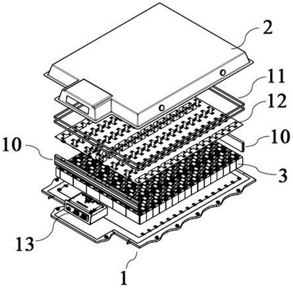
In one embodiment, as shown in fig. 1, the invention provides a battery pack, which includes a case body 1 and a case cover 2 matched with the case body 1, wherein a containing space is formed between the case body 1 and the case cover 2;
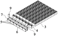
as shown in fig. 2, a cell stacking unit 3 is disposed in the accommodating space, and the cell stacking unit 3 includes at least two cell unit clusters 4 sequentially arranged in the thickness direction; the cell unit cluster 4 includes two rows of cell arrays 5, and each cell array 5 includes at least two cells 6 arranged in sequence along the length direction.
According to the battery pack, a traditional module structure is not used, the battery cores 6 are arranged to form the battery core array 5, the battery core array 5 is combined to form the battery core unit cluster 4, the battery core unit cluster 4 is arranged to form the battery core stacking unit 3, and the battery core stacking unit 3 is directly arranged in the accommodating space between the same battery core stacking unit and the box cover 2, so that the battery pack is directly assembled, the assembly process of the battery pack is simplified, the number of parts is reduced, the size of the battery pack is reduced, the production cost of the battery pack is reduced, and the energy density of the battery pack is improved.
Further, the cell unit cluster 4 further comprises a thermal management plate 7 arranged between the two rows of cell arrays 5, and a liquid flow channel is arranged in the thermal management plate 7;
the box body 1 is provided with a thermal management internal interface 8, and the thermal management internal interface 8 is communicated with the liquid flow channel.
The liquid flow channel is used for realizing the functions of temperature equalization, high-temperature cooling and heat dissipation and low-temperature liquid heating of the battery cell 6.
According to the invention, the thermal management board 7 is physically connected with the box body 1 and is functionally integrated, and the cooling flow channel in the thermal management board 7 is communicated with the thermal management internal interface 8 on the box body 1, so that the liquid cooling function of the battery pack is realized.
Further, the cell unit cluster 4 further includes protection parts 9 disposed at two ends of the cell array 5.
In the invention, the protection part 9 is used for protecting the cell array 5 and preventing the cell array 5 from being directly impacted by the outside.
Further, two rows of cells in the cell array 5 are arranged in a staggered manner.
The cells 6 in the cell array 5 are arranged in a staggered manner to prevent the cell explosion-proof valve of the confluence block plug from exhausting.
Further, in two rows of cells in the cell array 5, the overlapping area of two cells 6 is not greater than one-half of the side area of the cell 6.
When the overlapping area of two battery cells 6 in the battery cell array 5 is larger than half of the side area of the battery cell 6, the exhaust of the battery cell explosion-proof valve is easily blocked by the busbar.
Further, structural adhesive is filled between each cell unit cluster 4 and the box body 1, and elastic heat insulation materials are filled between adjacent cell unit clusters 4; and heat conduction structural adhesive is filled between the cell array 5 and the heat management plate 7, and structural adhesive is filled between adjacent cells 6 of the cell array 5.
According to the invention, the structural adhesive is filled between the cell unit cluster 4 and the box body 1 to restrain the cell unit cluster 4, so that the cell unit cluster 4 is prevented from shifting in the use process of the battery pack.
According to the invention, the elastic heat-insulating material is filled between the adjacent cell unit clusters 4, so that the expansion displacement of the cell 6 caused by charging is absorbed, the heat-insulating effect is achieved, the heat is prevented from being transferred and diffused between the adjacent cell unit clusters 4, and sufficient buffer space is reserved between the adjacent cell unit clusters 4, so that the tolerance generated in the manufacturing process is absorbed.
According to the invention, the heat conduction structure adhesive is filled between the battery cell array 5 and the heat management plate 7, on one hand, the heat conduction structure adhesive is used for fixing the battery cell array 5 to enable the battery cell unit cluster 4 to be an integral structure, so that the integral rigidity of the battery pack is improved, and on the other hand, the heat conduction structure adhesive is used for temperature isolation and equalization to prevent the temperature difference from being too large due to the rapid heat transfer between the battery cell 6 and the heat management plate 7.
According to the invention, the structural adhesive is filled between the adjacent electric cores 6 of the electric core array 5 and is used for improving the anti-shearing capability between the electric cores 6, so that the electric cores 6 of the battery pack are prevented from being dislocated in the using process.
Further, as shown in fig. 3, the cell stacking units 3 are provided with expansion restriction structures 10 at both ends in the arrangement direction of the cell unit clusters 4.
The arrangement of the expansion restricting structure 10 of the present invention is used to absorb the expansion displacement of the cell stacking unit 3 due to charging, and also used to keep a sufficient buffer space between the cell stacking unit 3 and the case cover 2.
Further, a binding band 11 is circumferentially provided on an outer wall of the cell stacking unit 3.
The binding band 11 is used for fixing the battery cell stacking unit 3, and the battery cells 6 in the battery cell stacking unit 3 are prevented from being scattered when the battery pack is used.
The material of the strap 11 of the present invention includes metal straps and/or non-metal straps.
Further, a busbar assembly 12 connected to the cell stacking unit 3 is further disposed in the accommodating space, and the busbar assembly 12 is disposed on the top of the cell stacking unit 3.
The busbar assembly 12 is welded to the pole of the cell 6 in the cell stacking unit 3 by a laser welding process.
Optionally, a positioning hole is provided in the busbar assembly 12, and the positioning hole is used to fix and assemble the busbar assembly 12 on the cell stacking unit 3.
The bus bar is used for realizing series-parallel connection between the electric cores 6 in the electric core stacking unit 3.
Further, an insulating member is disposed in the accommodating space at the top of the busbar assembly 12.
The insulating member of the present invention is used to prevent the short circuit of the battery cell 6.
Further, an electrical interaction unit 13 connected with the busbar assembly 12 is arranged in the accommodating space; the box cover 2 is provided with a high-low voltage plug-in avoiding hole 20, and the electric interaction unit 13 is connected with an electric component outside the battery pack through the high-low voltage plug-in avoiding hole 20.
Optionally, the electrical interaction unit 13 includes an electrical interaction unit panel, and the electrical interaction unit panel seals the high-low voltage plug-in avoiding hole 20 on the box cover 2, so that the cell stacking unit 3 in the accommodating space is protected.
Further, the busbar assembly 12 includes a busbar, and the busbar is connected with a pole on the battery cell 6 in the cell stacking unit 3;
the busbar assembly 12 also includes a flexible collection harness and a first low voltage insert connected to the busbar.
The first low-voltage plug-in and the flexible collecting wire harness are used for collecting and transmitting the voltage and the temperature of the battery pack.
Further, the electrical interaction unit 13 integrates a high voltage plug-in with a second low voltage plug-in;
the panel of the electric interaction unit 13 is provided with a sealing mounting hole, the box cover 2 is provided with a box cover sealing hole, and the bolt passes through the sealing mounting hole and the box cover sealing hole to realize the sealing between the box cover 2 and the panel of the electric interaction unit 13.
The arrangement of the sealing mounting hole is beneficial to the whole sealing of the battery pack, and the sealing requirement of the battery pack is met.
Further, as shown in fig. 4, the cover 2 includes a main cover and an electrical interaction unit cover connected to one end of the main cover;
the battery cell stacking unit 3 and the busbar assembly 12 are disposed between the main body case cover and the case body 1, and the electrical interaction unit 13 is disposed between the electrical interaction unit case cover and the case body 1.
According to the invention, the battery cell stacking unit 3 is arranged between the main box cover and the box body 1, and the electric interaction unit 13 is arranged between the electric interaction unit box cover and the box body 1, so that the space utilization rate between the box cover 2 and the box body 1 can be increased, and the volume of a battery pack is reduced.
Further, the main body cover comprises a main body cover body 14, and the electrical interaction unit cover comprises an electrical interaction unit cover body 15;
the main box cover body 14 and the electric interaction unit box cover body 15 are positioned on the same horizontal plane, the outer edge of the main box cover body 14 extends obliquely downwards to form a main box cover side plate 16, and the outer edge of the electric interaction unit box cover body 15 extends obliquely downwards to form an electric interaction unit box cover side plate 17;
at least one explosion-proof valve mounting opening 18 is formed in the side plate 16 of the main box cover, an explosion-proof valve 19 is mounted on the explosion-proof valve mounting opening 18, and a high-low voltage plug-in avoiding hole 20 is formed in the side plate 17 of the electric interaction unit box cover.
According to the invention, the explosion-proof valve 19 is arranged on the box cover 2, and when the internal air pressure of the battery pack reaches a certain value, the battery pack is exploded from the explosion-proof valve 19 of the box cover 2.
Further, one end of the main body box cover side plate 16 far away from the main body box cover body 14 and one end of the electrical interaction unit box cover side plate 17 far away from the electrical interaction unit box cover body 15 are located on the same horizontal plane, and outer edges of the main body box cover side plate 16 and the electrical interaction unit box cover side plate 17 respectively extend outwards along the horizontal direction to form a box cover sealing surface 21;
at least one sealing surface fixing hole is formed in the box cover sealing surface 21, and sealing surface fixing holes corresponding to the sealing surface fixing holes are formed in the box body 1.
According to the invention, the sealing surface fixing hole arranged on the sealing surface of the box cover is matched with the sealing surface fixing hole arranged on the box body 1 to realize the fixed connection of the box cover 2 and the box body 1, and the sealing surface of the box cover is matched with the box body 1 to realize the sealing requirement of the battery pack.
Further, the cover 2 includes a sheet metal member or a composite material molded member.
The sheet metal part and the composite material molded part are light in weight, the processing technology is simple, and the weight of the battery pack is reduced, and the production cost of the battery pack is reduced.
The material of the composite material mould pressing part comprises any one or combination of at least two of SMC composite materials, PP + glass fiber materials or phase change materials, and typical but non-limiting combinations comprise combinations of the SMC composite materials and the PP + glass fiber materials, combinations of the PP + glass fiber materials and the phase change materials, or combinations of the SMC composite materials, the PP + glass fiber materials and the phase change materials.
Further, as shown in fig. 5, the case 1 includes a bottom plate 22 and an insulating layer 23 provided on a surface of the bottom plate 22 facing the case cover 2.
Alternatively, the length of the cell stacking unit 3 in the arrangement direction of the cell unit clusters 4 may be adjusted by increasing or decreasing the number of the cell unit clusters 4, so as to adjust the length of the battery pack in the arrangement direction of the cell unit clusters 4.
Alternatively, by increasing or decreasing the number of the cells 6 in the cell array 5, the length of the cell stacking unit 3 along the arrangement direction of the cells 6 in the cell array 5 may be adjusted, so as to adjust the length of the battery pack along the arrangement direction of the cells 6 in the cell array 5.
The box body 1 of the battery pack is in a flat design, a frame structure of the box body 1 is omitted, the box body 1 and the battery cell stacking unit 3 can continuously extend to the periphery, and the battery pack can be better adapted to electric automobiles with different wheel bases and different wheel bases while the weight and the cost of the battery pack are reduced.
Optionally, the battery pack further comprises a whole vehicle connection point 25, and the battery pack is fixed on the electric vehicle through the whole vehicle connection point 25.
Further, a thermal management external interface 24 is arranged on a side surface of the bottom plate 22, a thermal management internal interface 8 is arranged on a side surface of the bottom plate 22 facing the case cover 2, and a flow passage is arranged in the bottom plate 22 and communicates the thermal management external interface with the thermal management internal interface.
A cooling flow channel in the heat management plate 7 is communicated with a heat management internal interface 8 on the box body 1, and after liquid in the cooling flow channel flows into the box body 1, interaction between the battery pack and a finished automobile heat management system is realized through a heat management external interface 24.
In another embodiment, the invention provides an electric vehicle, which comprises the battery pack.
Example 1
The embodiment provides a battery pack, which comprises a box body and a box cover matched with the box body, wherein an accommodating space is formed between the box body and the box cover; a battery cell stacking unit is arranged in the accommodating space and comprises five battery cell unit clusters which are sequentially arranged along the thickness direction; the cell unit cluster comprises two rows of cell arrays, and each cell array comprises six cells which are sequentially arranged along the length direction; the cells in the cell array are arranged in a staggered manner, and the quantity of the overlapped cells in the cell array is one third;
the battery cell unit cluster also comprises a heat management plate arranged between the two rows of battery cell arrays, a liquid flow channel is arranged in the heat management plate, a heat management internal interface is arranged on the box body, and the heat management internal interface is communicated with the liquid flow channel; structural adhesive is filled between each cell unit cluster and the box body, and elastic heat insulation materials are filled between adjacent cell unit clusters; heat conducting structural adhesive is filled between the cell array and the heat management plate, and structural adhesive is filled between adjacent cells of the cell array; the cell unit cluster also comprises protection parts arranged at two ends of the cell array; the two ends of the cell stacking unit along the arrangement direction of the cell unit clusters are provided with expansion constraint structural members; a binding band is arranged on the outer wall of the battery cell stacking unit along the circumferential direction;
a bus bar assembly connected with the battery cell stacking unit is further arranged in the accommodating space and arranged at the top of the battery cell stacking unit; the accommodating space is also internally provided with an insulating part positioned at the top of the bus bar component;
an electric interaction unit connected with the bus bar assembly is further arranged in the accommodating space; the box cover is provided with a high-low voltage plug-in avoiding hole, and the electrical interaction unit is electrically connected with an external electrical appliance through the high-low voltage plug-in avoiding hole; the bus bar assembly comprises a bus bar, and the bus bar is connected with the pole on the battery cell in the battery cell stacking unit; the busbar assembly further comprises a first low-voltage plug-in and a flexible connector which are connected with the busbar; the electric interaction unit integrates a high-voltage plug-in and a second low-voltage plug-in, a sealing mounting hole is formed in a panel of the electric interaction unit, and the high-voltage plug-in and the second low-voltage plug-in are electrically connected with an external electric appliance through the sealing mounting hole respectively;
the box cover comprises a main box cover and an electric interaction unit box cover connected with one end of the main box cover, the electric core stacking unit and the bus bar assembly are arranged between the main box cover and the box body, and the electric interaction unit is arranged between the electric interaction unit box cover and the box body; the main box cover comprises a main box cover body, the electric interaction unit box cover comprises an electric interaction unit box cover body, the main box cover body and the electric interaction unit box cover body are positioned on the same horizontal plane, the outer edge of the main box cover body extends downwards in an inclined mode to form a main box cover side plate, the outer edge of the electric interaction unit box cover body extends downwards in an inclined mode to form an electric interaction unit box cover side plate, six explosion-proof valve mounting openings are formed in the main box cover side plate, explosion-proof valves are mounted on the explosion-proof valve mounting openings, and high-low voltage plug-in avoiding holes are formed in the electric interaction unit box cover side plate; the end, far away from the main box cover body, of the main box cover side plate and the end, far away from the electric interaction unit box cover body, of the electric interaction unit box cover side plate are located on the same horizontal plane, the outer edges of the main box cover side plate and the electric interaction unit box cover side plate respectively extend outwards along the horizontal direction to form a box cover sealing surface, eight sealing surface fixing holes are formed in the box cover sealing surface, and sealing surface fixing holes corresponding to the box cover sealing surface fixing holes are formed in the box body; the case cover comprises an SMC composite molded piece;
the box body comprises a bottom plate and an insulating layer arranged on the surface of one side, facing the box cover, of the bottom plate; the side surface of the bottom plate is provided with a thermal management external interface, and the surface of one side of the bottom plate, which faces the box cover, is provided with a thermal management internal interface.
The embodiment also provides an electric automobile which comprises the battery pack.
Example 2
The embodiment provides a battery pack, which comprises a box body and a box cover matched with the box body, wherein an accommodating space is formed between the box body and the box cover; a battery cell stacking unit is arranged in the accommodating space and comprises two battery cell unit clusters which are sequentially arranged along the thickness direction; the cell unit cluster comprises two rows of cell arrays, and each cell array comprises six cells which are sequentially arranged along the length direction; the battery cells in the battery cell array are arranged in a staggered manner, and the quantity of the battery cells overlapped in the battery cell array is one fourth;
the cell unit cluster also comprises a heat management plate arranged between the two rows of cell arrays, a liquid flow channel is arranged in the heat management plate, a heat management internal interface is arranged on the box body, and the heat management internal interface is communicated with the liquid flow channel; structural adhesive is filled between each cell unit cluster and the box body, and elastic heat insulation materials are filled between adjacent cell unit clusters; heat conducting structural adhesive is filled between the cell array and the heat management plate, and structural adhesive is filled between adjacent cells of the cell array; the cell unit cluster also comprises protection parts arranged at two ends of the cell array; the two ends of the cell stacking unit along the arrangement direction of the cell unit clusters are provided with expansion constraint structural members; a binding band is arranged on the outer wall of the battery cell stacking unit along the circumferential direction;
a bus bar assembly connected with the battery cell stacking unit is further arranged in the accommodating space and arranged at the top of the battery cell stacking unit; the accommodating space is also internally provided with an insulating part positioned at the top of the bus bar component;
an electric interaction unit connected with the bus bar assembly is further arranged in the accommodating space; the box cover is provided with a high-low voltage plug-in avoiding hole, and the electrical interaction unit is electrically connected with an external electrical appliance through the high-low voltage plug-in avoiding hole; the bus bar assembly comprises a bus bar, and the bus bar is connected with the pole on the battery cell in the battery cell stacking unit; the busbar assembly further comprises a first low-voltage plug-in and a flexible connector which are connected with the busbar; the electric interaction unit integrates a high-voltage plug-in and a second low-voltage plug-in, a sealing mounting hole is formed in a panel of the electric interaction unit, and the high-voltage plug-in and the second low-voltage plug-in are respectively electrically connected with an external electric appliance through the sealing mounting hole.
The box cover comprises a main box cover and an electric interaction unit box cover connected with one end of the main box cover, the electric core stacking unit and the bus bar assembly are arranged between the main box cover and the box body, and the electric interaction unit is arranged between the electric interaction unit box cover and the box body; the main box cover comprises a main box cover body, the electric interaction unit box cover comprises an electric interaction unit box cover body, the main box cover body and the electric interaction unit box cover body are positioned on the same horizontal plane, the outer edge of the main box cover body extends downwards in an inclined mode to form a main box cover side plate, the outer edge of the electric interaction unit box cover body extends downwards in an inclined mode to form an electric interaction unit box cover side plate, an explosion-proof valve mounting opening is formed in the main box cover side plate, an explosion-proof valve is mounted on the explosion-proof valve mounting opening, and a high-low voltage plug-in avoiding hole is formed in the electric interaction unit box cover side plate; the end, far away from the main box cover body, of the main box cover side plate and the end, far away from the electric interaction unit box cover body, of the electric interaction unit box cover side plate are located on the same horizontal plane, the outer edges of the main box cover side plate and the electric interaction unit box cover side plate respectively extend outwards along the horizontal direction to form a box cover sealing surface, eight sealing surface fixing holes are formed in the box cover sealing surface, and sealing surface fixing holes corresponding to the box cover sealing surface fixing holes are formed in the box body; the box cover comprises a sheet metal part;
the box body comprises a bottom plate and an insulating layer arranged on the surface of one side, facing the box cover, of the bottom plate; and a heat management external interface is arranged on the side surface of the bottom plate, and a heat management internal interface is arranged on the surface of one side of the bottom plate, which faces the box cover.
The embodiment also provides an electric automobile which comprises the battery pack.
Example 3
The embodiment provides a battery pack, which comprises a box body and a box cover matched with the box body, wherein an accommodating space is formed between the box body and the box cover; a battery cell stacking unit is arranged in the accommodating space and comprises six battery cell unit clusters which are sequentially arranged along the thickness direction; the cell unit cluster comprises two rows of cell arrays, and each cell array comprises two cells which are sequentially arranged along the length direction; the battery cells in the battery cell array are arranged in a staggered mode, and the number of the overlapped battery cells in the battery cell array is one half;
the cell unit cluster also comprises a heat management plate arranged between the two rows of cell arrays, a liquid flow channel is arranged in the heat management plate, a heat management internal interface is arranged on the box body, and the heat management internal interface is communicated with the liquid flow channel; structural adhesive is filled between the cell unit clusters and the box body, and elastic heat insulation materials are filled between the adjacent cell unit clusters; heat conducting structural adhesive is filled between the cell array and the heat management plate, and structural adhesive is filled between adjacent cells of the cell array; the cell unit cluster also comprises protection parts arranged at two ends of the cell array; the two ends of the cell stacking unit along the arrangement direction of the cell unit clusters are provided with expansion constraint structural members; a binding band is arranged on the outer wall of the battery cell stacking unit along the circumferential direction;
a bus bar assembly connected with the battery cell stacking unit is further arranged in the accommodating space and arranged at the top of the battery cell stacking unit; the accommodating space is also internally provided with an insulating part positioned at the top of the bus bar component;
an electric interaction unit connected with the bus bar assembly is further arranged in the accommodating space; the box cover is provided with a high-low voltage plug-in avoiding hole, and the electrical interaction unit is electrically connected with an external electrical appliance through the high-low voltage plug-in avoiding hole; the bus bar assembly comprises a bus bar, and the bus bar is connected with the pole on the battery cell in the battery cell stacking unit; the busbar assembly further comprises a first low-voltage plug-in and a flexible connector which are connected with the busbar; the electric interaction unit integrates a high-voltage plug-in and a second low-voltage plug-in, a sealing mounting hole is formed in a panel of the electric interaction unit, and the high-voltage plug-in and the second low-voltage plug-in are electrically connected with an external electric appliance through the sealing mounting hole respectively;
the box cover comprises a main box cover and an electric interaction unit box cover connected with one end of the main box cover, the electric core stacking unit and the bus bar assembly are arranged between the main box cover and the box body, and the electric interaction unit is arranged between the electric interaction unit box cover and the box body; the main box cover comprises a main box cover body, the electric interaction unit box cover comprises an electric interaction unit box cover body, the main box cover body and the electric interaction unit box cover body are positioned on the same horizontal plane, the outer edge of the main box cover body extends downwards in an inclined mode to form a main box cover side plate, the outer edge of the electric interaction unit box cover body extends downwards in an inclined mode to form an electric interaction unit box cover side plate, eight explosion-proof valve mounting openings are formed in the main box cover side plate, explosion-proof valves are mounted on the explosion-proof valve mounting openings, and high-low voltage plug-in avoiding holes are formed in the electric interaction unit box cover side plate; the end, far away from the main box cover body, of the main box cover side plate and the end, far away from the electric interaction unit box cover body, of the electric interaction unit box cover side plate are located on the same horizontal plane, the outer edges of the main box cover side plate and the electric interaction unit box cover side plate respectively extend outwards along the horizontal direction to form a box cover sealing surface, a sealing surface fixing hole is formed in the box cover sealing surface, and a sealing surface fixing hole corresponding to the box cover sealing surface fixing hole is formed in the box body; the case cover comprises a phase change material molded piece;
the box body comprises a bottom plate and an insulating layer arranged on the surface of one side, facing the box cover, of the bottom plate; the side surface of the bottom plate is provided with a thermal management external interface, and the surface of one side of the bottom plate, which faces the box cover, is provided with a thermal management internal interface.
The embodiment also provides an electric automobile which comprises the battery pack.
The applicant declares that the above description is only a specific embodiment of the present invention, but the scope of the present invention is not limited thereto, and it should be understood by those skilled in the art that any changes or substitutions that can be easily conceived by those skilled in the art within the technical scope of the present invention are within the scope and disclosure of the present invention.