CN115069054A - Energy-saving environment-friendly leakage-free efficient dust removal device and dust removal method thereof - Google Patents
Energy-saving environment-friendly leakage-free efficient dust removal device and dust removal method thereof Download PDFInfo
- Publication number
- CN115069054A CN115069054A CN202210942135.4A CN202210942135A CN115069054A CN 115069054 A CN115069054 A CN 115069054A CN 202210942135 A CN202210942135 A CN 202210942135A CN 115069054 A CN115069054 A CN 115069054A
- Authority
- CN
- China
- Prior art keywords
- dust removal
- fixing plate
- air
- filter element
- gas
- Prior art date
- Legal status (The legal status is an assumption and is not a legal conclusion. Google has not performed a legal analysis and makes no representation as to the accuracy of the status listed.)
- Granted
Links
- 239000000428 dust Substances 0.000 title claims abstract description 100
- 238000000034 method Methods 0.000 title claims abstract description 28
- 238000001914 filtration Methods 0.000 claims abstract description 16
- 230000005540 biological transmission Effects 0.000 claims description 27
- 238000007789 sealing Methods 0.000 claims description 13
- 239000002245 particle Substances 0.000 claims description 6
- 238000000605 extraction Methods 0.000 claims description 4
- 230000033001 locomotion Effects 0.000 claims description 4
- 230000008602 contraction Effects 0.000 claims description 3
- 230000005484 gravity Effects 0.000 claims description 3
- 239000007789 gas Substances 0.000 description 46
- WSFSSNUMVMOOMR-UHFFFAOYSA-N Formaldehyde Chemical compound O=C WSFSSNUMVMOOMR-UHFFFAOYSA-N 0.000 description 12
- 239000012717 electrostatic precipitator Substances 0.000 description 3
- CBENFWSGALASAD-UHFFFAOYSA-N Ozone Chemical compound [O-][O+]=O CBENFWSGALASAD-UHFFFAOYSA-N 0.000 description 2
- 230000007613 environmental effect Effects 0.000 description 2
- 239000000758 substrate Substances 0.000 description 2
- UGFAIRIUMAVXCW-UHFFFAOYSA-N Carbon monoxide Chemical compound [O+]#[C-] UGFAIRIUMAVXCW-UHFFFAOYSA-N 0.000 description 1
- QVGXLLKOCUKJST-UHFFFAOYSA-N atomic oxygen Chemical compound [O] QVGXLLKOCUKJST-UHFFFAOYSA-N 0.000 description 1
- 230000009286 beneficial effect Effects 0.000 description 1
- 239000003054 catalyst Substances 0.000 description 1
- 238000005516 engineering process Methods 0.000 description 1
- 239000003546 flue gas Substances 0.000 description 1
- 239000011521 glass Substances 0.000 description 1
- 238000009776 industrial production Methods 0.000 description 1
- 238000009434 installation Methods 0.000 description 1
- 238000004519 manufacturing process Methods 0.000 description 1
- 239000001301 oxygen Substances 0.000 description 1
- 229910052760 oxygen Inorganic materials 0.000 description 1
- 239000000843 powder Substances 0.000 description 1
Images



Classifications
-
- B—PERFORMING OPERATIONS; TRANSPORTING
- B01—PHYSICAL OR CHEMICAL PROCESSES OR APPARATUS IN GENERAL
- B01D—SEPARATION
- B01D50/00—Combinations of methods or devices for separating particles from gases or vapours
- B01D50/20—Combinations of devices covered by groups B01D45/00 and B01D46/00
-
- Y—GENERAL TAGGING OF NEW TECHNOLOGICAL DEVELOPMENTS; GENERAL TAGGING OF CROSS-SECTIONAL TECHNOLOGIES SPANNING OVER SEVERAL SECTIONS OF THE IPC; TECHNICAL SUBJECTS COVERED BY FORMER USPC CROSS-REFERENCE ART COLLECTIONS [XRACs] AND DIGESTS
- Y02—TECHNOLOGIES OR APPLICATIONS FOR MITIGATION OR ADAPTATION AGAINST CLIMATE CHANGE
- Y02A—TECHNOLOGIES FOR ADAPTATION TO CLIMATE CHANGE
- Y02A50/00—TECHNOLOGIES FOR ADAPTATION TO CLIMATE CHANGE in human health protection, e.g. against extreme weather
- Y02A50/20—Air quality improvement or preservation, e.g. vehicle emission control or emission reduction by using catalytic converters
- Y02A50/2351—Atmospheric particulate matter [PM], e.g. carbon smoke microparticles, smog, aerosol particles, dust
Landscapes
- Chemical & Material Sciences (AREA)
- Chemical Kinetics & Catalysis (AREA)
- Filtering Of Dispersed Particles In Gases (AREA)
Abstract
The invention discloses an energy-saving, environment-friendly and leakage-free high-efficiency dust removal device and a dust removal method thereof, wherein the device comprises a first device shell, wherein a foreign matter collection cavity is arranged at the lower end of the first device shell; one side of one of the second fixing plates is provided with a first fixing plate, an air extractor is arranged between the first fixing plate and the second fixing plate, a connecting plate is arranged inside the containing cavity, a rotating connecting shaft is arranged between the connecting plate and the second fixing plate, and the outer portion of the connecting plate is in sliding connection with the containing cavity. The foreign matters adhered to the outside of the limiting cover are discharged and cleaned, the replacement frequency of the first dust removal filter element is reduced, the environment friendliness of the device during use is improved, the first dust removal filter element rotates by taking the rotating connecting shaft as a circle center between the second fixing plate and the third fixing plate, the air exhaust device is driven to rotate in a rotating mode, the contact frequency between the first dust removal filter element and required filtering gas can be improved in the rotating process, and the first dust removal filter element can actively contact the required filtering gas.
Description
Technical Field
The invention relates to the technical field of dust removal, in particular to an energy-saving, environment-friendly and leakage-free efficient dust removal device and a dust removal method thereof.
Background
Along with the progress and the industrial evolution of science and technology, the efficiency and the scale of people's production progressively promote, produced bits of broken glass can influence the environment of nature in the industry, in order to avoid natural environment's influence, people design a dust collector, dust collector is the equipment of separating the dust from the flue gas and is called dust remover or dust collecting equipment, the dust remover is the facility of common use in boiler and the industrial production, along with the continuous promotion of dust removal technique, people's dust removal mode is various, the device that corresponds the dust removal mode also produces thereupon.
If the chinese patent with the publication number of CN104324810B discloses an electrostatic precipitator, including an electrostatic precipitator assembly 100, the electrostatic precipitator further includes: the formaldehyde removing assembly comprises a substrate 200 and a formaldehyde removing catalyst coated on the substrate 200, and the formaldehyde removing assembly is provided with a plurality of first flow guide through holes; the ozone reduction net 700 reduces ozone into oxygen, and the electrostatic dust collection device has the function of removing formaldehyde.
However, in the actual use process of the device, air is filtered only through the transverse filter screen, the service life of the filter element in the device is short, frequent replacement is needed, the environmental protection capability is poor, and the filter element replacement process is complicated, so that the existing requirements are not met.
Disclosure of Invention
The invention aims to provide an energy-saving, environment-friendly and leakage-free high-efficiency dust removal device and a dust removal method thereof, and aims to solve the problems that the filter element of the dust removal device in the background art needs to be frequently replaced, so that the use process is not environment-friendly, and the filter element replacement efficiency is low.
In order to achieve the purpose, the invention provides the following technical scheme: an energy-saving environment-friendly leakage-free high-efficiency dust removal device and a dust removal method thereof comprise a first device shell, wherein a first air filter cavity is arranged inside the first device shell, an air transmission port is formed in the upper end of one side of the first air filter cavity, and a foreign matter collection cavity is formed in the lower end of the first device shell;
the second device shell is arranged in the middle of the inside of the first device shell, a pair of second fixing plates is arranged inside the second device shell, four pairs of second fixing plates are longitudinally arranged on each second fixing plate, a first fixing plate is arranged on one side of one second fixing plate, an air exhaust device is arranged between each first fixing plate and each second fixing plate, a third fixing plate is arranged on the other side of each second fixing plate, an accommodating cavity is formed inside each third fixing plate, a connecting plate is arranged inside each accommodating cavity, a rotating connecting shaft is arranged between each connecting plate and each second fixing plate, the outer portion of each connecting plate is connected with the corresponding accommodating cavity in a sliding mode, each connecting plate is connected with the corresponding rotating connecting shaft in a rotating mode, and a plurality of hydraulic telescopic rods are annularly arranged on one side of each first fixing plate;
the gas transmission pipeline is arranged on one side of the first fixing plate, one side of the first fixing plate is hermetically connected with one end of the gas transmission pipeline, a plurality of gas outlets are transversely and uniformly distributed at the upper end and the lower end of the outer part of the gas transmission pipeline, and the gas outlets are hermetically connected with the gas transmission pipeline.
Preferably, the upper end of one side in the first air filtering cavity is provided with an air flow limiting plate, two ends of the air flow limiting plate are fixedly connected with the second device shell and the first device shell respectively, one side of the air flow limiting plate is longitudinally provided with a plurality of air guide strips, and the air guide strips are fixedly connected with the first device shell.
Preferably, the outside of gas vent is provided with first dust removal filter element, the outside both sides of first dust removal filter element all are provided with the centre gripping mount, two one side of centre gripping mount respectively with first fixed plate and second fixed plate fixed connection.
Preferably, the outside of third fixed plate is provided with vertical sliding rail, and vertical sliding rail and third fixed plate china east link, the upper end of third fixed plate is provided with the transmission connecting rod, the one end of transmission connecting rod is provided with the second handle, the inside upper end of second handle is provided with pressure sensor.
Preferably, a second air filtering cavity is arranged at the lower end of the interior of the second device shell, a limiting cover is arranged at the upper end of the second device shell, and the lower end of one side of the limiting cover is rotatably connected with one side of the upper end of the first device shell through a second rotating shaft.
Preferably, both ends all are provided with the gas vent around the outside of restriction cover, two the inside of gas vent all is provided with the second and removes dust the filter core.
Preferably, a sealing baffle plate is arranged at the lower end in the foreign matter collecting cavity.
Preferably, one side of the upper end of the limiting cover is provided with a first handle, and the first handle is fixedly connected with the limiting cover.
Preferably, the sealing baffle is rotatably connected with the first device shell through a first rotating shaft.
The dust removal method of the energy-saving environment-friendly leakage-free high-efficiency dust removal device comprises the following steps:
firstly, extracting external gas to be filtered by an air extracting device and conveying the gas to the interior of the device through an air conveying port, wherein the gas is limited by an air flow limiting plate and an air guide strip after entering the device, and then the gas is conveyed to the interior of the device in a matching manner to enable dust flow to rotate, and dust particles are separated from the gas flow by virtue of centrifugal force and collected on the wall of the device and then fall into a foreign matter collecting cavity;
step two, after the gas rotates to the lower end of the first device shell, the gas rotates to the upper end in the second device shell, and the gas can actively contact the first dedusting filter element in the rotating process;
when the first dust removal filter element is contacted with air and is filtered, the output device drives the second fixing plate to rotate, the rotation of the second fixing plate drives the first dust removal filter element to rotate, and the contact frequency of the first dust removal filter element and the air can be improved in the rotating process;
step four, when the first dust removal filter element is cleaned, air can be extracted through the air extraction device, the air is conveyed through the air conveying pipeline and then is exhausted from the air exhaust port, the exhausted air can exhaust foreign matters adhered to the outside of the first dust removal filter element, and the exhausted foreign matters can fall into the foreign matter collecting cavity due to gravity;
step five, when the first dedusting filter element is replaced, a user pulls the second handle, the second handle can detect pressure through the pressure sensor after being pulled, and after the pressure is detected, the third fixing plate is pushed through the telescopic device to drive the first dedusting filter element to longitudinally move upwards in the longitudinal sliding rail, and all the first dedusting filter elements can be exposed through the longitudinal upwards movement;
step six, the extension through hydraulic telescoping rod promotes the second fixed plate, and the second fixed plate transversely accepts the intracavity through rotating connecting axle and connecting plate and slides, and the extension can drive the opposite lateral shifting of a pair of centre gripping mount to lose the restriction to first dust removal filter element, can change first dust removal filter element from this, and it fixes to the first dust removal filter element after changing to accomplish through hydraulic telescoping rod shrink.
Compared with the prior art, the invention has the beneficial effects that:
1. the invention arranges the second fixing plates at the two sides of the outer part of the first dedusting filter core, one side of one of the second fixing plates is provided with the air exhaust device, one side of the air exhaust device is provided with the first fixing plate, the inner part of the first dedusting filter core is provided with the gas transmission pipeline, when the first dedusting filter core is used for filtering in the actual use process, the gas extracted by the air exhaust device is transmitted by the gas transmission pipeline and is exhausted by the exhaust port, foreign matters adhered to the outer part of the limiting cover are exhausted and cleaned, the replacement frequency of the first dedusting filter core is reduced, the environmental protection when the device is used is improved, on the other hand, in the actual use process, the air exhaust device is driven to rotate by the rotation between the second fixing plate and the third fixing plate by taking the rotating connecting shaft as the circle center, the contact frequency between the first dedusting filter core and the required filtering gas can be improved by the rotating process, so that the first dust removal filter element can actively contact the gas to be filtered, and the filtering efficiency is improved.
2. According to the invention, the transmission connecting rod is arranged at one end of one of the third fixing plates, the second handle is arranged at one end of the transmission connecting rod, the pressure sensor is arranged at the upper end inside the second handle, the plurality of hydraulic telescopic rods are annularly arranged between the first fixing plate and the other one of the second fixing plates, in the actual use process, the clamping fixing frame can be driven to transversely move by telescopic pushing of the hydraulic telescopic rods, one of the second fixing plates can be pushed to transversely move while transversely moving, and the second fixing plate is accommodated in the accommodating cavity, so that the first dust removal filter core can be conveniently replaced, the efficiency of replacing the first dust removal filter core is high, the first dust removal filter core is convenient to replace, the first dust removal filter core can be clamped by contraction of the hydraulic telescopic rods, and the stability in installation is improved by clamping.
3. The invention arranges an air flow limiting plate at one side of the inner part of the first device shell, a second device shell is arranged at one side of the air flow limiting plate, a first dedusting filter core is arranged in the second device shell, in the actual use process, the gas is extracted by an external air extractor, extracted and conveyed to the inside of the device, and after being limited by the air flow limiting plate and the air guide strip, the dust-collecting chamber can guide the gas, guide the gas and match the conveying angle of the gas to make the dust flow rotate, separate the dust particles from the gas flow by means of centrifugal force and collect the dust particles on the wall of the chamber, and then fall into the foreign matter collecting chamber, and after the lower extreme that gas received first device shell restricted, vertical upwards rotary motion, the exhaust in-process of rotary motion can pass through first dust removal filter core to filter once more, but the direct effectual improvement filtration efficiency of secondary filtration.
Drawings
FIG. 1 is a front view of the overall internal structure of the present invention;
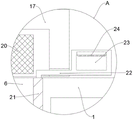
FIG. 2 is an enlarged view of a portion of the area A of FIG. 1 in accordance with the present invention;
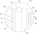
FIG. 3 is an enlarged view of a portion of the area B of FIG. 1 in accordance with the present invention;
FIG. 4 is an enlarged view of a portion of the invention in the area C of FIG. 1;
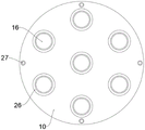
FIG. 5 is a side view of the first fixing plate and the clamping fixture according to the present invention;
FIG. 6 is a perspective view of the external structure of the confinement shield of the present invention;
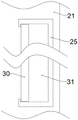
fig. 7 is a schematic view of the internal structure of the longitudinal sliding rail of the present invention.
In the figure: 1. a first device housing; 2. an air flow restricting plate; 3. an air guide strip; 4. a first air filtration chamber; 5. a second device housing; 6. a second air filter cavity; 7. a foreign matter collection chamber; 8. sealing the baffle; 9. a first rotating shaft; 10. a first fixing plate; 11. a second fixing plate; 12. rotating the connecting shaft; 13. an air extraction device; 14. a gas delivery pipeline; 15. an exhaust port; 16. a first dust-removing filter element; 17. a confinement shield; 18. a second rotating shaft; 19. a first handle; 20. a second dust removal filter element; 21. a longitudinal sliding rail; 22. a transmission connecting rod; 23. a second handle; 24. a pressure sensor; 25. a third fixing plate; 26. clamping the fixing frame; 27. a hydraulic telescopic rod; 28. an exhaust port; 29. a gas transmission port; 30. a connecting plate; 31. an accommodating cavity.
Detailed Description
The technical solutions in the embodiments of the present invention will be clearly and completely described below with reference to the drawings in the embodiments of the present invention, and it is obvious that the described embodiments are only a part of the embodiments of the present invention, and not all of the embodiments.
Referring to fig. 1-7, an embodiment of the present invention is shown: an energy-saving environment-friendly leakage-free high-efficiency dust removal device and a dust removal method thereof comprise a first device shell 1, wherein a first air filter cavity 4 is arranged inside the first device shell 1, the upper end of one side of the first air filter cavity 4 is provided with an air transmission port 29, and the lower end of the first device shell 1 is provided with a foreign matter collection cavity 7;
the second device shell 5 is arranged in the middle of the inside of the first device shell 1, a pair of second fixing plates 11 is arranged in the second device shell 5, four pairs of second fixing plates 11 are longitudinally arranged on the second fixing plates 11, a first fixing plate 10 is arranged on one side of one second fixing plate 11, an air extractor 13 is arranged between the first fixing plate 10 and the second fixing plate 11, a third fixing plate 25 is arranged on the other side of the two second fixing plates 11, an accommodating cavity 31 is arranged in the third fixing plate 25, a connecting plate 30 is arranged in the accommodating cavity 31, a rotating connecting shaft 12 is arranged between the connecting plate 30 and the second fixing plate 11, the outer portion of the connecting plate 30 is in sliding connection with the accommodating cavity 31, the connecting plate 30 is in rotating connection with the rotating connecting shaft 12, and a plurality of hydraulic telescopic rods 27 are annularly arranged on one side of the first fixing plate 10;
the gas transmission pipeline 14 is arranged on one side of the first fixing plate 10, one side of the first fixing plate 10 is connected with one end of the gas transmission pipeline 14 in a sealing mode, a plurality of gas outlets 15 are transversely and uniformly distributed at the upper end and the lower end of the outer portion of the gas transmission pipeline 14, and the gas outlets 15 are connected with the gas transmission pipeline 14 in a sealing mode.
Referring to fig. 1, an air flow limiting plate 2 is disposed at an upper end of one side inside a first air filtering cavity 4, two ends of the air flow limiting plate 2 are fixedly connected to a second device housing 5 and a first device housing 1, a plurality of air guide strips 3 are longitudinally disposed at one side of the air flow limiting plate 2, the air guide strips 3 are fixedly connected to the first device housing 1, and air can be guided by the air flow limiting plate 2 and the air guide strips 3.
Referring to fig. 1, 2, 3, 4 and 5, a first dust-removing filter core 16 is disposed outside the exhaust port 15, clamping fixing frames 26 are disposed on both sides of the outside of the first dust-removing filter core 16, one side of each of the two clamping fixing frames 26 is fixedly connected to the first fixing plate 10 and the second fixing plate 11, and the first dust-removing filter core 16 can be fixed by clamping the clamping fixing frames 26.
Referring to fig. 1, 2, 3, 4, 5 and 7, a longitudinal sliding rail 21 is disposed outside the third fixing plate 25, the longitudinal sliding rail 21 is connected to the third fixing plate 25 in a east-west manner, a transmission connecting rod 22 is disposed at an upper end of the third fixing plate 25, a second handle 23 is disposed at one end of the transmission connecting rod 22, a pressure sensor 24 is disposed at an upper end inside the second handle 23, and a user can contact the pressure sensor 24 after pulling the second handle 23, so that the user can detect the telescopic device at the lower end inside the longitudinal sliding rail 21 through the pressure sensor 24, and pull the first dust-removing filter cores 16 to move longitudinally upward.
Referring to fig. 1, 2, 3, 4 and 5, a second air filter chamber 6 is disposed at the lower end of the inside of the second device housing 5, a limiting cover 17 is disposed at the upper end of the second device housing 5, the lower end of one side of the limiting cover 17 is rotatably connected to one side of the upper end of the first device housing 1 through a second rotating shaft 18, the rotation of the limiting cover 17 can open the inside of the second device housing 5, and the first dust-removing filter element 16 can be conveniently replaced by a user after limitation.
Referring to fig. 1, 2 and 6, the front end and the rear end of the outside of the limiting cover 17 are provided with exhaust ports 28, the second dust-removing filter element 20 is disposed inside each of the two exhaust ports 28, the gas to be exhausted is filtered by the second dust-removing filter element 20 inside the exhaust port 28, and the outside foreign matters can be prevented from entering the inside of the device after being limited by the second dust-removing filter element 20 during filtering.
Referring to fig. 1, a sealing baffle 8 is disposed at the lower end of the interior of the foreign matter collecting chamber 7, and the filtered powder is supported and limited by the sealing baffle 8.
Referring to fig. 1, a first handle 19 is disposed on one side of the upper end of the restriction cover 17, and the first handle 19 is fixedly connected to the restriction cover 17, so that the position of the restriction cover 17 can be adjusted by pulling the first handle 19.
Referring to fig. 1, the sealing baffle 8 is rotatably connected to the first device housing 1 via a first rotating shaft 9, and the position of the sealing baffle 8 can be adjusted by rotating the first rotating shaft 9.
The dust removal method of the energy-saving environment-friendly leakage-free high-efficiency dust removal device comprises the following steps:
firstly, extracting external gas to be filtered by an air extracting device and conveying the gas to the interior of the device through an air conveying port 29, enabling dust gas flow to rotate after the gas enters the device and is limited by an air flow limiting plate 2 and an air guide strip 3 in a matching way according to the angle of conveying the gas into the interior of the device, separating dust particles from the gas flow by virtue of centrifugal force, collecting the dust particles on the wall of the device, and then falling into a foreign matter collecting cavity 7;
step two, after the gas rotates to the lower end of the first device shell 1, the gas rotates to the upper end in the second device shell 5, and the gas can actively contact the first dedusting filter element 16 in the rotating process;
step three, when the first dust removing filter element 16 contacts air and filters the air, the output device drives the second fixing plate 11 to rotate, the rotation of the second fixing plate 11 drives the first dust removing filter element 16 to rotate, and the contact frequency of the first dust removing filter element 16 and the air can be improved in the rotating process;
step four, when the first dust removal filter element 16 is cleaned, air can be extracted through the air extraction device 13, the air is conveyed through the air conveying pipeline 14 and then is exhausted through the exhaust port 15, the exhausted air can exhaust foreign matters adhered to the outside of the first dust removal filter element 16, and the exhausted foreign matters can fall into the foreign matter collection cavity 7 due to gravity;
step five, when replacing the first dust removing filter element 16, a user pulls the second handle 23, the second handle 23 detects pressure through the pressure sensor 24 after being pulled, and after detecting the pressure, the third fixing plate 25 is pushed through the telescopic device to drive the first dust removing filter element 16 to longitudinally move upwards in the longitudinal sliding rail 21, and all the first dust removing filter elements 16 can be exposed after longitudinally moving upwards;
and step six, the second fixing plate 11 is pushed by the extension of the hydraulic telescopic rod 27, the second fixing plate 11 transversely slides in the accommodating cavity 31 by rotating the connecting shaft 12 and the connecting plate 30, the extension can drive the pair of clamping fixing frames 26 to reversely and transversely move, and the limitation on the first dust removing filter element 16 is lost, so that the first dust removing filter element 16 can be replaced, and the replaced first dust removing filter element 16 is fixed by the contraction of the hydraulic telescopic rod 27 after the replacement.
It will be evident to those skilled in the art that the invention is not limited to the details of the foregoing illustrative embodiments, and that the present invention may be embodied in other specific forms without departing from the spirit or essential attributes thereof. The present embodiments are therefore to be considered in all respects as illustrative and not restrictive, the scope of the invention being indicated by the appended claims rather than by the foregoing description, and all changes which come within the meaning and range of equivalency of the claims are therefore intended to be embraced therein. Any reference sign in a claim should not be construed as limiting the claim concerned.
Claims (10)
1. The utility model provides an energy-concerving and environment-protective leak-free high-efficient dust collector, includes first device shell (1), the inside of first device shell (1) is provided with first filtration chamber (4), the upper end of first filtration chamber (4) one side is provided with gas transmission mouth (29), the lower extreme of first device shell (1) is provided with foreign matter collection chamber (7), its characterized in that:
a second device housing (5) disposed in the middle of the first device housing (1), wherein a pair of second fixing plates (11) is disposed inside the second device housing (5), four pairs of second fixing plates (11) are longitudinally disposed, a first fixing plate (10) is disposed on one side of one second fixing plate (11), an air extractor (13) is disposed between the first fixing plate (10) and the second fixing plate (11), a third fixing plate (25) is disposed on the other side of the two second fixing plates (11), an accommodating cavity (31) is disposed inside the third fixing plate (25), a connecting plate (30) is disposed inside the accommodating cavity (31), a rotating connecting shaft (12) is disposed between the connecting plate (30) and the second fixing plate (11), and the outside of the connecting plate (30) is slidably connected with the accommodating cavity (31), the connecting plate (30) is rotatably connected with the rotating connecting shaft (12), and a plurality of hydraulic telescopic rods (27) are annularly arranged on one side of the first fixing plate (10);
the gas transmission pipeline (14) is arranged on one side of the first fixing plate (10), one side of the first fixing plate (10) is connected with one end of the gas transmission pipeline (14) in a sealing mode, a plurality of gas outlets (15) are transversely and uniformly distributed at the upper end and the lower end of the outer portion of the gas transmission pipeline (14), and the gas outlets (15) are connected with the gas transmission pipeline (14) in a sealing mode.
2. The energy-saving environment-friendly leakage-free high-efficiency dust removal device as claimed in claim 1, characterized in that: the air filter is characterized in that an air flow limiting plate (2) is arranged at the upper end of one side inside the first air filtering cavity (4), two ends of the air flow limiting plate (2) are fixedly connected with the second device shell (5) and the first device shell (1) respectively, a plurality of air flow guide strips (3) are longitudinally arranged on one side of the air flow limiting plate (2), and the air flow guide strips (3) are fixedly connected with the first device shell (1).
3. The energy-saving environment-friendly leakage-free high-efficiency dust removal device as claimed in claim 2, wherein: the dust removing filter is characterized in that a first dust removing filter core (16) is arranged outside the exhaust port (15), clamping fixing frames (26) are arranged on two sides of the outside of the first dust removing filter core (16), and one side of each clamping fixing frame (26) is fixedly connected with the first fixing plate (10) and the second fixing plate (11) respectively.
4. The energy-saving environment-friendly leakage-free high-efficiency dust removal device as claimed in claim 3, characterized in that: the outside of third fixed plate (25) is provided with vertical sliding rail (21), and vertical sliding rail (21) links with third fixed plate (25) china east, the upper end of third fixed plate (25) is provided with transmission connecting rod (22), the one end of transmission connecting rod (22) is provided with second handle (23), the inside upper end of second handle (23) is provided with pressure sensor (24).
5. The energy-saving environment-friendly leakage-free high-efficiency dust removal device as claimed in claim 4, wherein: the lower extreme of second device shell (5) inside is provided with second filtration chamber (6), the upper end of second device shell (5) is provided with restriction cover (17), the lower extreme of restriction cover (17) one side is passed through second axis of rotation (18) with one side of first device shell (1) upper end and is rotated and be connected.
6. The energy-saving environment-friendly leakage-free high-efficiency dust removal device as claimed in claim 5, wherein: both ends all are provided with gas vent (28) around restriction cover (17) outside, two the inside of gas vent (28) all is provided with second dust removal filter core (20).
7. The energy-saving environment-friendly leakage-free high-efficiency dust removal device as claimed in claim 6, wherein: and a sealing baffle plate (8) is arranged at the lower end in the foreign matter collecting cavity (7).
8. The energy-saving environment-friendly leakage-free high-efficiency dust removal device as claimed in claim 7, wherein: one side of the upper end of the limiting cover (17) is provided with a first handle (19), and the first handle (19) is fixedly connected with the limiting cover (17).
9. The energy-saving environment-friendly leakage-free high-efficiency dust removal device as claimed in claim 8, wherein: the sealing baffle (8) is rotatably connected with the first device shell (1) through a first rotating shaft (9).
10. The dust removal method of the energy-saving environment-friendly leakage-free high-efficiency dust removal device based on claim 9 is characterized in that: the method comprises the following steps:
firstly, gas which needs to be filtered and is arranged outside is extracted through an air extracting device and is conveyed to the inside of the device through an air conveying port (29), the gas enters the device and is limited by an air flow limiting plate (2) and an air guide strip (3), then the dust flow can rotate by matching with the angle of the inside of the device, and dust particles are separated from the gas flow by means of centrifugal force and collected on the wall of the device and then fall into a foreign matter collecting cavity (7);
step two, after the gas rotates to the lower end of the first device shell (1), the gas rotates to the upper end in the second device shell (5), and the gas can actively contact with the first dust removal filter element (16) in the rotating process;
step three, when the first dust removing filter element (16) contacts air and is filtered, the output device drives the second fixing plate (11) to rotate, the rotation of the second fixing plate (11) drives the first dust removing filter element (16) to rotate, and the contact frequency of the first dust removing filter element (16) and the air can be improved in the rotating process;
step four, when the first dust removal filter element (16) is cleaned, air can be extracted through the air extraction device (13), the air is conveyed through the air conveying pipeline (14) and then is discharged through the air outlet (15), the discharged air can discharge foreign matters adhered to the outside of the first dust removal filter element (16), and the discharged foreign matters can fall into the foreign matter collecting cavity (7) due to gravity;
step five, when the first dust removing filter element (16) is replaced, a user pulls the second handle (23), the second handle (23) detects pressure through the pressure sensor (24) after being pulled, and after the pressure is detected, the third fixing plate (25) is pushed through the telescopic device to drive the first dust removing filter element (16) to longitudinally move upwards in the longitudinal sliding rail (21), and all the first dust removing filter elements (16) can be exposed through the longitudinal upwards movement;
and sixthly, pushing a second fixing plate (11) through the extension of the hydraulic telescopic rod (27), enabling the second fixing plate (11) to transversely slide in the accommodating cavity (31) through rotating the connecting shaft (12) and the connecting plate (30), enabling the pair of clamping fixing frames (26) to be driven to oppositely and transversely move through the extension, losing the limitation on the first dust removal filter element (16), replacing the first dust removal filter element (16), and fixing the replaced first dust removal filter element (16) through the contraction of the hydraulic telescopic rod (27) after replacement.
Priority Applications (1)
| Application Number | Priority Date | Filing Date | Title |
|---|---|---|---|
| CN202210942135.4A CN115069054B (en) | 2022-08-05 | 2022-08-05 | Energy-saving environment-friendly leakage-free efficient dust removal device and dust removal method thereof |
Applications Claiming Priority (1)
| Application Number | Priority Date | Filing Date | Title |
|---|---|---|---|
| CN202210942135.4A CN115069054B (en) | 2022-08-05 | 2022-08-05 | Energy-saving environment-friendly leakage-free efficient dust removal device and dust removal method thereof |
Publications (2)
| Publication Number | Publication Date |
|---|---|
| CN115069054A true CN115069054A (en) | 2022-09-20 |
| CN115069054B CN115069054B (en) | 2023-10-03 |
Family
ID=83244951
Family Applications (1)
| Application Number | Title | Priority Date | Filing Date |
|---|---|---|---|
| CN202210942135.4A Active CN115069054B (en) | 2022-08-05 | 2022-08-05 | Energy-saving environment-friendly leakage-free efficient dust removal device and dust removal method thereof |
Country Status (1)
| Country | Link |
|---|---|
| CN (1) | CN115069054B (en) |
Cited By (1)
| Publication number | Priority date | Publication date | Assignee | Title |
|---|---|---|---|---|
| CN119123559A (en) * | 2024-11-15 | 2024-12-13 | 深圳奥郎格环保有限公司 | A fresh air replacement filter structure and intelligent fresh air replacement device |
Citations (6)
| Publication number | Priority date | Publication date | Assignee | Title |
|---|---|---|---|---|
| CN104023815A (en) * | 2011-10-17 | 2014-09-03 | Ufi发明中心有限公司 | Filtering unit |
| CN107261723A (en) * | 2017-07-28 | 2017-10-20 | 紫荆三益过滤技术有限责任公司 | A kind of combustion gas filter separator |
| CN107715579A (en) * | 2017-11-25 | 2018-02-23 | 邹德学 | A kind of high-temperature flue gas cyclone dust collectors |
| CN209475913U (en) * | 2019-01-26 | 2019-10-11 | 伽诺(杭州)净化系统装备有限公司 | A kind of cyclone separator |
| CN110527561A (en) * | 2019-09-26 | 2019-12-03 | 彭乃仁 | A kind of anticlogging cyclone dust collectors for gas generator |
| CN214319455U (en) * | 2021-01-25 | 2021-10-01 | 湖北润楚生物科技有限公司 | A cyclone dust removal device |
-
2022
- 2022-08-05 CN CN202210942135.4A patent/CN115069054B/en active Active
Patent Citations (6)
| Publication number | Priority date | Publication date | Assignee | Title |
|---|---|---|---|---|
| CN104023815A (en) * | 2011-10-17 | 2014-09-03 | Ufi发明中心有限公司 | Filtering unit |
| CN107261723A (en) * | 2017-07-28 | 2017-10-20 | 紫荆三益过滤技术有限责任公司 | A kind of combustion gas filter separator |
| CN107715579A (en) * | 2017-11-25 | 2018-02-23 | 邹德学 | A kind of high-temperature flue gas cyclone dust collectors |
| CN209475913U (en) * | 2019-01-26 | 2019-10-11 | 伽诺(杭州)净化系统装备有限公司 | A kind of cyclone separator |
| CN110527561A (en) * | 2019-09-26 | 2019-12-03 | 彭乃仁 | A kind of anticlogging cyclone dust collectors for gas generator |
| CN214319455U (en) * | 2021-01-25 | 2021-10-01 | 湖北润楚生物科技有限公司 | A cyclone dust removal device |
Cited By (2)
| Publication number | Priority date | Publication date | Assignee | Title |
|---|---|---|---|---|
| CN119123559A (en) * | 2024-11-15 | 2024-12-13 | 深圳奥郎格环保有限公司 | A fresh air replacement filter structure and intelligent fresh air replacement device |
| CN119123559B (en) * | 2024-11-15 | 2025-01-10 | 深圳奥郎格环保有限公司 | Fresh air replacement filter structure and intelligent fresh air replacement device |
Also Published As
| Publication number | Publication date |
|---|---|
| CN115069054B (en) | 2023-10-03 |
Similar Documents
| Publication | Publication Date | Title |
|---|---|---|
| CN109939497A (en) | A kind of portable type air cleaning facility with long service life | |
| CN115041311B (en) | Environment-friendly electrostatic combined bag-type dust collector | |
| CN115069054B (en) | Energy-saving environment-friendly leakage-free efficient dust removal device and dust removal method thereof | |
| CN214389344U (en) | Dust adsorption equipment in rubber processing | |
| CN107970687A (en) | A kind of cleaning robot of air filtration core | |
| CN115318033B (en) | Dispersed particle separation environmental protection equipment of dry-type cleaning machine | |
| CN215654370U (en) | Flue dust remover | |
| CN203702040U (en) | Drill dust collector capable of cleaning filter elements automatically | |
| CN211273932U (en) | Induced air exhaust port device | |
| CN219150994U (en) | Communication box for communication equipment capable of efficiently removing dust | |
| CN212429348U (en) | Cyclone type air inlet particle filtering device for magnetic suspension air blower | |
| CN207822686U (en) | One kind is aluminized complex class packaging bag processing dust-extraction unit | |
| CN220715154U (en) | A drainage device for colliery gas | |
| CN201470275U (en) | Smoke purifying device in glass kiln | |
| CN206965349U (en) | A kind of new mobile type sack cleaner | |
| CN216173301U (en) | High-efficiency cyclone separator | |
| CN217015940U (en) | High-efficient dust removal filter | |
| CN221287250U (en) | Smoke purifying treatment equipment | |
| CN213790416U (en) | Straw cyclone impurity remover | |
| CN106169615B (en) | The integrated control mechanism of switchable type collection dust | |
| CN215027398U (en) | Environmental protection equipment for forging shop | |
| CN218687770U (en) | Dust remover for graphite processing | |
| CN221385759U (en) | Workshop purifying and dedusting equipment | |
| CN221015200U (en) | Combined type denitration desulfurization cyclone dust collector | |
| CN220633515U (en) | High-efficient filtration gas tank pulse dust collector |
Legal Events
| Date | Code | Title | Description |
|---|---|---|---|
| PB01 | Publication | ||
| PB01 | Publication | ||
| SE01 | Entry into force of request for substantive examination | ||
| SE01 | Entry into force of request for substantive examination | ||
| GR01 | Patent grant | ||
| GR01 | Patent grant | ||
| CP03 | Change of name, title or address |
Address after: 230000, Room 906, 9th Floor, Building B, Phase III (South District) of Huguang Road Independent Innovation Industry Base, Shushan District, Hefei City, Anhui Province Patentee after: Zhongke Yabang Technology Group Co.,Ltd. Address before: Wenshui Road E-commerce Park, Economic Development Zone, Shushan District, Hefei City, Anhui Province, 230000 Patentee before: Anhui Yabang Engineering Technology Co.,Ltd. |
|
| CP03 | Change of name, title or address |