CN115032454A - Lens module coil performance test detection system - Google Patents
Lens module coil performance test detection system Download PDFInfo
- Publication number
- CN115032454A CN115032454A CN202210562364.3A CN202210562364A CN115032454A CN 115032454 A CN115032454 A CN 115032454A CN 202210562364 A CN202210562364 A CN 202210562364A CN 115032454 A CN115032454 A CN 115032454A
- Authority
- CN
- China
- Prior art keywords
- module
- port
- relay
- coil
- tag
- Prior art date
- Legal status (The legal status is an assumption and is not a legal conclusion. Google has not performed a legal analysis and makes no representation as to the accuracy of the status listed.)
- Granted
Links
- 238000001514 detection method Methods 0.000 title claims abstract description 9
- 238000011056 performance test Methods 0.000 title claims abstract description 7
- 238000012360 testing method Methods 0.000 claims abstract description 35
- 239000000523 sample Substances 0.000 claims abstract description 23
- 230000005284 excitation Effects 0.000 claims description 25
- 238000005259 measurement Methods 0.000 claims description 17
- 230000005669 field effect Effects 0.000 claims description 13
- 238000000034 method Methods 0.000 claims description 7
- 230000008569 process Effects 0.000 claims description 4
- 230000007246 mechanism Effects 0.000 claims description 3
- 230000010354 integration Effects 0.000 abstract description 4
- 238000010586 diagram Methods 0.000 description 9
- 238000004364 calculation method Methods 0.000 description 4
- 238000004804 winding Methods 0.000 description 4
- 230000003321 amplification Effects 0.000 description 3
- 238000003199 nucleic acid amplification method Methods 0.000 description 3
- 239000000047 product Substances 0.000 description 3
- 230000006978 adaptation Effects 0.000 description 2
- 239000003990 capacitor Substances 0.000 description 2
- 230000000694 effects Effects 0.000 description 2
- 230000005355 Hall effect Effects 0.000 description 1
- 238000004458 analytical method Methods 0.000 description 1
- 230000008859 change Effects 0.000 description 1
- 230000008878 coupling Effects 0.000 description 1
- 238000010168 coupling process Methods 0.000 description 1
- 238000005859 coupling reaction Methods 0.000 description 1
- 230000007547 defect Effects 0.000 description 1
- 238000011161 development Methods 0.000 description 1
- 238000005516 engineering process Methods 0.000 description 1
- 238000001914 filtration Methods 0.000 description 1
- 239000012467 final product Substances 0.000 description 1
- 238000003384 imaging method Methods 0.000 description 1
- 238000007689 inspection Methods 0.000 description 1
- 230000003993 interaction Effects 0.000 description 1
- 238000002955 isolation Methods 0.000 description 1
- 230000005389 magnetism Effects 0.000 description 1
- 238000004519 manufacturing process Methods 0.000 description 1
- 239000000463 material Substances 0.000 description 1
- 230000003287 optical effect Effects 0.000 description 1
- 238000012545 processing Methods 0.000 description 1
- 238000012883 sequential measurement Methods 0.000 description 1
- 230000008054 signal transmission Effects 0.000 description 1
- 238000013522 software testing Methods 0.000 description 1
- 239000003381 stabilizer Substances 0.000 description 1
- 238000012546 transfer Methods 0.000 description 1
Images




Classifications
-
- G—PHYSICS
- G01—MEASURING; TESTING
- G01R—MEASURING ELECTRIC VARIABLES; MEASURING MAGNETIC VARIABLES
- G01R27/00—Arrangements for measuring resistance, reactance, impedance, or electric characteristics derived therefrom
- G01R27/02—Measuring real or complex resistance, reactance, impedance, or other two-pole characteristics derived therefrom, e.g. time constant
- G01R27/26—Measuring inductance or capacitance; Measuring quality factor, e.g. by using the resonance method; Measuring loss factor; Measuring dielectric constants ; Measuring impedance or related variables
-
- G—PHYSICS
- G01—MEASURING; TESTING
- G01R—MEASURING ELECTRIC VARIABLES; MEASURING MAGNETIC VARIABLES
- G01R31/00—Arrangements for testing electric properties; Arrangements for locating electric faults; Arrangements for electrical testing characterised by what is being tested not provided for elsewhere
Landscapes
- Physics & Mathematics (AREA)
- General Physics & Mathematics (AREA)
- Investigating Or Analyzing Materials By The Use Of Magnetic Means (AREA)
- Measurement Of Resistance Or Impedance (AREA)
Abstract
The invention aims to provide a lens module coil performance test detection system which has high electrical parameter test integration level and can detect the polarity of a corresponding coil. The invention comprises a TAG module connected with computer equipment, a channel switching module and at least three groups of measuring modules, wherein the input end of the channel switching module is connected with the TAG module, the measuring modules are correspondingly connected with one group of output ends of the channel switching module, the measuring modules comprise two pairs of probe sets and Hall sensors, the two pairs of probe sets are arranged on a carrier tool, the two pairs of probe sets are respectively connected to HP and LP ports of the TAG module and HC and LC ports, and the Hall sensors are connected to the HP and LP ports of the TAG module. The invention is applied to the technical field of component electrical parameter testing.
Description
Technical Field
The invention is applied to the technical field of component electrical parameter testing, and particularly relates to a lens module coil performance testing and detecting system.
Background
Along with the development of science and technology, mobile terminal has become the more commonly used electronic product in people's life, and handheld terminal equipment such as cell-phone, flat board is especially so, and handheld terminal equipment all can be provided with camera module usually. The inspection of material performance parameters of parts of a camera module in a production process is also particularly important for the imaging quality of the parts, wherein the electrical parameters of a coil of an optical image stabilizer in the camera module need to acquire accurate data, the electrical parameters mainly comprise inductance, impedance and forward and reverse judgment of the coil, the output effects after the forward and reverse are different and assembled are opposite, and the quality of a final product is influenced if the detection is not good before the assembly. In addition, there are many coils of the camera module, such as the AF coil and the OIS _ X, OIS _ Y coil, which need to be measured, and the configuration of each coil is different, and the required test carrier is also different.
The coil polarity tester in the current market is a coil polarity tester of a transformer or a mutual inductor, an electrical parameter is tested by a digital bridge, and the common Keysight E4980A precision LCR meter has the following problems: firstly, the cost of the instrument is high, and the instrument is difficult to be applied in batches; in addition, the measuring product is a small-size coil applied to a camera, an extra structure is required to be used for leading out signals if the instrument is directly used for measuring, but a test probe of the instrument does not have a special model, and the operation such as redesigning, calibration and the like is required.
In addition, a simple measuring method is adopted for forward and reverse judgment of the coil, and the polarity of north and south poles of the coil is measured and judged by using a compass or an electronic compass chip with a mechanical structure. Although the determination method is simple, the test efficiency is low. And if the polarity of the coil is judged by people, the risk of misjudgment is also caused. In addition, the existing test equipment generally needs to improve the integration level to reduce the cost, improve the efficiency and reduce the occupied space, and if the test equipment passes through multiple types of parameter test items, the test efficiency is more difficult to improve.
Disclosure of Invention
The invention aims to overcome the defects of the prior art and provides a lens module coil performance test detection system which has high electrical parameter test integration level and can detect the polarity of a corresponding coil.
The technical scheme adopted by the invention is as follows: the device comprises a TAG module, a channel switching module and at least three groups of measuring modules, wherein the TAG module is connected with computer equipment, the input end of the channel switching module is connected with the TAG module, the measuring modules are correspondingly connected with one group of output ends of the channel switching module, each measuring module comprises two pairs of probe sets and Hall sensors, the two pairs of probe sets are arranged on a carrier tool and are respectively connected to HP and LP ports and HC and LC ports of the TAG module, and the Hall sensors are connected to the HP and LP ports of the TAG module; the lens module coil performance test detection system further comprises the following specific test steps:
step S1, firstly, loading a coil to be tested on the carrier tool through a manual or carrying mechanism, and enabling the two pairs of probe sets to be respectively contacted with the upper end face and the lower end face of two leads led out by the coil to be tested to form four-wire connection;
step S2, the channel switching module conducts the measuring module loaded with the coil to be measured and the TAG module; s3, the TAG module provides a driving source signal for the coil to be detected through the HC port and the LC port, and reads the signal of the coil to be detected through the HP port and the LP port; step S4, the TAG module processes and transforms the read signal to obtain inductance and impedance;
step S5, after the electrical parameter measurement is completed, the channel switching module disconnects a pair of probe sets connected with HP and LP ports, and the Hall sensor is connected to the HP and LP ports of the TAG module;
step S6, the TAG module provides a driving source signal for a coil to be detected through an HC port and an LC port, and reads an output signal of the Hall sensor through an HP port and an LP port;
and step S7, the TAG module judges the magnetic field polarity direction of the coil according to the excitation source signal and the phase state of the output signal of the Hall sensor.
According to the scheme, the coil to be measured is placed in the measuring module to carry out the lower needle measurement, and the two lead wires led out from the coil to be measured are respectively contacted with the HC port and the LC port of the lower needle and the HP port and the LP port of the upper needle in the measuring module to form the excitation source loop and the measuring feedback loop for four-wire measurement. And then, the inductance and the impedance value of the coil to be tested are obtained according to the signal calculation of the measurement feedback loop, and the electrical parameter test is completed. The lower probe signal of the coil to be detected is introduced into a network with an HC port and an LC port, wherein the HC port and the LC port are excitation source signal voltage signals or current signals provided for the coil to be detected by the TAG module, the signal flow direction of an excitation source is that the excitation source signal flows from the HC port of the TAG module, passes through the coil to be detected and then returns to the LC port, and then the signal output by the Hall sensor is read back by connecting the HP port and the LP port with the output end of the Hall sensor. The realization is judged the magnetic field polarity of the present coil of being surveyed through hall sensor's data signal, reach and detect integrated in a set of measurement module with coil electrical parameter's test and polarity, compare simultaneously in traditional LCR table cost lower, occupation of land control space is little, and the adaptation of being convenient for, the instrument interface wire rod of measuring the use also need not other customization purchase, purchase cycle and the degree of difficulty have also been shortened simultaneously to the flexibility of this kind of application, can be fast convenient integration in product test line. Through setting up the passageway switches the module and realizes connecting the multiple type coil carrier of adaptation simultaneously, reaches and switches between the test carrier of different kind coils, can carry out a set of continuous test of waiting to assemble the part when the assembly, effectively improves assembly efficiency and efficiency of software testing.
One preferred scheme is that the channel switching module comprises four groups of input ports and a plurality of groups of switching relay modules, the four groups of input ports are respectively connected with HC ports, LC ports, HP ports and LP ports of the TAG module, the input ends of the plurality of groups of switching relay modules are respectively connected with the four groups of input ports, the switching relay module comprises a first relay, a second relay, a third relay, a fourth relay and a first connector, first group of wiring terminals of the first relay and the second relay are correspondingly connected with the HP ports and the LP ports of the TAG module, first group of wiring terminals of the third relay are correspondingly connected with the HC ports and the LC ports of the TAG module, second group of wiring terminals of the second relay and the third relay are correspondingly connected with the ports connected with the measuring module on the first connector, the second group of wiring terminals of the first relay is connected with the signal feedback port of the first connector, the signal feedback port is connected with the Hall sensor, the first group of wiring terminals of the fourth relay is connected with the power supply and the second group of wiring terminals of the third relay, and the second group of wiring terminals of the fourth relay is connected to the first connector.
According to the scheme, the channel switching module is used for switching the measuring module to measure three coils and judging whether the winding direction of the coils is wrong or not, the TAG module is mainly used for switching the measuring signals of the TAG module to be respectively connected into the three coils, only one TAG module is needed, so that only one coil can be measured at one time, and the aim of realizing multi-channel sequential measurement by switching is fulfilled by simultaneously arranging the three measuring modules. In addition, the channel switching module also has the effect of switching the testing function to coil direction measurement. And the four groups of input ports are used for connecting with the four groups of ports of the TAG module to carry out signal interaction. Through the second relay with the third relay, realize switching on the test module that the relay module is connected at present with the TAG module, and then realize the test of electrical parameter. The HP port and the LP port of the TAG module are switched to the Hall sensor through the first relay, and then a group of probe sets connected with the HP port and the LP port are disconnected, so that the detection result of the Hall sensor is prevented from being influenced by probe signals. The fourth relay is used for connecting a power supply to the first connector so as to supply power to the Hall sensor, enable the Hall sensor to operate and detect the state of a magnetic field
Preferably, the measuring module further comprises a second connector matched with the first connector, and the output port of the hall sensor is connected with the signal feedback port of the first connector through the second connector.
As can be seen from the above, the second connector is used to connect two pairs of the probe sets and the hall sensors to the first connector.
One preferred scheme is, the passageway switches the module and still includes on-off control module and a plurality of groups excitation source control module, on-off control module includes encoder and transistor array unit, the input of encoder with the IO mouth of TAG module is connected, the output of encoder with the input of transistor array unit is connected, the output of transistor array unit corresponds and is connected to every group switch relay module first relay, second relay and the coil of fourth relay, excitation source control module includes the field effect transistor, the grid of field effect transistor with the IO mouth of TAG module is connected, the source ground connection of field effect transistor, the drain electrode of field effect transistor corresponds and is connected to a set of switch relay module the coil of third relay.
According to the scheme, the encoder receives the control signal and outputs the corresponding level state, so that the conduction state of the relay for controlling each signal channel in the channel switching module is controlled. The eight input ends of the transistor array unit are connected with the output end of the encoder, and then a larger driving current is provided to drive the mechanical relay. And controlling the third relay through the excitation source control module so as to provide an excitation source for the corresponding test module, so that the coil works for testing.
Drawings
FIG. 1 is a connection block diagram of the present invention;
FIG. 2 is a schematic block diagram of the TAG module;
FIG. 3 is a schematic circuit diagram of a first portion of the channel switch module;
FIG. 4 is a circuit schematic of a second portion of the channel switch module;
FIG. 5 is a schematic circuit diagram of a third portion of the channel switch module;
FIG. 6 is a schematic circuit diagram of the measurement module;
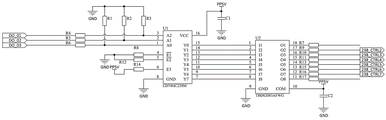
FIG. 7 is a schematic circuit diagram of the on-off control module;
FIG. 8 is a circuit schematic of the excitation source control module and the IO interface module;
FIG. 9 is a circuit schematic of the power module;
FIG. 10 is a schematic of a test connection of the present invention;
FIG. 11 is a schematic diagram of the connection of the test electrical parameter of the present invention;
FIG. 12 is a schematic view of the connection of the test coil magnetic field orientation of the present invention;
fig. 13 is a distribution diagram of the output state of the hall sensor.
Detailed Description
As shown in fig. 1 to 12, in the present embodiment, the present invention includes a TAG module 1, a channel switching module 2, and three sets of measuring modules 3 connected to a computer device, an input end of the channel switching module is connected to the TAG module 1, the three sets of measuring modules 3 are correspondingly connected to three sets of output ends of the channel switching module, each measuring module 3 includes two pairs of probe sets and a hall sensor U600 disposed on a carrier tool, the carrier tools of the three sets of measuring modules 3 are respectively adapted to three different lens module control coils, the two pairs of probe sets are respectively connected to an HP (hpot) port, an LP (lpot) port, an hc (hcur) port, and an lc (lcur) port of the TAG module 1 through the channel switching module 2, and the hall sensor U600 is connected to the HP port and the LP port of the TAG module 1.
In this embodiment, the hall sensor U600 adopts a bipolar south-north pole analog output hall effect sensing chip DRV5053 of TI as a sensor for determining the polarity of an air core coil, and outputs a voltage range: 0.2V to 1.8V, B = 0mT, OUT =1V, B > 0mT when S pole is close to the Hall sensor U600, and B < 0mT when N pole is close to the Hall sensor U600. When a current is applied to the coil to be tested, the winding direction corresponding to the coil will generate a magnetic field of south pole S and north pole N, the hall sensor U600 close to the coil will induce magnetism and output strength according to the magnetic field of the coil, and the output state is shown in a distribution diagram of fig. 13, where VQ =1V, the signal output by the hall sensor U600 is input to the HP port and the LP port of the TAG module 1 in the form of analog level, and the ADC circuit in the TAG module 1 reads the signal and performs analysis processing.
In this embodiment, the TAG module 1 is a simplified module of an LCR meter, and the test principle is the same as that of the LCR meter, as shown in fig. 2, the TAG module 1 includes an FPGA module, a GPIO module, a signal source module, an amplification module, a balanced impedance module, a multi-way selection switch module, and a high-speed ADC module, which are arranged on a board card structure, the FPGA module is configured to transfer and process data of each module, and the GPIO module is connected between the FPGA module and an IO interface module to perform expansion of an IO port and signal transmission; the signal source module is communicated with the FPGA module and generates a signal source to the HC port, wherein the signal source is a voltage source or a current source, and a coupling switch is also arranged between the signal source module and the HC port; the input end of the amplification module is connected with the LP port and the balanced impedance module to compare a read-back signal with an excitation loop signal and feed back an error to the FPGA module, and the output end of the amplification module is connected with the FPGA module; the balanced impedance module comprises a plurality of high-precision resistors with different resistance values and is used for carrying out attenuation adjustment on excitation source signals, the output end of the balanced impedance module is connected with the FPGA module, and the input end of the balanced impedance module is connected with the LC port; the output ends of the HP port, the LP port, the LC port and the balanced impedance module are respectively connected to a plurality of input ends of the multi-path selection switch module, and the high-speed ADC module converts path signals switched by the multi-path selection switch module and feeds the path signals back to the FPGA module.
The low-frequency (100KHz) measurement precision of the TAG module 1 is 0.1%; measurement frequencies up to 2 MHz; the programmable alternating current excitation signal can reach 4 Vpp; various impedance parameters such as inductance, capacitance, resistance, phase and the like can be measured; supporting a voltage, current Automatic Level Control (ALC) function; the remote control of an RJ45 Ethernet interface is supported;
in this embodiment, the channel switching module 2 includes four sets of input ports Hpot \ Lpot \ Hcur \ Lcur and three sets of switching relay modules, the four sets of input ports Hpot \ Lpot \ Hcur \ Lcur are respectively connected to the HC port, LC port, HP port and LP port of the TAG module 1, the input ends of the three sets of switching relay modules are all connected to the four sets of input ports Hpot \ Lpot \ Hcur \ Lcur, the switching relay modules include a first relay Coil700\ Coil701\ Coil702, a second relay Coil1_ POT Coil2_ Coil3_ POT, a third relay Coil1_ Coil2_ Coil703, a fourth relay Coil704 and a first connector Coil705, a first connector Coil AB, a second relay Coil701 _ fail \ Coil703 _ Coil703 and a set of corresponding to the first relay Coil700\ Coil1, LP 3 and LP relay 700 _ Coil 31, and the first connector Coil AB, the second relay Coil 31 _ Coil 200, the second relay Coil 200 _ Coil 200 is connected to the second terminal Coil 493 \ Coil703\ Coil 200, the first relay port of the TAG module 700\ LC port 31, and the first connector, the first switching relay somewhere ep 31 _ Coil 31, the group of the first relay, the second relay, the group of the switching relay module 700 Coil 31, the switching relay, the first connector, the second relay, the switching relay, the second relay, the third relay, the relay, and the relay, the relay 31, the relay, and the relay, the relay 31, the relay, and the relay, the relay 31, the relay, and the relay, and the relay, the, a first group of connection terminals of the third relay Coil1_ Coil2_ Coil3_ Coil are correspondingly connected with an HC port and an LC port of the TAG module 1, a second group of connection terminals of the second relay Coil1_ POT \ Coil2_ POT \ Coil3_ POT and the third relay Coil1_ Coil2_ Coil3_ Coil are correspondingly connected with an HC Coil port, an HP Coil port, an LP Coil port and an LC Coil port of the measurement module 3 on the first connector Coil1AB Coil2 AB/Coil 3AB, a second group of connection terminals of the first relay Coil 701/Coil 702 are connected with a power supply Coil _ OUT of a SENSE Coil AB of the first connector Coil1AB Coil2AB and a feedback signal Coil OUT of the second group of connection terminals of the first relay Coil703 _ Coil704 and the second group of feedback relay Coil703 _ Coil703 and the feedback Coil sensor of the fourth relay Coil703 _ Coil 5827 _ Coil703, and the feedback signal Coil sensor of the second group Coil703 _ Coil 200 _ Coil 583, and a second group of wiring terminals of the fourth relay Coil703\ Coil704\ Coil705 are connected to the first connector Coil1AB \ Coil2AB \ Coil3 AB. The first relay Coil700\ Coil701\ Coil702, the second relay Coil1_ POT \ Coil2_ POT \ Coil3_ POT, the third relay Coil1_ CURR \ Coil2_ CURR \ Coil3_ CURR and the fourth relay Coil703\ Coil704\ Coil705 are all mechanical relays with the model number of AGQ200A 4H.
In this embodiment, the measurement module 3 further includes a second connector J1\ J2 mated with the first connector Coil1AB \ Coil2AB \ Coil3AB, an output port of the hall sensor U600 is connected to the DRV5053_ OUT port of the second connector J1\ J2, a ground terminal of the hall sensor U600 is connected to the DRV5053 GND port of the second connector J1\ J2, when the two connectors J1\ J2 are mated and connected to the first connector Coil1AB \ Coil2AB \ Coil3AB, the DRV5053_ OUT port is conducted with the SENSE _ OUT port, and the DRV5053 port is conducted with the SENSE _ GND port.
In this embodiment, the channel switching module 2 further includes an on-off control module and a plurality of groups of excitation source control modules, the on-off control module includes an encoder U1 with a model of CD74HC238M and a transistor array unit U2 with a model of TBD62083AFWG, an input end of the encoder U1 is connected to an IO port of the TAG module 1, an output end of the encoder U1 is connected to an input end of the transistor array unit U2, an output end of the transistor array unit U2 is correspondingly connected to coils of the first relay Coil700\ Coil701\ Coil702, the second relay Coil1_ POT \ Coil2_ POT \ Coil3_ POT and the fourth relay Coil703\ Coil704\ Coil705 of each group of the switching relay modules, the excitation source control module includes a field-effect tube Q700\ Q701\ Q702, a gate of the field-effect tube Q700\ Q701Q 702 is connected to the IO port of the TAG module 701\ Q701, and a source of the TAG Q701\ Q701 is connected to the IO port 701 of the ground, the drain of the field effect transistor Q700\ Q701\ Q702 is correspondingly connected to the coils of the third relay Coil1_ CURR \ Coil2_ CURR \ Coil3_ CURR of the group of switching relay modules. The excitation source control module further comprises an LED indicator light, the cathode of the LED indicator light is connected with the drain electrode of the field effect tube Q700\ Q701\ Q702, the anode of the LED indicator light is connected with a power supply, and the LED indicator light is used for showing whether the corresponding test module 3 excitation source loop is conducted or not.
In this embodiment, the channel switching module 2 further includes an IO interface module cooperatively connected with an upper computer, and an output end of the IO interface module is connected to the on-off control module and the plurality of sets of excitation source control modules.
In this embodiment, the system for testing performance of a lens module coil further includes a power module, where the power module is configured to perform isolation filtering on an input power and convert a 12V input voltage into a 5V working voltage, and output the working voltage to each module.
The lens module coil performance test detection system further comprises the following specific test steps:
step S1, firstly, loading a coil to be tested on the carrier tool through a manual or carrying mechanism, and enabling the two pairs of probe sets to be respectively contacted with the upper end surface and the lower end surface of two leads led out from the coil to be tested, thereby forming a four-wire connection state;
step S2, as shown in fig. 11, the channel switching module 2 connects a group of the measurement module 3 loaded with a Coil to be measured with the TAG module 1, and at this time, the TAG module 1 outputs a corresponding control signal from an IO port according to a control instruction of a computer device, and controls the corresponding field-effect transistor Q700\ Q701\ Q702 to be connected, so that the corresponding third relay Coil1_ CURR \ Coil2_ CURR \ Coil3_ CURR Coil is powered on and switched on, thereby connecting the HC port and the LC port of the TAG module 1 with a lower probe group in the measurement module 3, and connecting an excitation source loop; the encoder U1 outputs a corresponding state after receiving a control signal to enable the transistor array unit U2 to adjust the current state of each channel, further controls the corresponding Coil loop 1_ POT \ Coil2_ POT \ Coil3_ POT Coil to be powered on and switched on, connects the HP port and the LP port of the TAG module 1 with the upper probe set in the measurement module 3, and switches on the measurement feedback loop; step S3, the TAG module 1 provides excitation source signals for a coil to be tested through an HC port and an LC port, and the TAG module 1 reads signals of the coil to be tested through an HP port and an LP port;
step S4, the TAG module 1 processes and transforms the read signals and then calculates the inductance and the impedance;
specifically, the TAG module 1 performs DFT discrete fourier transform on the collected signal to obtain a complex impedance expression Zx = a + bi, where complex impedance calculation formulas of an ideal inductance form L and an ideal resistance R are as follows:
the expression of the ideal inductance form L is ;
The expression of the ideal resistance form L is ;
Wherein the imaginary number of the ideal resistance is 0, and the real parts of the ideal capacitance and inductance are 0. For impedances Z with real and imaginary parts other than 0, this can be equivalent to a combination of resistance and capacitance/inductance.
There are 4 equivalent combination models, namely a capacitor and a resistor in series (Cs-Rs), an inductor and a resistor in series (Ls-Rs), a capacitor and a parallel resistor (Cp-Rp), and an inductor and a parallel resistor (Lp-Rp). If the impedance Zx = a + bi, the calculation of the resistance is different from the calculation of the capacitance/inductance, and an equivalent model is adopted in the invention as the series connection (Ls-Rs) of the inductance and the resistance, and the following expression is shown:


step S5, after the electrical parameter measurement is completed, as shown in fig. 12, the channel switching module 2 disconnects the pair of probe sets connected to the HP port and the LP port, and connects the hall sensor U600 to the HP port and the LP port of the TAG module 1;
step S6, the TAG module 1 provides a driving source signal for a coil to be tested through an HC port and an LC port, and the TAG module 1 reads an output signal of the Hall sensor U600 through an HP port and an LP port;
and step S7, the TAG module 1 judges the magnetic field polarity direction of the coil according to the excitation source signal and the phase state of the output signal of the Hall sensor U600.
Specifically, the TAG module 1 adopts a complex impedance measuring method, the TAG module 1 generates an alternating current excitation signal source of 10KHz and 20mA current, the HC port and the LC port are controlled by a relay to be sent to the measured coil L, when the dotted end of the measured coil L is fed with forward current, the current and voltage phases of the hall sensor U600 are the same as the current and voltage phases of the measured coil, the HP port and the LP port of the TAG module 1 measure the signal at the hall sensor output end to obtain complex impedance Zx = a + bj, and the imaginary part inductance value is positive at this time.
If the measured winding directions of the coils are opposite, or the directions of the coils are reversed during loading, the direction of the current of the HC port flows from the synonym end of the measured coil L, the south and north pole directions of the magnetic field of the coils will change, the phase difference of the current and the voltage of the Hall sensor U600 and the current and the voltage of the measured coil L is 180 degrees, the HP port and the LP port of the TAG module 1 measure the signals of the Hall sensor output end, complex impedance Zx = a-bj is obtained, and the inductance value of the imaginary part is a negative number at the moment.
Therefore, the winding direction of the coil is opposite.
Claims (4)
1. The utility model provides a lens module coil capability test detecting system which characterized in that: the device comprises a TAG module (1), a channel switching module (2) and at least three groups of measuring modules (3), wherein the input end of the channel switching module is connected with the TAG module (1), the measuring modules (3) are correspondingly connected with one group of output ends of the channel switching module, each measuring module (3) comprises two pairs of probe sets and a Hall sensor, the two pairs of probe sets are arranged on a carrier tool, the two pairs of probe sets are respectively connected to an HP port, an LP port, an HC port and an LC port of the TAG module (1), and the Hall sensor is connected to the HP port and the LP port of the TAG module (1); the lens module coil performance test detection system further comprises the following specific test steps:
step S1, firstly, loading a coil to be tested on the carrier tool through a manual or carrying mechanism, and enabling the two pairs of probe sets to be respectively contacted with the upper end face and the lower end face of two leads led out by the coil to be tested to form four-wire connection;
step S2, the channel switching module (2) conducts the measuring module (3) loaded with the coil to be measured and the TAG module (1);
s3, the TAG module (1) provides a driving source signal for a coil to be detected through an HC port and an LC port, and the TAG module (1) reads a signal of the coil to be detected through an HP port and an LP port;
step S4, the TAG module (1) processes and transforms the read signals and then calculates the inductance and the impedance;
step S5, after the electrical parameter measurement is completed, the channel switching module (2) disconnects a pair of probe sets connected with an HP port and an LP port, and the Hall sensor is connected to the HP port and the LP port of the TAG module (1);
step S6, the TAG module (1) provides a driving source signal for a coil to be tested through an HC port and an LC port, and the TAG module (1) reads an output signal of the Hall sensor through an HP port and an LP port;
and step S7, the TAG module (1) judges the magnetic field polarity direction of the coil according to the excitation source signal and the phase state of the output signal of the Hall sensor.
2. The system for testing performance of lens module coil according to claim 1, wherein: the channel switching module (2) comprises four groups of input ports and a plurality of groups of switching relay modules, the four groups of input ports are respectively connected to an HC port, an LC port, an HP port and an LP port of the TAG module (1), the input ends of the switching relay modules are respectively connected with the four groups of input ports, the switching relay modules comprise a first relay, a second relay, a third relay, a fourth relay and a first connector, first group wiring terminals of the first relay and the second relay are correspondingly connected with the HP port and the LP port of the TAG module (1), first group wiring terminals of the third relay are correspondingly connected with the HC port and the LC port of the TAG module (1), second group wiring terminals of the second relay and the third relay are correspondingly connected with the port of the measuring module (3) on the first connector, the second group of wiring terminals of the first relay is connected with the signal feedback port of the first connector, the signal feedback port is connected with the Hall sensor, the first group of wiring terminals of the fourth relay is connected with the power supply and the second group of wiring terminals of the third relay, and the second group of wiring terminals of the fourth relay is connected to the first connector.
3. The system for testing performance of lens module coil according to claim 2, wherein: the measuring module (3) further comprises a second connector matched with the first connector, and the output port of the Hall sensor is connected with the signal feedback port of the first connector through the second connector.
4. The system for testing performance of lens module coil according to claim 2, wherein: the channel switching module (2) further comprises an on-off control module and a plurality of groups of excitation source control modules, the on-off control module comprises an encoder and a transistor array unit, the input end of the encoder is connected with the IO port of the TAG module (1), the output end of the encoder is connected with the input end of the transistor array unit, the output end of the transistor array unit is correspondingly connected to each group of the first relay, the second relay and the coil of the fourth relay of the switching relay module, the excitation source control module comprises a field effect tube, the grid of the field effect tube is connected with the IO port of the TAG module (1), the source electrode of the field effect tube is grounded, and the drain electrode of the field effect tube is correspondingly connected to one group of the coil of the third relay of the switching relay module.
Priority Applications (1)
| Application Number | Priority Date | Filing Date | Title |
|---|---|---|---|
| CN202210562364.3A CN115032454B (en) | 2022-05-23 | 2022-05-23 | Lens module coil performance test detecting system |
Applications Claiming Priority (1)
| Application Number | Priority Date | Filing Date | Title |
|---|---|---|---|
| CN202210562364.3A CN115032454B (en) | 2022-05-23 | 2022-05-23 | Lens module coil performance test detecting system |
Publications (2)
| Publication Number | Publication Date |
|---|---|
| CN115032454A true CN115032454A (en) | 2022-09-09 |
| CN115032454B CN115032454B (en) | 2024-10-11 |
Family
ID=83120894
Family Applications (1)
| Application Number | Title | Priority Date | Filing Date |
|---|---|---|---|
| CN202210562364.3A Active CN115032454B (en) | 2022-05-23 | 2022-05-23 | Lens module coil performance test detecting system |
Country Status (1)
| Country | Link |
|---|---|
| CN (1) | CN115032454B (en) |
Citations (7)
| Publication number | Priority date | Publication date | Assignee | Title |
|---|---|---|---|---|
| DE102004007369A1 (en) * | 2004-02-16 | 2005-09-08 | Pepperl + Fuchs Gmbh | Circuit arrangement for detecting earthing has coil in power feed line so load is in series with coil, measurement coil inductively coupled to coil and connected to voltage detector |
| CN201203938Y (en) * | 2008-01-25 | 2009-03-04 | 陕西永辉测控技术有限公司 | Cable wireless test system |
| CN103454554A (en) * | 2013-08-30 | 2013-12-18 | 广东威恒输变电工程有限公司 | Polarity tester for current transformer |
| CN110266569A (en) * | 2019-05-22 | 2019-09-20 | 三明学院 | An IO-LINK port expansion device and method |
| CN110837040A (en) * | 2019-12-13 | 2020-02-25 | 珠海市运泰利自动化设备有限公司 | Charger mainboard test equipment for simulating wireless charging of Qi standard by using real coil |
| US20210173019A1 (en) * | 2019-12-06 | 2021-06-10 | Samsung Electro-Mechanics Co., Ltd. | Circuit for monitoring voltage of output terminal of hall sensor and circuit for supporting lens module actuating controller |
| CN113341246A (en) * | 2021-05-24 | 2021-09-03 | 国网陕西省电力公司西安供电公司 | Arc suppression coil testing device and method based on capacitance calibration |
-
2022
- 2022-05-23 CN CN202210562364.3A patent/CN115032454B/en active Active
Patent Citations (7)
| Publication number | Priority date | Publication date | Assignee | Title |
|---|---|---|---|---|
| DE102004007369A1 (en) * | 2004-02-16 | 2005-09-08 | Pepperl + Fuchs Gmbh | Circuit arrangement for detecting earthing has coil in power feed line so load is in series with coil, measurement coil inductively coupled to coil and connected to voltage detector |
| CN201203938Y (en) * | 2008-01-25 | 2009-03-04 | 陕西永辉测控技术有限公司 | Cable wireless test system |
| CN103454554A (en) * | 2013-08-30 | 2013-12-18 | 广东威恒输变电工程有限公司 | Polarity tester for current transformer |
| CN110266569A (en) * | 2019-05-22 | 2019-09-20 | 三明学院 | An IO-LINK port expansion device and method |
| US20210173019A1 (en) * | 2019-12-06 | 2021-06-10 | Samsung Electro-Mechanics Co., Ltd. | Circuit for monitoring voltage of output terminal of hall sensor and circuit for supporting lens module actuating controller |
| CN110837040A (en) * | 2019-12-13 | 2020-02-25 | 珠海市运泰利自动化设备有限公司 | Charger mainboard test equipment for simulating wireless charging of Qi standard by using real coil |
| CN113341246A (en) * | 2021-05-24 | 2021-09-03 | 国网陕西省电力公司西安供电公司 | Arc suppression coil testing device and method based on capacitance calibration |
Non-Patent Citations (2)
| Title |
|---|
| 张泽宇: "导航系统中电涡流效应的实际应用", 自动化仪表, no. 08, 20 August 2017 (2017-08-20), pages 82 - 86 * |
| 邓龙龙等: "基于自由轴法的电感测量电路设计", 电子测量技术, no. 11, 15 November 2013 (2013-11-15), pages 12 - 16 * |
Also Published As
| Publication number | Publication date |
|---|---|
| CN115032454B (en) | 2024-10-11 |
Similar Documents
| Publication | Publication Date | Title |
|---|---|---|
| CN105005016B (en) | A kind of three-phase electric energy meter on-site check system and its method | |
| CN106980297B (en) | Multichannel pressure data acquisition circuit and multichannel pressure data acquisition system | |
| CN201096867Y (en) | Multi-function tester for measuring semiconductor silicon material P/N and resistance rate | |
| CN206649051U (en) | Digital acceleration measurement apparatus with constant current source power supply | |
| CN201497780U (en) | Rapid cyclic-detection device for two-wire industrial instruments | |
| CN106707213B (en) | A kind of digital integrated electronic circuit standard sample of photo | |
| CN107015556A (en) | A kind of bus solid-state power controller test device | |
| CN115032454B (en) | Lens module coil performance test detecting system | |
| US7016792B2 (en) | Transducer comprising a connected data memory | |
| CN111693922A (en) | Automatic calibration system of impedance tester | |
| CN2874514Y (en) | Full automatic resistance corrector | |
| CN111123073B (en) | A fast self-checking device for hardware board | |
| CN111141406B (en) | PT100 temperature measurement system and temperature measurement method | |
| CN118625203A (en) | A calibration module and method for calibrating a multi-channel output power supply of a signal detector | |
| CN115166369B (en) | A method for testing the output impedance of a two-wire IEPE sensor | |
| EP4354152A1 (en) | Power calibration adapter, measurement application system, method | |
| CN217112681U (en) | Ammeter circuit compensation module | |
| CN109061524A (en) | Power supply test circuit and method | |
| CN101206252A (en) | Digital multimeter measuring system and method | |
| CN211123024U (en) | PCB branch current detection device and PCB detection system | |
| CN210071934U (en) | A four-channel leakage current sensor | |
| CN217954573U (en) | Measurement circuit system suitable for camera inductance coil | |
| CN117031100B (en) | A front-end circuit of a multimeter and the multimeter itself. | |
| CN220626600U (en) | Structure for detecting connection and conduction of stepping motor | |
| CN208350114U (en) | A kind of measurement verification system |
Legal Events
| Date | Code | Title | Description |
|---|---|---|---|
| PB01 | Publication | ||
| PB01 | Publication | ||
| SE01 | Entry into force of request for substantive examination | ||
| SE01 | Entry into force of request for substantive examination | ||
| GR01 | Patent grant | ||
| GR01 | Patent grant |