CN115026044A - Separation cleaning equipment that glass cleaner used - Google Patents
Separation cleaning equipment that glass cleaner used Download PDFInfo
- Publication number
- CN115026044A CN115026044A CN202210947654.XA CN202210947654A CN115026044A CN 115026044 A CN115026044 A CN 115026044A CN 202210947654 A CN202210947654 A CN 202210947654A CN 115026044 A CN115026044 A CN 115026044A
- Authority
- CN
- China
- Prior art keywords
- box body
- suction
- box
- cleaning agent
- inner cavity
- Prior art date
- Legal status (The legal status is an assumption and is not a legal conclusion. Google has not performed a legal analysis and makes no representation as to the accuracy of the status listed.)
- Granted
Links
- 239000011521 glass Substances 0.000 title claims abstract description 72
- 238000004140 cleaning Methods 0.000 title claims abstract description 69
- 238000000926 separation method Methods 0.000 title claims abstract description 27
- 239000012459 cleaning agent Substances 0.000 claims abstract description 56
- 239000007788 liquid Substances 0.000 claims abstract description 52
- 238000001914 filtration Methods 0.000 claims abstract description 51
- 229920000742 Cotton Polymers 0.000 claims abstract description 48
- 239000012535 impurity Substances 0.000 claims abstract description 44
- 238000001179 sorption measurement Methods 0.000 claims description 15
- 239000007921 spray Substances 0.000 claims description 15
- 239000008187 granular material Substances 0.000 claims description 14
- 239000012528 membrane Substances 0.000 claims description 13
- 230000007246 mechanism Effects 0.000 claims description 7
- 229910000831 Steel Inorganic materials 0.000 claims description 4
- 239000010959 steel Substances 0.000 claims description 4
- ZZUFCTLCJUWOSV-UHFFFAOYSA-N furosemide Chemical group C1=C(Cl)C(S(=O)(=O)N)=CC(C(O)=O)=C1NCC1=CC=CO1 ZZUFCTLCJUWOSV-UHFFFAOYSA-N 0.000 claims description 2
- 210000001503 joint Anatomy 0.000 claims description 2
- 238000005406 washing Methods 0.000 claims 4
- 238000004378 air conditioning Methods 0.000 claims 1
- 238000010030 laminating Methods 0.000 claims 1
- 239000002245 particle Substances 0.000 abstract description 23
- 230000000694 effects Effects 0.000 abstract description 11
- 239000011148 porous material Substances 0.000 abstract 1
- 239000002699 waste material Substances 0.000 description 44
- 238000003825 pressing Methods 0.000 description 17
- 238000003754 machining Methods 0.000 description 13
- 238000012545 processing Methods 0.000 description 11
- 238000005457 optimization Methods 0.000 description 5
- 230000009471 action Effects 0.000 description 4
- 239000010808 liquid waste Substances 0.000 description 3
- 239000011859 microparticle Substances 0.000 description 3
- 238000004064 recycling Methods 0.000 description 3
- 230000000717 retained effect Effects 0.000 description 3
- 239000010865 sewage Substances 0.000 description 3
- 238000003756 stirring Methods 0.000 description 3
- 238000005520 cutting process Methods 0.000 description 2
- 230000005389 magnetism Effects 0.000 description 2
- 238000012423 maintenance Methods 0.000 description 2
- 238000012986 modification Methods 0.000 description 2
- 230000004048 modification Effects 0.000 description 2
- 230000009467 reduction Effects 0.000 description 2
- 238000007789 sealing Methods 0.000 description 2
- 238000005507 spraying Methods 0.000 description 2
- XLYOFNOQVPJJNP-UHFFFAOYSA-N water Substances O XLYOFNOQVPJJNP-UHFFFAOYSA-N 0.000 description 2
- 238000010521 absorption reaction Methods 0.000 description 1
- 230000009286 beneficial effect Effects 0.000 description 1
- 230000003139 buffering effect Effects 0.000 description 1
- 238000004891 communication Methods 0.000 description 1
- 238000013461 design Methods 0.000 description 1
- 238000009776 industrial production Methods 0.000 description 1
- 238000009434 installation Methods 0.000 description 1
- 230000007774 longterm Effects 0.000 description 1
- 238000000034 method Methods 0.000 description 1
- 230000000149 penetrating effect Effects 0.000 description 1
- 230000008569 process Effects 0.000 description 1
- 238000005086 pumping Methods 0.000 description 1
- 238000005096 rolling process Methods 0.000 description 1
- 238000006748 scratching Methods 0.000 description 1
- 230000002393 scratching effect Effects 0.000 description 1
- 238000003466 welding Methods 0.000 description 1
Images


Classifications
-
- B—PERFORMING OPERATIONS; TRANSPORTING
- B08—CLEANING
- B08B—CLEANING IN GENERAL; PREVENTION OF FOULING IN GENERAL
- B08B3/00—Cleaning by methods involving the use or presence of liquid or steam
- B08B3/02—Cleaning by the force of jets or sprays
-
- B—PERFORMING OPERATIONS; TRANSPORTING
- B01—PHYSICAL OR CHEMICAL PROCESSES OR APPARATUS IN GENERAL
- B01D—SEPARATION
- B01D24/00—Filters comprising loose filtering material, i.e. filtering material without any binder between the individual particles or fibres thereof
- B01D24/02—Filters comprising loose filtering material, i.e. filtering material without any binder between the individual particles or fibres thereof with the filter bed stationary during the filtration
- B01D24/10—Filters comprising loose filtering material, i.e. filtering material without any binder between the individual particles or fibres thereof with the filter bed stationary during the filtration the filtering material being held in a closed container
- B01D24/16—Upward filtration
- B01D24/165—Upward filtration the filtering material being supported by pervious surfaces
-
- B—PERFORMING OPERATIONS; TRANSPORTING
- B01—PHYSICAL OR CHEMICAL PROCESSES OR APPARATUS IN GENERAL
- B01D—SEPARATION
- B01D24/00—Filters comprising loose filtering material, i.e. filtering material without any binder between the individual particles or fibres thereof
- B01D24/48—Filters comprising loose filtering material, i.e. filtering material without any binder between the individual particles or fibres thereof integrally combined with devices for controlling the filtration
- B01D24/4807—Handling the filter cake for purposes other than regenerating
- B01D24/4846—Retarding cake deposition on the filter during the filtration period, e.g. using stirrers
-
- B—PERFORMING OPERATIONS; TRANSPORTING
- B01—PHYSICAL OR CHEMICAL PROCESSES OR APPARATUS IN GENERAL
- B01D—SEPARATION
- B01D36/00—Filter circuits or combinations of filters with other separating devices
- B01D36/04—Combinations of filters with settling tanks
-
- B—PERFORMING OPERATIONS; TRANSPORTING
- B08—CLEANING
- B08B—CLEANING IN GENERAL; PREVENTION OF FOULING IN GENERAL
- B08B3/00—Cleaning by methods involving the use or presence of liquid or steam
- B08B3/04—Cleaning involving contact with liquid
- B08B3/10—Cleaning involving contact with liquid with additional treatment of the liquid or of the object being cleaned, e.g. by heat, by electricity or by vibration
- B08B3/14—Removing waste, e.g. labels, from cleaning liquid
Landscapes
- Chemical & Material Sciences (AREA)
- Chemical Kinetics & Catalysis (AREA)
- Cleaning In General (AREA)
Abstract
The invention relates to a separation cleaning device for a glass cleaning agent. The invention belongs to the technical field of separation and cleaning equipment; the separation cleaning equipment comprises a box body, wherein a filtering component used for filtering particle impurities in liquid is arranged in the box body, the filtering component comprises a sucker, a filtering cotton block and an inner cavity, the sucker is of a disc-shaped structure, the separation cleaning equipment is suitable for separation cleaning of a glass cleaning agent, the glass cleaning agent can be recycled after the particle impurities in the glass cleaning agent are filtered, and in order to keep the filtering effect of the filtering cotton block on the glass cleaning agent, a pressurized cleaning component is arranged in the box body, so that the filtering effect of the filtering cotton block on the particle impurities is kept, and the phenomenon that the particle impurities are blocked in pores on the surface of the filtering cotton block cannot occur.
Description
Technical Field
The invention belongs to the technical field of separation cleaning equipment, and particularly relates to separation cleaning equipment for a glass cleaning agent.
Background
The glass cleaning agent is used for cleaning oil stains on the surface of glass, and the glass cleaning agent has wide application in cleaning in family life and industrial production.
The glass cleaning agent can deposit more and more particle impurities in the long-term use process, the particle impurities easily cause the scratching phenomenon to a workpiece to be cleaned when the glass cleaning agent is recycled, and the filtering effect is poor when the glass cleaning agent is recycled. Therefore, a separate cleaning device for glass cleaning agents is proposed to solve the above drawbacks.
Disclosure of Invention
The invention aims to solve the problems and provide a separation and cleaning device which is simple in structure and reasonable in design.
The invention realizes the purpose through the following technical scheme:
the utility model provides a separation cleaning equipment that glass cleaner used, includes the box, the inside of box is provided with the filtering component who is arranged in filtering liquid granule impurity, and filtering component includes sucking disc, filtering cotton piece and interior cavity, the sucking disc is discoid structure, and a week of sucking disc is provided with the multiunit and runs through the inside and outside suction hole of sucking disc simultaneously, the lower extreme of sucking disc is provided with the opening, and the opening position is connected with the annular seal plate through screw-thread fit, the lower fixed surface of annular seal plate is provided with the second magnetic adsorption board, the upper end middle part of sucking disc and the inside intercommunication of the lower extreme of box, interior cavity fixed mounting is in the inside of box, filtering cotton piece sets up in the below of interior cavity, filters cotton piece and separates into upper chamber, the lower chamber that distributes from top to bottom with the inside of box, be provided with power unit on the interior cavity, produce suction through power unit, so that the external liquid is filtered sequentially through the sucking disc, the filtering cotton block and the inner cavity.
As a further optimized scheme of the invention, a second hose section is fixedly arranged in the middle of the upper end of the suction cup, a suction pipeline is fixedly arranged at the lower end of the box body, the suction pipeline is butted with the end part of the second hose section, the suction pipeline is communicated with the lower chamber, and the inside of the suction cup is communicated with the second hose section.
The glass cleaning agent box is suitable for separating and cleaning glass cleaning agents, particle impurities in the glass cleaning agents can be filtered, and then the glass cleaning agents can be recycled, specifically, the box body is installed on machine tool machining equipment, the cleaning spray head is installed on the surface of the machine tool machining equipment and is aligned to one side facing a workpiece machining position, the sucker is installed at the bottom position of a machining surface of the machine tool machining equipment and is used for collecting waste liquid, when the glass cleaning agent box works, the glass cleaning agents are stored in the box body, when a servo motor is started, the moving blades are driven to rotate through the power shaft, suction force is generated when the blades rotate, the glass cleaning agents in the box body sequentially pass through the upper suction pipeline, the inner cavity, the protruding shell and the first hose section and then are sprayed to the workpiece machining position from the position of the cleaning spray head, and the purpose of cleaning workpieces by using the glass cleaning agents is achieved.
The glass cleaner washes the granule impurity that the work piece surface contains after wasing the work piece and removes, granule impurity mixes in the glass cleaner and assembles the bottom along the machined surface on the machine tool machining equipment, the position that the waste liquid assembles is placed to the sucking disc, start negative pressure fan, negative pressure fan takes out the negative pressure to the box inside, at this moment, the waste liquid accessible is inhaled the hole and is inhaled in the second hose section, the glass cleaner who is inhaled in the second hose section passes through the suction pipeline of second hose section upper end and gets into cavity down, because the inside of box is inhaled by second hose section from the bottom up to the glass cleaner, the large granule impurity that contains in the glass cleaner is difficult upwards to carry to the box in, the purpose of the separation of large granule impurity in the waste liquid in the time of having realized being about to when the suction removes the waste liquid.
The waste liquid is retained in the lower cavity when being sucked into the box body, the waste liquid in the lower cavity seeps from the upper part of the filter cotton block after being increased continuously, most particle impurities in the waste liquid are filtered by natural filtration of the filter cotton block, most particle impurities are filtered in the lower cavity, the waste liquid overflowing the upper part of the filter cotton block is sucked into the inner cavity through the upper suction pipeline and the suction inlet connecting pipe in sequence under the action of suction generated by rotation of the blades, the waste liquid entering the inner cavity is sprayed out from the cleaning spray head for reuse after sequentially passing through the release groove, the matching pipeline, the hard connecting pipe and the first hose section, the purpose of recycling is achieved, in the equipment, the width of the release groove is larger than the diameter of the inner cavity, the waste liquid entering the release groove from the inner cavity is decelerated due to the increase of the flow surface, the decelerated waste liquid is filtered for the third time through the filter membrane, and the micro particle impurities in the waste liquid are filtered through the filter membrane, and the waste liquid can not cause impact damage to the filter membrane after being decelerated.
The machine tool machining apparatus described above is, for example, a chip cutting machine or the like.
As a further optimization scheme of the invention, the power mechanism comprises a servo motor, a power shaft and blades, the servo motor is connected to the outer surface of the box body through an angle steel plate, one end of the power shaft is connected to the end part of the servo motor, the other end of the power shaft movably extends into the inner part of the inner cavity, the blades are fixedly arranged at the end part of the power shaft, a convex shell is arranged on the inner cavity, the blades are arranged in the convex shell, one end of the inner cavity is provided with a suction inlet connecting pipe, the suction inlet connecting pipe is connected with an upper suction pipeline, the lower end of the upper suction pipeline corresponds to the upper surface of the filter cotton block, the upper suction pipeline is communicated with the inner part of the inner cavity, the other end of the inner cavity is provided with a matching pipeline, the matching pipeline is connected with a hard connecting pipe, the lower end of the hard connecting pipe is integrally provided with a first hose section, and the first hose section extends to the outer part of the box body, the first hose section is in communication with the interior of the inner cavity.
In the equipment, the second hose section and the first hose section are both reserved with enough length and can be arranged at proper positions according to requirements.
As a further optimization scheme of the invention, a release groove is arranged at the position where the matching pipeline is communicated with the inner cavity, the release groove is integrally arranged at the lower end of the inner cavity, and the bottom surface of the release groove is provided with a filter membrane in a fitting manner.
As a further optimized scheme of the invention, one end of the first hose section, which is far away from the inner cavity body, is fixedly provided with a cleaning spray head, the interior of the cleaning spray head is provided with an ejection hole, one end of the ejection hole penetrates through the side surface of the cleaning spray head, the other end of the ejection hole is communicated with the interior of the first hose section, the side surface of the cleaning spray head, which is far away from the end of the ejection hole, is fixedly provided with an air bag, and the surface of the air bag is fixedly provided with a first magnetic adsorption plate.
The first magnetic adsorption plate can be fixed on the surface of machine tool machining equipment in an adsorption mode, the air bag can deform elastically and has a certain buffering effect, and the phenomenon that a cleaning nozzle swings seriously due to the fact that the pressure of glass cleaning agents sprayed out of the spraying hole is too large is avoided.
As a further optimization scheme of the invention, one end of the inner cavity is integrally provided with a first connecting plate, the first connecting plate is fixed on the inner wall of the box body through a screw, the other end of the inner cavity is integrally provided with a second connecting plate, the second connecting plate is fixed on the inner wall of the box body through a screw, the middle part of the first connecting plate is integrally provided with a through hole, and the position of the power shaft penetrating through the inner cavity is connected with the inner wall of the through hole through a rolling bearing.
The detachable connection of interior cavity is in the inside of box, makes things convenient for dismouting and maintenance.
As a further optimization scheme of the invention, a pressurized cleaning assembly is arranged in the box body, the pressurized cleaning assembly comprises a cleaning spray head, a pressing plate, a spring and a guide rod, the guide rod is fixedly welded on the inner wall of the lower end of the box body, the pressing plate is slidably arranged on the guide rod, an upper limiting ring and a lower supporting ring are connected to the guide rod in a threaded fit manner, the upper limiting ring and the lower supporting ring are arranged up and down, the upper end of the spring is fixedly connected to the bottom surface of the pressing plate, the lower end of the spring is fixedly connected to the upper surface of the lower supporting ring, the lower supporting ring and the pressing plate are both positioned above the filtering cotton block, a second magnetic suction block is fixedly arranged on the surface of the pressing plate, a first magnetic block is fixedly arranged at the end part of a blade of the outer ring of the power shaft, and the first magnetic block and the second magnetic suction block repel each other.
In order to keep the filtering effect of the filtering cotton block on the glass cleaning agent, a pressed cleaning assembly is arranged in the box body, when the blade rotates, a first magnetic block at the end part of the blade does circular motion around a power shaft as an axis, at the moment, the first magnetic block circularly moves between a position far away from and a position close to a second magnetic attraction block, when the first magnetic block is close to the second magnetic attraction block, the first magnetic block and the second magnetic attraction block repel each other, at the moment, the second magnetic attraction block moves downwards to push the pressing plate to move downwards, when the first magnetic block is far away from the second magnetic attraction block, the second magnetic attraction block loses the repulsion force, the pressing plate is pushed to reset upwards by a spring, when the first magnetic block does circular motion, the pressing plate does up-and-down reciprocating motion to form the purpose of stirring the glass cleaning agent at the bottom of the upper cavity, and when the pressing plate rapidly moves downwards at a high speed, the glass cleaning agent is pushed to flow through the filtering cotton block, thereby playing the purpose of back flush filtration cotton piece, having kept the filter effect of filtration cotton piece to granule impurity, the phenomenon of granule impurity jam in filtration cotton piece surface hole can not appear.
As a further optimized scheme of the invention, the bottom of the box body is fixedly provided with supporting legs.
The supporting legs are used for supporting the box body, and a suction pipeline and a sewage discharge pipe are conveniently arranged at the bottom of the box body.
As a further optimized scheme of the invention, a drain pipe is arranged at the bottom of the box body, an electromagnetic valve is arranged on the drain pipe, and the upper end of the drain pipe is communicated with the interior of the lower cavity.
The particle impurities collected in the lower chamber can be discharged through the drain pipe, and the particle impurities in the release groove can be discharged from a cleaning door on the side surface of the release groove, wherein the cleaning door is a common cleaning opening structure and is not shown in the figure.
The lower end of the sucker is also provided with a second magnetic adsorption plate which can be fixed on the surface of the machine tool machining equipment in an adsorption manner, so that the sucker is convenient to mount and use.
As a further optimization scheme of the invention, a negative pressure fan is fixedly arranged on the inner wall of the upper end of the box body, a first air pipe communicated with the outside of the box body is arranged at the upper end of the negative pressure fan, and a second air pipe communicated with the upper cavity is arranged at the lower end of the negative pressure fan.
The negative pressure suction fan reduces kinetic energy for absorbing waste liquid in a negative pressure suction mode in the box body, the kinetic energy for loss is small when air in the box body is sucked out, the external waste liquid is pressed into the box body from the suction disc under the action of negative pressure generated in the box body, and water at a low position can be conveyed into the box body at a high position by combining the principle of negative pressure suction, so that the kinetic energy for directly sucking the waste liquid into the box body is saved.
The invention has the beneficial effects that: the invention relates to a separation cleaning device for a glass cleaning agent, which comprises a box body, wherein a filtering component for filtering particle impurities in liquid is arranged in the box body, the filtering component comprises a sucker, a filtering cotton block and an inner cavity body, the sucker is of a disc-shaped structure, the separation cleaning device is suitable for separation cleaning of the glass cleaning agent, the particle impurities in the glass cleaning agent can be filtered, and then the glass cleaning agent can be recycled The inner cavity, the protruding shell and the first hose section are sprayed to the workpiece processing position from the position of the cleaning spray head, so that the purpose of cleaning the workpiece by using a glass cleaning agent is realized;
according to the invention, after the workpiece is cleaned by the glass cleaning agent, particle impurities on the surface of the workpiece are washed away, the particle impurities are mixed in the glass cleaning agent and are gathered to the bottom along the processing surface of the machine tool processing equipment, the sucking disc is placed at the position where the waste liquid is gathered, the negative pressure fan is started, the negative pressure fan pumps negative pressure to the inside of the box body, at the moment, the waste liquid can be sucked into the second hose section through the suction hole, the glass cleaning agent sucked into the second hose section enters the lower chamber through the suction pipeline at the upper end of the second hose section, and as the glass cleaning agent is sucked into the box body from bottom to top through the second hose section, the large particle impurities contained in the glass cleaning agent are not easy to be conveyed upwards into the box body, so that the purpose of separating the large particle impurities in the waste liquid when the waste liquid is sucked is achieved.
In the invention, the waste liquid is retained in the lower chamber when being sucked into the box body, the waste liquid in the lower chamber continuously increases and then seeps out from the upper part of the filter cotton block, most particle impurities in the waste liquid are filtered by natural filtration of the filter cotton block, most particle impurities are filtered in the lower chamber, the waste liquid overflowing above the filter cotton block is sucked into the inner cavity body through the upper suction pipeline and the suction inlet connecting pipe sequentially under the suction action generated by the rotation of the blades, the waste liquid entering the inner cavity body passes through the release groove, the matching pipeline, the hard connecting pipe and the first hose section sequentially and is sprayed out from the cleaning spray head for reuse, the purpose of recycling is achieved, in the equipment, the width of the release groove is larger than the diameter of the inner cavity body, the waste liquid entering the release groove from the inner cavity body is decelerated due to the increase of the flow surface, and the decelerated waste liquid is filtered for the third time through the filter membrane, the filter membrane filters micro-particle impurities in the waste liquid, and the waste liquid cannot impact and damage the filter membrane after being decelerated;
in order to keep the filtering effect of the filtering cotton block on the glass cleaning agent, a pressed cleaning assembly is arranged in the box body, when the blade rotates, a first magnetic block at the end part of the blade does circular motion around a power shaft as an axis, at the moment, the first magnetic block circularly moves between a position far away from and a position close to a second magnetic attraction block, when the first magnetic block is close to the second magnetic attraction block, the first magnetic block and the second magnetic attraction block repel each other, at the moment, the second magnetic attraction block moves downwards to push the pressing plate to move downwards, when the first magnetic block is far away from the second magnetic attraction block, the second magnetic attraction block loses the repulsion force, the pressing plate is pushed to reset upwards by a spring, when the first magnetic block does circular motion, the pressing plate does up-and-down reciprocating motion to form the purpose of stirring the glass cleaning agent at the bottom of the upper cavity, and when the pressing plate rapidly moves downwards at a high speed, the glass cleaning agent is pushed to flow through the filtering cotton block, thereby playing the purpose of back flush filtration cotton piece, having kept the filter effect of filtration cotton piece to granule impurity, the phenomenon of granule impurity jam in filtration cotton piece surface hole can not appear.
Drawings
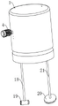
FIG. 1 is a schematic structural view of the present invention;
FIG. 2 is a cross-sectional view of the present invention;
FIG. 3 is a schematic view of the inner chamber structure of the present invention;
FIG. 4 is a schematic view of a filter plug according to the present invention;
FIG. 5 is a schematic view of a cleaning showerhead according to the present invention;
FIG. 6 is a schematic view of the structure of the sucking disc of the present invention;
fig. 7 is a schematic view of the blade structure of the present invention.
In the figure: 1. a box body; 2. angle steel plates; 3. a support leg; 4. a servo motor; 5. a blow-off pipe; 6. an electromagnetic valve; 7. a negative pressure fan; 8. a first air duct; 9. a second air duct; 10. an inner cavity; 11. a raised shell; 12. a power shaft; 13. a blade; 14. a first magnetic block; 15. filtering the cotton block; 16. an upper chamber; 17. a lower chamber; 18. a first hose segment; 19. cleaning the spray head; 20. a suction cup; 21. a second hose section; 22. a suction duct; 23. a guide bar; 24. a lower support ring; 25. a spring; 26. pressing a plate; 27. an upper suction duct; 28. an upper limiting ring; 29. a second magnetic attraction block; 30. a first connecting plate; 31. passing through the aperture; 32. a relief groove; 33. filtering the membrane; 34. fitting a pipeline; 35. a hard connecting pipe; 36. a second connecting plate; 37. a suction inlet connecting pipe; 38. an air bag; 39. a first magnetic adsorption plate; 40. a second magnetic adsorption plate; 41. an annular seal plate; 42. and (4) sucking holes.
Detailed Description
The present application will now be described in further detail with reference to the drawings, and it should be noted that the following detailed description is given for purposes of illustration only and should not be construed as limiting the scope of the present application, as these numerous insubstantial modifications and variations can be made by those skilled in the art based on the teachings of the present application.
As shown in fig. 1 to 7, a separation cleaning device for a glass cleaning agent comprises a box body 1, a filter assembly for filtering particle impurities in liquid is arranged inside the box body 1, the filter assembly comprises a suction cup 20, a filter cotton block 15 and an inner cavity 10, the suction cup 20 is of a disc-shaped structure, a plurality of groups of suction holes 42 which simultaneously penetrate through the inside and the outside of the suction cup 20 are arranged on the periphery of the suction cup 20, an opening is arranged at the lower end of the suction cup 20, an annular sealing plate 41 is connected to the opening through thread fit, a second magnetic adsorption plate 40 is fixedly arranged on the lower surface of the annular sealing plate 41, the middle part of the upper end of the suction cup 20 is communicated with the inside of the lower end of the box body 1, the inner cavity 10 is fixedly arranged inside the box body 1, the filter cotton block 15 is arranged below the inner cavity 10, the filter cotton block 15 divides the inside of the box body 1 into an upper cavity 16 and a lower cavity 17 which are distributed up and down, and a power mechanism is arranged on the inner cavity 10, the suction force is generated by the power mechanism, so that the external liquid passes through the suction cup 20, the filtering cotton block 15 and the inner cavity 10 in sequence for filtering.
A second hose section 21 is fixedly arranged in the middle of the upper end of the suction cup 20, a suction pipeline 22 is fixedly arranged at the lower end of the box body 1, the suction pipeline 22 is in butt joint with the end part of the second hose section 21, the suction pipeline 22 is communicated with the lower chamber 17, and the inside of the suction cup 20 is communicated with the second hose section 21.
The invention is suitable for separating and cleaning the glass cleaning agent, can filter particle impurities in the glass cleaning agent to ensure that the glass cleaning agent can be recycled, and particularly, the box body 1 is arranged on machine tool processing equipment, the cleaning spray nozzle 19 is arranged on the surface of the machine tool processing equipment, and the cleaning spray nozzle 19 is aligned to one side facing the processing position of the workpiece, the suction cup 20 is arranged at the bottom position for gathering waste liquid on the processing surface of the machine tool processing equipment, and when the machine tool processing equipment works, the box body 1 is stored with glass cleaning agent, the servo motor 4 drives the blade 13 to rotate through the power shaft 12 when being started, the blade 13 generates suction force when rotating, the glass cleaning agent in the box body 1 sequentially passes through the upper suction pipeline 27, the inner cavity 10, the protruding shell 11 and the first hose section 18 and then is sprayed to the workpiece processing position from the position of the cleaning spray head 19, and the purpose of cleaning the workpiece by using the glass cleaning agent is achieved.
The glass cleaner washes away the granule impurity that contains the workpiece surface after wasing the work piece, granule impurity mixes in the glass cleaner and assembles the bottom along the machined surface on the machine tool machining equipment, sucking disc 20 is placed in the position that the waste liquid assembles, start negative pressure fan 7, negative pressure fan 7 is to the inside negative pressure of taking out of box 1, at this moment, waste liquid accessible suction hole 42 is inhaled in the second hose section 21, the glass cleaner who is inhaled in the second hose section 21 passes through the suction pipe 22 of second hose section 21 upper end and gets into lower cavity 17, because the inside of box 1 is inhaled through second hose section 21 from the bottom up to the glass cleaner, the large granule impurity that contains in the glass cleaner is difficult for upwards carrying to in the box 1, the purpose of large granule impurity separation in the waste liquid when having realized removing the waste liquid soon.
The waste liquid is retained in the lower chamber 17 when being sucked into the box body 1, the waste liquid in the lower chamber 17 seeps out from the upper part of the filter cotton block 15 after increasing, most particle impurities in the waste liquid are filtered through natural filtration of the filter cotton block 15, most particle impurities are filtered in the lower chamber 17, the waste liquid overflowing the upper part of the filter cotton block 15 passes through the upper suction pipeline 27 and the suction inlet connecting pipe 37 in sequence under the suction effect generated when the blades 13 rotate, and is sucked into the inner cavity 10, the waste liquid entering the inner cavity 10 passes through the release groove 32, the matching pipeline 34, the hard connecting pipe 35 and the first hose section 18 in sequence and is sprayed out from the cleaning nozzle 19 again for utilization, the purpose of recycling is achieved, in the equipment, the width of the release groove 32 is larger than the diameter of the inner cavity 10, and the waste liquid entering the release groove 32 from the inner cavity 10 is decelerated due to the increase of the flow surface, the liquid waste after the speed reduction is filtered for the third time through the filter membrane 33, the filter membrane 33 filters micro-particle impurities in the liquid waste, and the liquid waste cannot cause impact damage to the filter membrane 33 after the speed reduction.
The machine tool machining apparatus described above is a chip cutting machine or the like.
The power mechanism comprises a servo motor 4, a power shaft 12 and blades 13, the servo motor 4 is connected to the outer surface of the box body 1 through an angle steel plate 2, one end of the power shaft 12 is connected to the end part of the servo motor 4, the other end of the power shaft movably extends into the inner part of the inner cavity 10, the blades 13 are fixedly installed at the end part of the power shaft 12, a protruding shell 11 is arranged on the inner cavity 10, the blades 13 are arranged in the protruding shell 11, one end of the inner cavity 10 is provided with a suction inlet connecting pipe 37, the suction inlet connecting pipe 37 is connected with an upper suction pipeline 27, the lower end of the upper suction pipeline 27 corresponds to the upper surface of the filter cotton block 15, the upper suction pipeline 27 is communicated with the inner part of the inner cavity 10, the other end of the inner cavity 10 is provided with a matching pipeline 34, the matching pipeline 34 is connected with a hard connecting pipe 35, a first hose section 18 is integrally arranged at the lower end of the hard connecting pipe 35, and the first hose section 18 extends to the outer part of the box body 1, the first hose section 18 communicates with the interior of the inner cavity 10.
In the apparatus, the second hose portion 21 and the first hose portion 18 are both left with sufficient length to be placed at appropriate locations as required.
The position of the matching pipeline 34 communicated with the inner cavity 10 is provided with a release groove 32, the release groove 32 is integrally arranged at the lower end of the inner cavity 10, and the bottom surface of the release groove 32 is provided with a filter membrane 33 in a fitting manner.
A cleaning nozzle 19 is fixedly arranged at one end of the first hose segment 18 far away from the inner cavity 10, an ejection hole is arranged in the cleaning nozzle 19, one end of the ejection hole penetrates through the side surface of the cleaning nozzle 19, the other end of the ejection hole is communicated with the inside of the first hose segment 18, an air bag 38 is fixedly arranged at the side surface of the cleaning nozzle 19 far away from the end of the ejection hole, and a first magnetic adsorption plate 39 is fixedly arranged on the surface of the air bag 38.
The first magnetic adsorption plate 39 can be adsorbed and fixed on the surface of the machine tool processing equipment, the air bag 38 can be elastically deformed, and the air bag 38 has a certain buffer effect, so that the phenomenon that the cleaning nozzle 19 is seriously swung due to the overlarge pressure of the glass cleaning agent sprayed out from the spraying hole position is avoided.
The one end an organic whole of interior cavity 10 is provided with first connecting plate 30, and first connecting plate 30 passes through the fix with screw at the inner wall of box 1, and the other end an organic whole of interior cavity 10 is provided with second connecting plate 36, and second connecting plate 36 passes through the fix with screw at the inner wall of box 1, and first connecting plate 30's middle part an organic whole is provided with and passes hole 31, and power shaft 12 passes the position of interior cavity 10 through antifriction bearing with pass hole 31 internal wall connection.
The inner cavity 10 is detachably connected inside the box body 1, so that the assembly, disassembly and maintenance are convenient.
The inside of box 1 is provided with the clean subassembly of pressurized, the clean subassembly of pressurized is including wasing shower nozzle 19, clamp plate 26, spring 25 and guide bar 23, guide bar 23 fixed welding is at the lower extreme inner wall of box 1, clamp plate 26 slides and sets up on guide bar 23, be connected with last spacing ring 28 through screw-thread fit on the guide bar 23, lower support ring 24, last spacing ring 28, lower support ring 24 arranges from top to bottom, the upper end fixed connection of spring 25 is in the bottom surface of clamp plate 26, the lower extreme fixed connection of spring 25 is at the upper surface of lower support ring 24, lower support ring 24 and clamp plate 26 all are located the top of filtering cotton piece 15, the fixed surface of clamp plate 26 is provided with second magnetism and inhales piece 29, the fixed first magnetic block 14 that is provided with of blade 13 tip in power shaft 12 outer lane, repel each other between first magnetic block 14 and the second magnetism and the piece 29.
In the invention, in order to maintain the filtering effect of the filtering cotton block 15 on the glass cleaning agent, a compressed cleaning assembly is arranged inside the box body 1, when the blade 13 rotates, the first magnetic block 14 at the end part of the blade 13 makes a circular motion around the power shaft 12 as an axis, at this time, the first magnetic block 14 makes a circular motion between a position far away from and a position close to the second magnetic attraction block 29, when the first magnetic block 14 is close to the second magnetic attraction block 29, the first magnetic block 14 and the second magnetic attraction block 29 repel each other, at this time, the second magnetic attraction block 29 moves downwards to push the pressing plate 26 to move downwards, when the first magnetic block 14 is far away from the second magnetic attraction block 29, the second magnetic attraction block 29 loses the repulsion force, the spring 25 pushes the pressing plate 26 to reset upwards, when the first magnetic block 14 makes a circular motion, the pressing plate 26 makes an up-and down reciprocating motion, so as to form the purpose of stirring the glass cleaning agent at the bottom of the upper chamber 16, and the clamp plate 26 can promote the quick flow through of glass cleaner to filter cotton piece 15 when moving down at a high speed to play the purpose of backflushing and filtering cotton piece 15, kept filtering cotton piece 15 to the filter effect of particulate impurity, the phenomenon that particulate impurity blocks up in filtering cotton piece 15 surface hole can not appear.
The bottom of the box body 1 is fixedly provided with a supporting leg 3.
Wherein, the supporting legs 3 are used for supporting the box body 1, and a suction pipeline 22 and a sewage discharge pipe 5 are conveniently arranged at the bottom of the box body 1.
The bottom of the box body 1 is provided with a blow-off pipe 5, the blow-off pipe 5 is provided with an electromagnetic valve 6, and the upper end of the blow-off pipe 5 is communicated with the interior of the lower cavity 17.
The particulate impurities collected in the lower chamber 17 can be discharged through the sewage pipe 5, and the particulate impurities in the discharge chute 32 can be discharged through a cleaning gate provided at a side thereof, which is a common cleaning port structure and is not shown in the drawings.
The lower end of the suction cup 20 is further provided with a second magnetic adsorption plate 40, and the second magnetic adsorption plate 40 can be adsorbed and fixed on the surface of the machine tool machining equipment, so that the installation and the use are convenient.
A negative pressure fan 7 is fixedly mounted on the inner wall of the upper end of the box body 1, a first air pipe 8 communicated with the outside of the box body 1 is arranged at the upper end of the negative pressure fan 7, and a second air pipe 9 communicated with the upper cavity 16 is arranged at the lower end of the negative pressure fan 7.
The negative pressure fan 7 reduces kinetic energy for absorbing waste liquid in a negative pressure pumping mode in the box body 1, the kinetic energy for absorbing air in the box body 1 is low in loss when the air is sucked out, the external waste liquid is pressed into the box body 1 from the suction disc 20 under the action of negative pressure generated in the box body 1, and water at a low position can be conveyed into the box body 1 at a high position by combining the principle of negative pressure absorption and the pressure in the air, so that the kinetic energy for directly absorbing the waste liquid into the box body 1 to be lost is saved.
The above-mentioned embodiments only express several embodiments of the present invention, and the description thereof is specific and detailed, but not to be understood as limiting the scope of the present invention. It should be noted that, for a person skilled in the art, several variations and modifications can be made without departing from the inventive concept, which falls within the scope of the present invention.
Claims (10)
1. The utility model provides a separation cleaning equipment that glass cleaner used, includes box (1), its characterized in that, the inside of box (1) is provided with the filtering component who is arranged in filtering liquid granule impurity, and filtering component includes sucking disc (20), filters cotton piece (15) and interior cavity (10), sucking disc (20) are discoid structure, and a week of sucking disc (20) is provided with multiunit and runs through sucking hole (42) inside and outside sucking disc (20) simultaneously, the lower extreme of sucking disc (20) is provided with the opening, and the open position is connected with annular seal plate (41) through screw-thread fit, the lower fixed surface of annular seal plate (41) is provided with second magnetic adsorption board (40), the inside intercommunication of the lower extreme of the upper end middle part of sucking disc (20) and box (1), interior cavity (10) fixed mounting is in the inside of box (1), it sets up in the below of interior cavity (10) to filter cotton piece (15), the filter cotton block (15) separates the interior of the box body (1) into an upper chamber (16) and a lower chamber (17) which are distributed up and down, the inner cavity (10) is provided with a power mechanism, and suction is generated through the power mechanism, so that the external liquid is filtered sequentially through the suction disc (20), the filter cotton block (15) and the inner cavity (10).
2. The separation cleaning device for glass cleaning agent according to claim 1, characterized in that: the fixed second hose section (21) that is provided with in upper end intermediate position of sucking disc (20), the fixed suction line (22) that is provided with of lower extreme of box (1), the tip butt joint of suction line (22) and second hose section (21), suction line (22) and lower chamber (17) intercommunication, inside and second hose section (21) intercommunication of sucking disc (20).
3. The separation cleaning device for glass cleaning agent according to claim 2, characterized in that: the power mechanism comprises a servo motor (4), a power shaft (12) and blades (13), the servo motor (4) is connected to the outer surface of the box body (1) through an angle steel plate (2), one end of the power shaft (12) is connected to the end of the servo motor (4), the other end of the power shaft (12) movably extends into the inner part of the inner cavity (10), the blades (13) are fixedly installed at the end of the power shaft (12), a protruding shell (11) is arranged on the inner cavity (10), the blades (13) are arranged in the protruding shell (11), one end of the inner cavity (10) is provided with a suction inlet connecting pipe (37), the suction inlet connecting pipe (37) is connected with an upper suction pipeline (27), the lower end of the upper suction pipeline (27) corresponds to the upper surface of a filter cotton block (15), the upper suction pipeline (27) is communicated with the inner part of the inner cavity (10), and the other end of the inner cavity (10) is provided with a matching pipeline (34), the matching pipeline (34) is connected with a hard connecting pipe (35), a first hose section (18) is integrally arranged at the lower end of the hard connecting pipe (35), the first hose section (18) extends to the outside of the box body (1), and the first hose section (18) is communicated with the inside of the inner cavity (10).
4. The separation cleaning device for glass cleaning agent according to claim 3, characterized in that: the position that cooperation pipeline (34) intercommunication inner chamber body (10) is provided with relief groove (32), relief groove (32) an organic whole sets up in the lower extreme of inner chamber body (10), the bottom surface laminating of relief groove (32) is provided with filter membrane (33).
5. The separation cleaning device for glass cleaning agent according to claim 4, characterized in that: the fixed washing shower nozzle (19) that is provided with of one end that keeps away from interior cavity (10) of first hose section (18), the inside of washing shower nozzle (19) is provided with the blowout hole, and the side of washing shower nozzle (19) is run through to blowout hole one end, the inside intercommunication of the other end and first hose section (18), the fixed gasbag (38) that is provided with in side of keeping away from blowout hole one end of washing shower nozzle (19), the fixed surface of gasbag (38) is provided with first magnetic adsorption board (39).
6. The separation cleaning device for glass cleaning agent according to claim 5, characterized in that: the one end an organic whole of interior cavity (10) is provided with first connecting plate (30), first connecting plate (30) are through the inner wall of fix with screw at box (1), the other end an organic whole of interior cavity (10) is provided with second connecting plate (36), second connecting plate (36) are through the inner wall of fix with screw at box (1), the middle part an organic whole of first connecting plate (30) is provided with and passes hole (31), power shaft (12) pass the position of interior cavity (10) through antifriction bearing and pass hole (31) inner wall connection.
7. The separation cleaning device for glass cleaning agent according to claim 6, characterized in that: the inside of the box body (1) is provided with a pressurized cleaning assembly, the pressurized cleaning assembly comprises a cleaning spray head (19), a pressure plate (26), a spring (25) and a guide rod (23), the guide rod (23) is fixedly welded on the inner wall of the lower end of the box body (1), the pressure plate (26) is arranged on the guide rod (23) in a sliding manner, the guide rod (23) is connected with an upper limiting ring (28) and a lower supporting ring (24) in a threaded fit manner, the upper limiting ring (28) and the lower supporting ring (24) are arranged up and down, the upper end of the spring (25) is fixedly connected to the bottom surface of the pressure plate (26), the lower end of the spring (25) is fixedly connected to the upper surface of the lower supporting ring (24), the lower supporting ring (24) and the pressure plate (26) are both positioned above the filtering cotton block (15), the surface of the pressure plate (26) is fixedly provided with a second magnetic suction block (29), the end of a blade (13) at the outer ring of the power shaft (12) is fixedly provided with a first magnetic block (14), the first magnetic block (14) and the second magnetic block (29) are mutually repelled.
8. The separation cleaning device for glass cleaning agent according to claim 7, characterized in that: the bottom of the box body (1) is fixedly provided with supporting legs (3).
9. The separation cleaning device for glass cleaning agent according to claim 8, characterized in that: the bottom of box (1) is provided with blow off pipe (5), be provided with solenoid valve (6) on blow off pipe (5), the upper end of blow off pipe (5) and the inside intercommunication of lower cavity (17).
10. The separation cleaning device for glass cleaning agent according to claim 9, characterized in that: the air-conditioning box is characterized in that a negative-pressure air blower (7) is fixedly mounted on the inner wall of the upper end of the box body (1), a first air pipe (8) communicated with the outside of the box body (1) is arranged at the upper end of the negative-pressure air blower (7), and a second air pipe (9) communicated with the upper cavity (16) is arranged at the lower end of the negative-pressure air blower (7).
Priority Applications (1)
| Application Number | Priority Date | Filing Date | Title |
|---|---|---|---|
| CN202210947654.XA CN115026044B (en) | 2022-08-09 | 2022-08-09 | Separation cleaning equipment that glass cleaner used |
Applications Claiming Priority (1)
| Application Number | Priority Date | Filing Date | Title |
|---|---|---|---|
| CN202210947654.XA CN115026044B (en) | 2022-08-09 | 2022-08-09 | Separation cleaning equipment that glass cleaner used |
Publications (2)
| Publication Number | Publication Date |
|---|---|
| CN115026044A true CN115026044A (en) | 2022-09-09 |
| CN115026044B CN115026044B (en) | 2022-11-08 |
Family
ID=83130327
Family Applications (1)
| Application Number | Title | Priority Date | Filing Date |
|---|---|---|---|
| CN202210947654.XA Active CN115026044B (en) | 2022-08-09 | 2022-08-09 | Separation cleaning equipment that glass cleaner used |
Country Status (1)
| Country | Link |
|---|---|
| CN (1) | CN115026044B (en) |
Cited By (2)
| Publication number | Priority date | Publication date | Assignee | Title |
|---|---|---|---|---|
| CN116850648A (en) * | 2023-07-17 | 2023-10-10 | 中冶南方工程技术有限公司 | Defoaming device and degreasing system |
| CN118079659A (en) * | 2024-04-22 | 2024-05-28 | 太原科技大学 | A comprehensive detection device for ultrafiltration membrane based on permeability and strength |
Citations (3)
| Publication number | Priority date | Publication date | Assignee | Title |
|---|---|---|---|---|
| CN202038986U (en) * | 2011-04-20 | 2011-11-16 | 豪雅光电科技(苏州)有限公司 | Cleaning device |
| CN203108862U (en) * | 2013-01-30 | 2013-08-07 | 山东贝隆杜仲生物工程有限公司 | Eucommia ulmoides seed cleaning device capable of filtering continuously |
| CN205035208U (en) * | 2015-09-25 | 2016-02-17 | 尤传芳 | A filtration for on wire cut electrical discharge machining workstation |
-
2022
- 2022-08-09 CN CN202210947654.XA patent/CN115026044B/en active Active
Patent Citations (3)
| Publication number | Priority date | Publication date | Assignee | Title |
|---|---|---|---|---|
| CN202038986U (en) * | 2011-04-20 | 2011-11-16 | 豪雅光电科技(苏州)有限公司 | Cleaning device |
| CN203108862U (en) * | 2013-01-30 | 2013-08-07 | 山东贝隆杜仲生物工程有限公司 | Eucommia ulmoides seed cleaning device capable of filtering continuously |
| CN205035208U (en) * | 2015-09-25 | 2016-02-17 | 尤传芳 | A filtration for on wire cut electrical discharge machining workstation |
Non-Patent Citations (1)
| Title |
|---|
| 魏斯特法理: "《连续真空过滤机》", 30 April 1958, 机械工业出版社 * |
Cited By (3)
| Publication number | Priority date | Publication date | Assignee | Title |
|---|---|---|---|---|
| CN116850648A (en) * | 2023-07-17 | 2023-10-10 | 中冶南方工程技术有限公司 | Defoaming device and degreasing system |
| CN116850648B (en) * | 2023-07-17 | 2026-01-06 | 中冶南方工程技术有限公司 | Defoaming device and degreasing system |
| CN118079659A (en) * | 2024-04-22 | 2024-05-28 | 太原科技大学 | A comprehensive detection device for ultrafiltration membrane based on permeability and strength |
Also Published As
| Publication number | Publication date |
|---|---|
| CN115026044B (en) | 2022-11-08 |
Similar Documents
| Publication | Publication Date | Title |
|---|---|---|
| CN210255603U (en) | A rust removal device for the surface of steel plate for machining | |
| CN115026044B (en) | Separation cleaning equipment that glass cleaner used | |
| CN112775841A (en) | Built-in main shaft is with processing dust collecting equipment | |
| CN115229580B (en) | Metal filing dust fall recovery system polishes | |
| CN116810395A (en) | Cutting and polishing integrated device | |
| CN116550081A (en) | Multifunctional waste gas purification environment-friendly equipment and application method thereof | |
| CN217340554U (en) | Air dust purification device for dolomite crushing equipment | |
| CN201744252U (en) | Filtering deduster | |
| CN110067616B (en) | DPF cleaning machine | |
| CN111974149A (en) | Washing formula mill process gas dust device with multistage purification performance | |
| CN222471996U (en) | Polishing device for casting machinery | |
| CN209976599U (en) | DPF cleaning machine | |
| CN218190197U (en) | Clean, efficient and safe multi-powder-grinding-function coal powder preparation device | |
| CN219072499U (en) | Waste gas treatment device of greasy dirt cleaner production line | |
| CN117046771A (en) | Efficient environment-friendly cleaning equipment for automobile engine oil filter shell | |
| CN214513546U (en) | High-efficient dust device of construction is built in room | |
| CN213480511U (en) | An air purifier device with automatic cleaning function | |
| CN116372645A (en) | A CNC machining center degreasing zero dewatering zero purification device | |
| CN113798270A (en) | Environment-friendly transmission shaft processing dust collector | |
| CN210079120U (en) | High-efficient dust collector for industrial equipment | |
| CN222077964U (en) | Automatic powder spraying device | |
| CN120838092B (en) | Wet dust removal equipment, integrated polishing workstation and dust removal method | |
| CN221180296U (en) | Smooth type dry-wet industrial dust collector | |
| CN210583897U (en) | Cleaning device for filter plate of ceramic filter | |
| CN220127086U (en) | Line pipeline construction cleaning device |
Legal Events
| Date | Code | Title | Description |
|---|---|---|---|
| PB01 | Publication | ||
| PB01 | Publication | ||
| SE01 | Entry into force of request for substantive examination | ||
| SE01 | Entry into force of request for substantive examination | ||
| GR01 | Patent grant | ||
| GR01 | Patent grant |