CN115009767A - Commodity circulation divides and dials a packet recovery processing equipment - Google Patents
Commodity circulation divides and dials a packet recovery processing equipment Download PDFInfo
- Publication number
- CN115009767A CN115009767A CN202210783558.6A CN202210783558A CN115009767A CN 115009767 A CN115009767 A CN 115009767A CN 202210783558 A CN202210783558 A CN 202210783558A CN 115009767 A CN115009767 A CN 115009767A
- Authority
- CN
- China
- Prior art keywords
- fixedly connected
- rod
- supporting
- clamping
- panel
- Prior art date
- Legal status (The legal status is an assumption and is not a legal conclusion. Google has not performed a legal analysis and makes no representation as to the accuracy of the status listed.)
- Withdrawn
Links
Images


Classifications
-
- B—PERFORMING OPERATIONS; TRANSPORTING
- B65—CONVEYING; PACKING; STORING; HANDLING THIN OR FILAMENTARY MATERIAL
- B65G—TRANSPORT OR STORAGE DEVICES, e.g. CONVEYORS FOR LOADING OR TIPPING, SHOP CONVEYOR SYSTEMS OR PNEUMATIC TUBE CONVEYORS
- B65G15/00—Conveyors having endless load-conveying surfaces, i.e. belts and like continuous members, to which tractive effort is transmitted by means other than endless driving elements of similar configuration
- B65G15/30—Belts or like endless load-carriers
-
- B—PERFORMING OPERATIONS; TRANSPORTING
- B65—CONVEYING; PACKING; STORING; HANDLING THIN OR FILAMENTARY MATERIAL
- B65B—MACHINES, APPARATUS OR DEVICES FOR, OR METHODS OF, PACKAGING ARTICLES OR MATERIALS; UNPACKING
- B65B69/00—Unpacking of articles or materials, not otherwise provided for
- B65B69/0033—Unpacking of articles or materials, not otherwise provided for by cutting
-
- B—PERFORMING OPERATIONS; TRANSPORTING
- B65—CONVEYING; PACKING; STORING; HANDLING THIN OR FILAMENTARY MATERIAL
- B65G—TRANSPORT OR STORAGE DEVICES, e.g. CONVEYORS FOR LOADING OR TIPPING, SHOP CONVEYOR SYSTEMS OR PNEUMATIC TUBE CONVEYORS
- B65G15/00—Conveyors having endless load-conveying surfaces, i.e. belts and like continuous members, to which tractive effort is transmitted by means other than endless driving elements of similar configuration
- B65G15/30—Belts or like endless load-carriers
- B65G15/58—Belts or like endless load-carriers with means for holding or retaining the loads in fixed position, e.g. magnetic
-
- B—PERFORMING OPERATIONS; TRANSPORTING
- B65—CONVEYING; PACKING; STORING; HANDLING THIN OR FILAMENTARY MATERIAL
- B65G—TRANSPORT OR STORAGE DEVICES, e.g. CONVEYORS FOR LOADING OR TIPPING, SHOP CONVEYOR SYSTEMS OR PNEUMATIC TUBE CONVEYORS
- B65G43/00—Control devices, e.g. for safety, warning or fault-correcting
- B65G43/08—Control devices operated by article or material being fed, conveyed or discharged
-
- B—PERFORMING OPERATIONS; TRANSPORTING
- B65—CONVEYING; PACKING; STORING; HANDLING THIN OR FILAMENTARY MATERIAL
- B65G—TRANSPORT OR STORAGE DEVICES, e.g. CONVEYORS FOR LOADING OR TIPPING, SHOP CONVEYOR SYSTEMS OR PNEUMATIC TUBE CONVEYORS
- B65G47/00—Article or material-handling devices associated with conveyors; Methods employing such devices
- B65G47/22—Devices influencing the relative position or the attitude of articles during transit by conveyors
-
- B—PERFORMING OPERATIONS; TRANSPORTING
- B65—CONVEYING; PACKING; STORING; HANDLING THIN OR FILAMENTARY MATERIAL
- B65G—TRANSPORT OR STORAGE DEVICES, e.g. CONVEYORS FOR LOADING OR TIPPING, SHOP CONVEYOR SYSTEMS OR PNEUMATIC TUBE CONVEYORS
- B65G47/00—Article or material-handling devices associated with conveyors; Methods employing such devices
- B65G47/74—Feeding, transfer, or discharging devices of particular kinds or types
- B65G47/90—Devices for picking-up and depositing articles or materials
- B65G47/902—Devices for picking-up and depositing articles or materials provided with drive systems incorporating rotary and rectilinear movements
-
- B—PERFORMING OPERATIONS; TRANSPORTING
- B65—CONVEYING; PACKING; STORING; HANDLING THIN OR FILAMENTARY MATERIAL
- B65G—TRANSPORT OR STORAGE DEVICES, e.g. CONVEYORS FOR LOADING OR TIPPING, SHOP CONVEYOR SYSTEMS OR PNEUMATIC TUBE CONVEYORS
- B65G61/00—Use of pick-up or transfer devices or of manipulators for stacking or de-stacking articles not otherwise provided for
-
- B—PERFORMING OPERATIONS; TRANSPORTING
- B65—CONVEYING; PACKING; STORING; HANDLING THIN OR FILAMENTARY MATERIAL
- B65G—TRANSPORT OR STORAGE DEVICES, e.g. CONVEYORS FOR LOADING OR TIPPING, SHOP CONVEYOR SYSTEMS OR PNEUMATIC TUBE CONVEYORS
- B65G2203/00—Indexing code relating to control or detection of the articles or the load carriers during conveying
- B65G2203/04—Detection means
- B65G2203/042—Sensors
-
- Y—GENERAL TAGGING OF NEW TECHNOLOGICAL DEVELOPMENTS; GENERAL TAGGING OF CROSS-SECTIONAL TECHNOLOGIES SPANNING OVER SEVERAL SECTIONS OF THE IPC; TECHNICAL SUBJECTS COVERED BY FORMER USPC CROSS-REFERENCE ART COLLECTIONS [XRACs] AND DIGESTS
- Y02—TECHNOLOGIES OR APPLICATIONS FOR MITIGATION OR ADAPTATION AGAINST CLIMATE CHANGE
- Y02W—CLIMATE CHANGE MITIGATION TECHNOLOGIES RELATED TO WASTEWATER TREATMENT OR WASTE MANAGEMENT
- Y02W30/00—Technologies for solid waste management
- Y02W30/50—Reuse, recycling or recovery technologies
- Y02W30/62—Plastics recycling; Rubber recycling
Abstract
The invention belongs to the technical field of logistics processing, and particularly relates to logistics distribution bag recovery processing equipment which comprises a first grooved pulley conveyor belt for conveying logistics and a bag box for boxing goods, wherein a supporting base is arranged on one side of the first grooved pulley conveyor belt; one side of the supporting base is provided with a supporting panel, and the surface of the supporting panel is provided with a grabbing and transferring device which comprises a clamping air rod. This package recovery processing equipment is allocated in commodity circulation, it rotates to drive the eccentric bar through the servo motor reversal, make the eccentric bar pull the gag lever post lower surface and the last surface contact of spacing base of the pole one end that snatchs of cardboard one side, the centre gripping gas pole that snatchs the pole lower surface this moment presss from both sides with the goods of rubber slab to the package incasement, and drive the other end of eccentric bar to the adjustment tank in servo motor corotation, realize that centre gripping gas pole drives transferring to goods conveying belt of goods, and then realize taking one by one of bottom express delivery, the efficiency of commodity circulation transportation has been improved, and can not cause the damage of express delivery.
Description
Technical Field
The invention relates to the technical field of logistics processing, in particular to a logistics distribution packet recovery processing device.
Background
A kind of large packing express delivery box that uses in allocating a packet commodity circulation delivery last link, same kind of express delivery is deposited to the inside, just can deliver to buyer's hand after carrying out information collection with express delivery box wherein and type, and for reduce cost, allocating a packet and need once transport a lot of express deliveries, and usually the volume is very big, will lead to hardly reaching when the workman takes the express delivery of bottom, the centre like this.
The express delivery goods on the bottom layer in the existing distribution package are delivered by workers, the express delivery goods are easy to be picked up and damaged by treading, the express delivery goods are easy to collide in the distribution package, time and labor are wasted due to the input of manpower, the transportation efficiency of the express delivery is low, the express delivery box which has taken the goods needs to be recycled for secondary utilization, but the existing goods taking and express delivery box recycling are two processes, time and labor are consumed for separate processing, the size of the express delivery box is large, and the time consuming effect is very poor due to the fact that the distribution package with large size is disassembled and recycled through manpower.
Disclosure of Invention
The invention provides a logistics distribution bag recycling device based on the technical problems that the existing logistics distribution bag bottom layer express taking is time-consuming and labor-consuming, and the huge distribution bag disassembly and recycling through manpower is very time-consuming and poor in effect.
The invention provides logistics distribution package recycling equipment which comprises a first grooved pulley conveyor belt and a package box, wherein the first grooved pulley conveyor belt is used for conveying logistics, the package box is used for boxing goods, a transmission plate is fixedly connected to the surface of a support at one end of the first grooved pulley conveyor belt, and a supporting base is arranged on one side of the first grooved pulley conveyor belt;
a supporting panel is arranged on one side of the supporting base, a grabbing and transferring device is arranged on the lower surface of the upper end of the supporting panel, the grabbing and transferring device comprises a clamping air rod, an adjusting screw rod for performing horizontal movement and adjustment actions on the clamping air rod, and a movable slide rail for performing radial adjustment actions on the clamping air rod, and the adjusting screw rod and the clamping air rod are placed in a cross manner;
a second grooved pulley conveyor belt for conveying the packing box is arranged on one side of the supporting base, a unpacking device is arranged on two sides of the second grooved pulley conveyor belt in a 45-degree angle and comprises a support block which is adjusted up and down, the support block is used for opening a part bonded by an adhesive tape at the bottom of the packing box in the descending process and enabling the packing box to penetrate through the packing box up and down in the continuous descending process, so that the packing box can be folded and recovered conveniently;
the both sides of second sheave conveyer belt are 45 degrees angles and still are provided with and press from both sides flat device, press from both sides flat device and include the arc clamping jaw, be 45 degrees relative two the arc clamping jaw is to running through the package case presss from both sides flat processing, thereby it is convenient the package case carries out the pile up neatly and can the reutilization.
Preferably, the upper surface of support base is symmetry fixedly connected with buffering telescopic link, the last fixed surface of buffering telescopic link is connected with vacuum generator, vacuum generator's upper surface is the rectangular array and is provided with vacuum chuck, vacuum chuck's upper surface with the lower surface sliding contact of package case.
Through the technical scheme, the bottom has the goods in the package incasement, and convey at the even interval of upper surface of first sheave conveyer belt, in order to fix the package case, thereby be convenient for snatch its inside goods and transfer, thereby make the package case move to vacuum chuck's upper surface through the transmission board, vacuum generator's lower surface is provided with weighing transducer, thereby the package case when on the vacuum chuck exceeds weighing transducer's predetermined value, then prove that there is the goods in the package case, vacuum generator control vacuum chuck adsorbs fixedly to the bottom of package case this moment, and then be convenient for get goods, in order to cushion the shock attenuation to the absorbent process of vacuum chuck, thereby cushion the shock attenuation through buffering telescopic link and support vacuum generator.
Preferably, the lower surface of the upper end of the supporting panel is fixedly connected with a concave supporting plate with a downward opening, the inner surfaces of the two ends of the concave supporting plate are rotatably connected with the outer surface of the adjusting screw rod through the inner ring surface of the bearing, a speed reduction motor is fixedly mounted on the surface of one side of the concave supporting plate, and the outer surface of an output shaft of the speed reduction motor is fixedly connected with the outer surface of one end of the adjusting screw rod through a coupler.
Through above-mentioned technical scheme, for installing adjusting screw on support panel's surface, thereby the adjusting screw of being convenient for rotates, realizes the horizontal migration of centre gripping gas pole, thereby sets up concave type backup pad on support panel surface, rotates for driving adjusting screw simultaneously, thereby at the surface mounting gear motor of concave type backup pad, and then makes gear motor control adjusting screw's rotation.
Preferably, the outer surface of the adjusting screw is in threaded sleeve connection with a supporting threaded sleeve, the inner surfaces of the two ends of the concave supporting plate are symmetrically and fixedly connected with supporting sliding rods, and the surface of the supporting threaded sleeve is in sliding sleeve connection with the outer surface of the supporting sliding rod.
Through above-mentioned technical scheme, in order to realize the horizontal migration regulation of centre gripping gas pole to need to make the outer surface horizontal migration of supporting the screwed pipe cover at adjusting screw, the while is for the removal to supporting the screwed pipe cover to lead spacing support, and then makes the surface that supports the screwed pipe cover slide in the surface that supports the slide bar.
Preferably, the outer surface sliding joint of removal slide rail has the installation piece, the upper surface of installation piece with the lower fixed surface who supports the threaded pipe box is connected, the lower fixed surface of removal slide rail is connected with and transfers the panel, one side fixed surface who transfers the panel installs servo motor, the adjustment tank has been seted up on the opposite side surface of removal panel.
Through the technical scheme, in order to realize the radial movement of centre gripping gas pole, thereby need the movable slide rail and support the screw pipe box indirect connection, the internally mounted of movable slide rail has a screw rod, and install driving motor on its surface one side, this screw rod cup joints with the middle part surface screw thread of installation piece, thereby one side driving motor work of movable slide rail, can drive this movable slide rail at the inside radial movement of installation piece, in order to realize the centre gripping gas pole to the action of snatching and transferring of goods, thereby set up the panel of transferring at the lower surface of movable slide rail, make the servo motor work of transferring panel one side, control centre gripping gas pole carries out the orbit at the inner wall of adjustment tank and moves, and then realize snatching the action of transferring.
Preferably, the outer surface of an output shaft of the servo motor penetrates through the transfer panel and is fixedly connected with an eccentric rod through a coupler, an adjusting opening is formed in the surface of the eccentric rod in a penetrating mode, an adjusting block is connected to the inner wall of the adjusting groove in a sliding and clamping mode, clamping plates are fixedly connected to one side surface of the adjusting block in a symmetrical and fixed mode through a connecting shaft, and the opposite side surfaces of the two clamping plates are connected with the two side surfaces of the eccentric rod in a sliding mode;
one side fixed surface of one of them cardboard is connected with snatchs the pole, the lower surface that snatchs the pole with centre gripping cylinder fixed surface of centre gripping gas pole is connected, the opposite side fixed surface of centre gripping gas pole is connected with the rubber slab.
Through the technical scheme, press from both sides in order to realize centre gripping gas pole and get the action of transferring, thereby carry out regulation route rotation through servo motor control eccentric rod, thereby the rotation of eccentric rod makes the cardboard that the connecting axle is connected slide in the both sides of adjusting the mouth, pull the regulating block promptly and carry out the orbit rotation at the adjustment tank, the realization is to the spacing support of eccentric rod, the orbit of regulating block and cardboard rotates simultaneously, then drive centre gripping cylinder and centre gripping gas pole that snatchs the pole lower surface and descend to press from both sides and get the action of getting and transferring, in order to avoid the goods to press from both sides the process of getting the transfer and drop, thereby set up the rubber slab on the surface of centre gripping gas pole and carry out the flexibility and snatch, and the surface mounting of centre gripping cylinder has infrared ray sensor, thereby can judge its bottom in-process that centre gripping gas pole removed whether has the existence of goods, and then improve the efficiency that centre gripping gas pole was got and is transferred.
Preferably, two sides of the adjusting groove are provided with limiting bases, one side surface of each limiting base is fixedly connected with one side surface of the transfer panel, the surface of the grabbing rod is fixedly connected with an installation rod, and the lower surfaces of two ends of the installation rod are fixedly connected with limiting rods;
the surface of one side of the lower end of the transferring panel is fixedly connected with a guide slide rail, the outer surface of the guide slide rail is in sliding clamping connection with a limit supporting block, the surface of the limit supporting block is movably sleeved with the outer surface of the grabbing rod through a sliding port formed in the surface of the limit supporting block in a penetrating mode, and a goods conveying conveyor belt is arranged on one side of the supporting base.
Through the technical scheme, in order to control the servo motor to rotate forwards and backwards, the two ends of the adjusting groove are provided with the limiting bases, limiting rods are arranged at two ends of the grabbing rod and used as limiting switches, so that the eccentric rod is driven to rotate by the reverse rotation of the servo motor, the lower surface of the limiting rod at one end of the grabbing rod at one side of the clamping plate is pulled by the eccentric rod to be contacted with the upper surface of the limiting base, the clamping gas rod at the lower surface of the grabbing rod and the rubber plate clamp the goods in the bag box, so that the servo motor can rotate forward to drive the eccentric rod to the other end of the adjusting groove, further realize the transportation of goods driven by the clamping air rod, in order to realize the support of the grabbing rod during the movement, thereby driving the limit supporting block to slide on the outer surface of the guide sliding rail when the grabbing rod moves left and right, and then the goods that the pole clamp was got of centre gripping gas is placed and is carried on the surface of goods transport conveyer belt.
Preferably, a portal frame is arranged above the second sheave conveyor belt, a lifting cylinder is fixedly connected to both ends of the upper surface of the portal frame, a piston rod of the lifting cylinder penetrates through the upper end of the portal frame and is fixedly connected with a clamping claw, a rubber ball is fixedly connected to the surface of one opposite side of the clamping claw, and the surface of the rubber ball is in sliding contact with the surface of the upper end of the oblique symmetrical right-angle part of the packing box.
Through the technical scheme, the bag box which has taken goods is intermittently conveyed on the upper surface of the second grooved pulley conveyor belt, when the bag box is conveyed to the lower surface of the portal frame, the lifting cylinders with the obliquely symmetrical upper surfaces drive the clamping claws to descend to a certain height, so that the upper ends of the oblique opposite angles of the bag box are grabbed by the clamping claws, the bag box is driven by the lifting cylinders to ascend to a certain height, and the bag box is prevented from falling off, so that the bag box is elastically clamped through the rubber balls.
Preferably, the upper surface of the middle part of the portal frame is fixedly connected with a hydraulic machine, the surface of a piston rod of the hydraulic machine is fixedly connected with the upper surface of the supporting block, and the lower surface of the supporting block is fixedly connected with a separating blade.
Through the technical scheme, the bottom of the bag box is conveniently flattened, so that the bag box is driven by the clamping claws to ascend to a certain height, the supporting blocks prop the bottom of the bag box through the operation of the hydraulic machine, and the separation blade can accelerate the separation of the bottom of the bag box.
Preferably, two sides of the second sheave conveyor belt, which are at an angle of 45 degrees, are provided with support frames, the upper surface of one end of each support frame is fixedly provided with a pushing cylinder, the surface of a piston rod of each pushing cylinder is fixedly connected with a push rod, the surface of one side of each push rod is fixedly connected with the surface of one side of each arc-shaped clamping jaw, the upper surface of each support frame is fixedly connected with a sliding cylinder, and the inner wall of each sliding cylinder is movably sleeved with the outer surface of each push rod;
and a transferring mechanical arm is arranged on one side of the second grooved pulley conveying belt.
Through the technical scheme, the flat processing of package case for running through the bottom to promote through promoting the cylinder, make the push rod promote the arc clamping jaw, the surface adaptation package case of arc clamping jaw right angle department shape, thereby promote the back at the arc clamping jaw, can make two arc clamping jaws press from both sides the package case flat, the arm is transferred to the rethread this moment and carries out the centre gripping with pressing from both sides flat package case and transfer and carry out the pile up neatly, thereby make things convenient for the reutilization, the slide cartridge can lead spacingly to the process that the push rod promoted.
The beneficial effects of the invention are as follows:
1. through setting up the snatching transfer device, can snatch the transfer to the goods of group's bottom layer, in the in-process of adjusting, drive the eccentric rod through the servo motor reversal and rotate, make the eccentric rod pull the gag lever post lower surface of the grabbing pole one end of cardboard one side and the last surface contact of spacing base, the centre gripping gas pole and the rubber slab of grabbing pole lower surface are got the goods of package incasement this moment and are pressed from both sides, and then drive the eccentric rod to the other end of adjustment tank when enabling servo motor corotation, and then realize that centre gripping gas pole drives the transfer to goods conveying belt of goods, rotation through gear motor control adjusting screw, realize the horizontal migration regulation of centre gripping gas pole, realize the radial movement of centre gripping gas pole through removing the slide rail, and realize taking one by one of bottom layer express delivery, the efficiency of commodity circulation transportation has been improved, and can not cause the damage of express delivery.
2. Through setting up the unpacking device, can realize dividing the quick taking apart of group's package and conveniently retrieve it, at the in-process of adjusting, when conveying the lower surface of portal frame through the package case, the lift cylinder that its upper surface is skew symmetry drives the gripper jaw and descends to the take the altitude, and then make the gripper jaw snatch the diagonal angle upper end of package case, and drive the package case by the lift cylinder and rise to the take the altitude, through hydraulic press work, make the kickback strut the package bottom of the case portion, separate the blade and can accelerate the part to the package bottom of the case portion, and then avoid through the manpower dismouting, the efficiency of dividing the group's package to retrieve has been improved.
3. Through setting up the flat device of clamp, can flatten the package of allocating to the convenience is retrieved its pile up neatly, at the in-process of adjusting, promotes through promoting the cylinder, makes the push rod promote the arc clamping jaw, and the surface adaptation package box of arc clamping jaw right angle department shape to promote the back at the arc clamping jaw, can make two arc clamping jaws press from both sides the package box flat, the rethread is transferred the arm and is carried out the centre gripping with pressing from both sides flat package box and transfer and carry out the pile up neatly this moment, thereby make things convenient for the reutilization.
Drawings
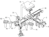
Fig. 1 is a schematic diagram of a logistics distribution package recycling device according to the present invention;
fig. 2 is a perspective view of a bag and box structure of the logistics distribution bag recycling device provided by the invention;
FIG. 3 is a perspective view of a vacuum chuck structure of the logistics distribution bag recycling device according to the present invention;
FIG. 4 is a perspective view of a concave supporting plate structure of the recycling device for logistics distribution packages according to the present invention;
FIG. 5 is a perspective view of an adjusting screw structure of the logistics distribution bag recycling device provided by the invention;
fig. 6 is a perspective view of a movable slide rail structure of the logistics distribution bag recycling device provided by the invention;
fig. 7 is a perspective view of a transfer panel structure of a logistics distribution bag recycling device according to the present invention;
FIG. 8 is a perspective view of a clamping air rod structure of a recycling device for material distribution bags according to the present invention;
FIG. 9 is a perspective view of an eccentric rod structure of a logistics distribution bag recycling device according to the present invention;
fig. 10 is a perspective view of a supporting block structure of the logistics distribution bag recycling device provided by the invention;
fig. 11 is a perspective view of a gripper jaw structure of the logistics distribution bag recycling device provided by the invention;
fig. 12 is a perspective view of a pushing cylinder mechanism of the logistics distribution bag recycling device provided by the invention.
In the figure: 1. a first sheave conveyor; 11. a transmission plate; 2. packing in a box; 3. a support base; 31. a support panel; 32. a second sheave conveyor; 33. buffering the telescopic rod; 34. a vacuum generator; 35. a vacuum chuck; 36. a cargo conveyor belt; 4. clamping the gas rod; 41. a grabbing rod; 42. a rubber plate; 43. a limiting base; 44. mounting a rod; 45. a limiting rod; 46. a guide slide rail; 47. a limiting supporting block; 5. adjusting the screw rod; 51. a concave support plate; 52. a reduction motor; 53. supporting the threaded pipe sleeve; 54. supporting the sliding rod; 6. moving the slide rail; 61. mounting blocks; 62. transferring the panel; 63. a servo motor; 64. an adjustment groove; 65. an eccentric rod; 66. an adjustment port; 67. an adjusting block; 68. clamping a plate; 7. a support block; 71. a gantry; 72. a lifting cylinder; 73. a gripper jaw; 74. a rubber ball; 75. a hydraulic press; 76. a separating blade; 8. an arc-shaped clamping jaw; 81. a support frame; 82. a push cylinder; 83. a push rod; 84. a slide cylinder; 85. transfer arm.
Detailed Description
The technical solutions in the embodiments of the present invention will be clearly and completely described below with reference to the drawings in the embodiments of the present invention, and it is obvious that the described embodiments are only a part of the embodiments of the present invention, and not all of the embodiments.
Referring to fig. 1-12, a logistics distribution package recycling device comprises a first grooved pulley conveyor belt 1 for conveying logistics and a package box 2 for packing goods, wherein a transmission plate 11 is fixedly connected to the surface of a support at one end of the first grooved pulley conveyor belt 1, and a supporting base 3 is arranged on one side of the first grooved pulley conveyor belt 1.
In order to fix the luggage case 2 and facilitate the grabbing and transferring of goods inside, the upper surface of the supporting base 3 is symmetrically and fixedly connected with a buffering telescopic rod 33, and a vacuum generator 34 is fixedly connected to the upper surface of the buffer telescopic rod 33, so that vacuum suction cups 35 are arranged on the upper surface of the vacuum generator 34 in a rectangular array, so that the upper surface of the vacuum chuck 35 is in sliding contact with the lower surface of the bag box 2, the lower surface of the vacuum generator 34 is provided with a weight sensor, so that when the container 2 on the vacuum suction cup 35 exceeds the predetermined value of the weight sensor, the existence of goods in the container 2 is proved, at this time, the vacuum generator 34 controls the vacuum suction cup 35 to perform the adsorption fixing to the bottom of the container 2, and then be convenient for get goods, in order to carry out the shock attenuation to the process of vacuum chuck 35 absorption to carry out the shock attenuation of buffering to support vacuum generator 34 through buffering telescopic link 33.
One side of supporting base 3 is provided with supporting panel 31, and supporting panel 31's upper end lower surface is provided with snatchs transfer device, snatchs transfer device and includes centre gripping gas pole 4, and carries out adjusting screw 5 of horizontal migration regulation action and the movable slide rail 6 that carries out radial regulation action to centre gripping gas pole 4, and adjusting screw 5 is the cross with centre gripping gas pole 4 and places.
In order to install the adjusting screw 5 on the surface of the supporting panel 31, thereby facilitating the rotation of the adjusting screw 5 and realizing the horizontal movement of the clamping air rod 4, a concave supporting plate 51 with a downward opening is fixedly connected to the lower surface of the upper end of the supporting panel 31, the inner surfaces of the two ends of the concave supporting plate 51 are rotatably connected with the outer surface of the adjusting screw 5 through the inner ring surface of a bearing, in order to drive the adjusting screw 5 to rotate, a speed reducing motor 52 is fixedly installed on the surface of one side of the concave supporting plate 51, and the outer surface of the output shaft of the speed reducing motor 52 is fixedly connected with the outer surface of one end of the adjusting screw 5 through a coupler.
In order to realize the horizontal movement adjustment of the clamping air rod 4, a supporting threaded pipe sleeve 53 is sleeved on the outer surface of the adjusting screw rod 5 in a threaded manner, and in order to guide and limit the movement of the supporting threaded pipe sleeve 53, supporting slide rods 54 are symmetrically and fixedly connected to the inner surfaces of two ends of the concave supporting plate 51, so that the surface of the supporting threaded pipe sleeve 53 is in sliding sleeved connection with the outer surface of the supporting slide rod 54.
In order to realize the radial movement of the clamping air rod 4, the movable slide rail 6 is required to be indirectly connected with the supporting threaded pipe sleeve 53, furthermore, an installation block 61 is slidably clamped on the outer surface of the movable slide rail 6, the upper surface of the installation block 61 is fixedly connected with the lower surface of the supporting threaded pipe sleeve 53, in order to realize the grabbing and transferring actions of the clamping air rod 4 on goods, a transferring panel 62 is fixedly connected with the lower surface of the movable slide rail 6, a servo motor 63 is fixedly installed on one side surface of the transferring panel 62, an adjusting groove 64 is formed in the other side surface of the transferring panel 62, the servo motor 63 on one side of the transferring panel 62 works, the clamping air rod 4 is controlled to move on the inner wall of the adjusting groove 64 in a track manner, and then the grabbing and transferring actions are realized.
In order to realize the clamping and transferring action of the clamping air rod 4, the outer surface of the output shaft of the servo motor 63 penetrates through the transferring panel 62 and is fixedly connected with an eccentric rod 65 through a coupler, an adjusting opening 66 is formed in the surface of the eccentric rod 65 in a penetrating mode, an adjusting block 67 is connected to the inner wall of the adjusting groove 64 in a sliding and clamping mode, one side surface of the adjusting block 67 is fixedly connected with clamping plates 68 in a symmetrical and fixedly connected mode through a connecting shaft, the opposite side surfaces of the two clamping plates 68 are connected with the two side surfaces of the eccentric rod 65 in a sliding mode, the servo motor 63 controls the eccentric rod 65 to rotate along a specified path, the eccentric rod 65 rotates to enable the clamping plates 68 connected with the connecting shaft to slide on the two sides of the adjusting opening 66, and the adjusting block 67 is pulled to rotate along a track in the adjusting groove 64.
In order to install the clamping gas rod 4, the grabbing rod 41 is fixedly connected to the surface of one side of one clamping plate 68, the lower surface of the grabbing rod 41 is fixedly connected to the surface of the clamping cylinder of the clamping gas rod 4, and in order to prevent goods from falling off in the clamping and transferring process, the rubber plate 42 is fixedly connected to the surface of the opposite side of the clamping gas rod 4.
In order to control the servo motor 63 to rotate forward and backward, the two sides of the adjusting groove 64 are provided with limiting bases 43, one side surface of each limiting base 43 is fixedly connected with one side surface of the transferring panel 62, the surface of the grabbing rod 41 is fixedly connected with an installation rod 44, the lower surfaces of the two ends of the installation rod 44 are fixedly connected with limiting rods 45, so that the servo motor 63 rotates backward to drive the eccentric rod 65 to rotate, the lower surface of the limiting rod 45 at one end of the grabbing rod 41 at one side of the clamping plate 68 drawn by the eccentric rod 65 is contacted with the upper surface of the limiting base 43, the clamping air rod 4 and the rubber plate 42 at the lower surface of the grabbing rod 41 clamp the goods in the bag box 2, the servo motor 63 can rotate forward to drive the eccentric rod 65 to the other end of the adjusting groove 64, the goods transferred by the clamping air rod 4, in order to realize the support when the grabbing rod 41 moves, the surface of the lower end side of the transferring panel 62 is fixedly connected with a guide slide rail 46, the outer surface of the guide slide rail 46 is connected with a limit supporting block 47 in a sliding clamping mode, the surface of the limit supporting block 47 is movably sleeved with the outer surface of the grabbing rod 41 through a sliding opening formed in a penetrating mode, a goods conveying conveyor belt 36 is arranged on one side of the supporting base 3, the limit supporting block 47 is driven to slide on the outer surface of the guide slide rail 46 when the grabbing rod 41 moves left and right, and then goods clamped by the clamping air rod 4 are placed on the surface of the goods conveying conveyor belt 36 to be conveyed.
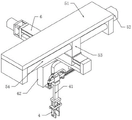
One side of supporting base 3 is provided with the second sheave conveyer belt 32 that is used for carrying on the package case 2, and the both sides of second sheave conveyer belt 32 are 45 degrees angles and are provided with the unpacking device, and the unpacking device is including being braced piece 7 of adjusting from top to bottom, and braced piece 7 struts the action to the position that 2 bottoms sticky tape of package case bond at the in-process that descends to in-process that continuously descends, makes package case 2 run through from top to bottom, thereby is convenient for carry out folding recovery action to package case 2.
In order to realize the conveying of the packing box 2 and to disassemble the packing box, a portal frame 71 is arranged above the second sheave conveyor belt 32, in order to clamp the packing box 2 to a certain height and to disassemble the packing box, lifting cylinders 72 are fixedly connected to both ends of the upper surface of the portal frame 71, a piston rod of each lifting cylinder 72 penetrates through the upper end of the portal frame 71 and is fixedly connected with a clamping claw 73, in order to prevent the packing box 2 from falling off, a rubber ball 74 is fixedly connected to the surface of the clamping claw 73 on the opposite side, and the surface of the rubber ball 74 is in sliding contact with the surface of the upper end of the obliquely symmetrical right-angle part of the packing box 2.
In order to expand the bottom of the bag box 2 and facilitate the flattening treatment of the bag box 2, a hydraulic press 75 is fixedly connected to the upper surface of the middle part of the portal frame 71, the surface of a piston rod of the hydraulic press 75 is fixedly connected with the upper surface of the supporting block 7, and in order to accelerate the separation of the bottom of the bag box 2, a separating blade 76 is fixedly connected to the lower surface of the supporting block 7.
The both sides of second sheave conveyer belt 32 are 45 degrees angles and still are provided with and press from both sides flat device, press from both sides flat device and include arc clamping jaw 8, are two arc clamping jaws 8 that 45 degrees angles are relative and press from both sides flat processing to the package case 2 that runs through to make things convenient for package case 2 to carry out the pile up neatly and can the reutilization.
In order to flatten the package box 2 with the bottom penetrating through, two sides of the second sheave conveyor belt 32 at an angle of 45 degrees are provided with support frames 81, the upper surface of one end of each support frame 81 is fixedly provided with a push cylinder 82, the surface of a piston rod of each push cylinder 82 is fixedly connected with a push rod 83, so that the surface of one side of each push rod 83 is fixedly connected with the surface of one side of each arc-shaped clamping jaw 8, in order to guide and limit the pushing process of the push rods 83, the upper surface of each support frame 81 is fixedly connected with a sliding barrel 84, and the inner wall of each sliding barrel 84 is movably sleeved with the outer surface of each push rod 83; a transfer robot 85 is provided at one side of the second sheave conveyor 32.
Thereby press from both sides flat device through setting up, can flatten the package to allocating, thereby the pile up neatly is retrieved to it is convenient, at the in-process of adjusting, promote through push cylinder 82, make push rod 83 promote arc clamping jaw 8, the surface adaptation package case 2's of arc clamping jaw 8 right angle department shape, thereby promote the back at arc clamping jaw 8, can make two arc clamping jaws 8 press from both sides flat package case 2, the arm 85 is transferred to the rethread this moment and will press from both sides flat package case 2 and carry out the centre gripping and transfer and carry out the pile up neatly, thereby make things convenient for the reutilization.
The working principle is as follows: in the specific embodiment of the invention, the bag box 2 with the express delivery at the bottom layer is placed on the upper surface of the first grooved pulley conveyor belt 1 for conveying at uniform intervals, and in order to fix the bag box 2, the goods in the bag box are convenient to grab and transfer, so that the bag box 2 is moved to the upper surface of the vacuum chuck 35 through the transmission plate 11, the lower surface of the vacuum generator 34 is provided with the weight sensor, so that when the bag box 2 on the vacuum chuck 35 exceeds the preset value of the weight sensor, the goods are proved to be stored in the bag box 2, and at the moment, the vacuum generator 34 controls the vacuum chuck 35 to adsorb and fix the bottom of the bag box 2, so that the goods can be conveniently taken;
after the bag box 2 is fixed, the speed reduction motor 52 on one side of the concave support plate 51 on the surface of the support panel 31 works to control the adjusting screw 5 to rotate, so that the support threaded pipe sleeve 53 horizontally moves for a certain distance on the outer surface of the adjusting screw 5, and in the moving process, the surface of the support threaded pipe sleeve 53 slides on the outer surface of the support sliding rod 54;
the supporting threaded sleeve 53 drives the mounting block 61 to move, the mounting block 61 is clamped with the movable slide rail 6, so that the movable slide rail 6 radially moves a certain distance in the mounting block 61, at the moment, the servo motor 63 on one side of the transfer panel 62 works to control the eccentric rod 65 to rotate, the traction clamping plate 68 slides on two sides of the adjusting opening 66, the traction adjusting block 67 performs track rotation in the adjusting groove 64, the servo motor 63 rotates reversely to drive the eccentric rod 65 to rotate, the eccentric rod 65 pulls the lower surface of the limiting rod 45 at one end of the grabbing rod 41 on one side of the clamping plate 68 to contact with the upper surface of the limiting base 43, at the moment, the clamping air rod 4 on the lower surface of the grabbing rod 41 and the rubber plate 42 clamp the goods in the bag box 2, further, the servo motor 63 can rotate forwardly to drive the eccentric rod 65 to the other end of the adjusting groove 64, further, the clamping air rod 4 drives the goods to be transferred to the surface of the goods conveying conveyor belt 36 for conveying, when the grabbing rod 41 moves left and right, the limiting supporting block 47 is driven to slide on the outer surface of the guide sliding rail 46;
the package box 2 which has taken the goods is intermittently conveyed on the upper surface of the second sheave conveyor belt 32, when the package box 2 is conveyed to the lower surface of the portal frame 71, the lifting cylinders 72 with the upper surfaces in oblique symmetry drive the clamping claws 73 to descend to a certain height, so that the clamping claws 73 grab the upper ends of the oblique opposite angles of the package box 2, the lifting cylinders 72 drive the package box 2 to ascend to a certain height, the hydraulic press 75 works to prop open the bottom of the package box 2 by the supporting blocks 7, and the separating blades 76 can accelerate the separation of the bottom of the package box 2;
rethread pushes away actuating cylinder 82 and promotes, makes push rod 83 promote arc clamping jaw 8, and the surface adaptation package case 2 of arc clamping jaw 8's right angle department shape to after arc clamping jaw 8 promotes, can make two arc clamping jaws 8 press from both sides flat package case 2, the rethread is transferred arm 85 and is carried out the centre gripping with pressing from both sides flat package case 2 and transfer and carry out the pile up neatly this moment, thereby makes things convenient for the reutilization.
The above description is only for the preferred embodiment of the present invention, but the scope of the present invention is not limited thereto, and any person skilled in the art should be considered to be within the technical scope of the present invention, and the technical solutions and the inventive concepts thereof according to the present invention should be equivalent or changed within the scope of the present invention.
Claims (10)
1. The utility model provides a commodity circulation divides group to dial package recovery processing equipment, includes first sheave conveyer belt (1) that is used for carrying commodity circulation and carries out package case (2) of vanning to the goods which characterized in that: the surface of a bracket at one end of the first grooved pulley conveyor belt (1) is fixedly connected with a transmission plate (11), and one side of the first grooved pulley conveyor belt (1) is provided with a supporting base (3);
a supporting panel (31) is arranged on one side of the supporting base (3), a grabbing and transferring device is arranged on the lower surface of the upper end of the supporting panel (31), the grabbing and transferring device comprises a clamping air rod (4), an adjusting screw (5) for performing horizontal movement and adjustment actions on the clamping air rod (4), and a moving slide rail (6) for performing radial adjustment actions on the clamping air rod (4), and the adjusting screw (5) and the clamping air rod (4) are placed in a cross shape;
a second grooved pulley conveyor belt (32) used for conveying the packing box (2) is arranged on one side of the supporting base (3), a unpacking device is arranged on two sides of the second grooved pulley conveyor belt (32) at an angle of 45 degrees and comprises a supporting block (7) which is adjusted up and down, the supporting block (7) is used for opening a part bonded with an adhesive tape at the bottom of the packing box (2) in the descending process and enabling the packing box (2) to penetrate through the packing box (2) up and down in the continuous descending process, so that the packing box (2) can be folded and recovered conveniently;
the both sides of second sheave conveyer belt (32) are 45 degrees angles and still are provided with and press from both sides flat device, press from both sides flat device and include arc clamping jaw (8), be two that 45 degrees angles are relative arc clamping jaw (8) are to running through package case (2) are pressed from both sides flat processing, thereby it is convenient package case (2) are carried out the pile up neatly and can the reutilization.
2. The logistics distribution package recycling device according to claim 1, wherein: the upper surface of support base (3) is symmetry fixedly connected with buffering telescopic link (33), the last fixed surface of buffering telescopic link (33) is connected with vacuum generator (34), the upper surface of vacuum generator (34) is the rectangle array and is provided with vacuum chuck (35), the upper surface of vacuum chuck (35) with the lower surface sliding contact of package case (2).
3. The logistics distribution package recycling device according to claim 1, wherein: the utility model discloses a support panel's (31) upper end lower surface fixed connection has concave type backup pad (51) that the opening faces down, the inner circle surface that the both ends internal surface of concave type backup pad (51) passed through the bearing with adjusting screw (5)'s surface rotates and connects, one side fixed surface of concave type backup pad (51) installs gear motor (52), gear motor (52)'s output shaft surface pass through the shaft coupling with the one end fixed surface of adjusting screw (5) is connected.
4. The logistics distribution package recycling device according to claim 3, wherein: the outer surface of the adjusting screw rod (5) is in threaded sleeve connection with a supporting threaded sleeve (53), the inner surfaces of two ends of the concave supporting plate (51) are symmetrically and fixedly connected with supporting sliding rods (54), and the surface of the supporting threaded sleeve (53) is in sliding sleeve connection with the outer surface of the supporting sliding rod (54).
5. The logistics distribution package recycling device of claim 4, wherein: the surface slip joint of moving slide rail (6) has installation piece (61), the upper surface of installation piece (61) with the lower fixed surface who supports threaded pipe box (53) is connected, the lower fixed surface of moving slide rail (6) is connected with and transfers panel (62), one side fixed surface who transfers panel (62) installs servo motor (63), adjustment tank (64) have been seted up on the opposite side surface of transferring panel (62).
6. The logistics distribution package recycling device according to claim 5, wherein: the outer surface of an output shaft of the servo motor (63) penetrates through the transfer panel (62) and is fixedly connected with an eccentric rod (65) through a coupler, an adjusting opening (66) is formed in the surface of the eccentric rod (65) in a penetrating mode, an adjusting block (67) is clamped on the inner wall of the adjusting groove (64) in a sliding mode, clamping plates (68) are fixedly connected to one side surface of the adjusting block (67) in a symmetrical mode through connecting shafts, and the opposite side surfaces of the two clamping plates (68) are connected with the two side surfaces of the eccentric rod (65) in a sliding mode;
one side surface of one of the clamping plates (68) is fixedly connected with a grabbing rod (41), the lower surface of the grabbing rod (41) is fixedly connected with the surface of a clamping cylinder of the clamping air rod (4), and the surface of the opposite side of the clamping air rod (4) is fixedly connected with a rubber plate (42).
7. The logistics distribution package recycling device of claim 6, wherein: limiting bases (43) are arranged on two sides of the adjusting groove (64), one side surface of each limiting base (43) is fixedly connected with one side surface of the transfer panel (62), the surface of the grabbing rod (41) is fixedly connected with an installation rod (44), and the lower surfaces of two ends of each installation rod (44) are fixedly connected with limiting rods (45);
the surface of one side of the lower end of the transferring panel (62) is fixedly connected with a guide sliding rail (46), the outer surface of the guide sliding rail (46) is slidably clamped with a limit supporting block (47), the surface of the limit supporting block (47) is movably sleeved with the outer surface of the grabbing rod (41) through a sliding opening formed in a penetrating mode, and a goods conveying and conveying belt (36) is arranged on one side of the supporting base (3).
8. The logistics distribution package recycling device according to claim 1, wherein: a portal frame (71) is arranged above the second grooved pulley conveyor belt (32), a lifting cylinder (72) is fixedly connected to two ends of the upper surface of the portal frame (71), a piston rod of the lifting cylinder (72) penetrates through the upper end of the portal frame (71) and is fixedly connected with a clamping jaw (73), a rubber ball (74) is fixedly connected to the surface of one side, opposite to the clamping jaw (73), of the clamping jaw, and the surface of the rubber ball (74) is in sliding contact with the surface of the upper end of the oblique symmetrical right-angle position of the packing box (2).
9. The logistics distribution package recycling device according to claim 8, wherein: the upper surface of the middle part of the portal frame (71) is fixedly connected with a hydraulic machine (75), the surface of a piston rod of the hydraulic machine (75) is fixedly connected with the upper surface of the supporting block (7), and the lower surface of the supporting block (7) is fixedly connected with a separating blade (76).
10. The logistics distribution package recycling device of claim 1, wherein: two sides of the second grooved pulley conveyor belt (32) which are at an angle of 45 degrees are provided with support frames (81), the upper surface of one end of each support frame (81) is fixedly provided with a pushing cylinder (82), the surface of a piston rod of each pushing cylinder (82) is fixedly connected with a push rod (83), the surface of one side of each push rod (83) is fixedly connected with the surface of one side of each arc-shaped clamping jaw (8), the upper surface of each support frame (81) is fixedly connected with a sliding barrel (84), and the inner wall of each sliding barrel (84) is movably sleeved with the outer surface of each push rod (83);
and a transfer mechanical arm (85) is arranged on one side of the second grooved pulley conveyor belt (32).
Priority Applications (1)
| Application Number | Priority Date | Filing Date | Title |
|---|---|---|---|
| CN202210783558.6A CN115009767A (en) | 2022-07-05 | 2022-07-05 | Commodity circulation divides and dials a packet recovery processing equipment |
Applications Claiming Priority (1)
| Application Number | Priority Date | Filing Date | Title |
|---|---|---|---|
| CN202210783558.6A CN115009767A (en) | 2022-07-05 | 2022-07-05 | Commodity circulation divides and dials a packet recovery processing equipment |
Publications (1)
| Publication Number | Publication Date |
|---|---|
| CN115009767A true CN115009767A (en) | 2022-09-06 |
Family
ID=83079091
Family Applications (1)
| Application Number | Title | Priority Date | Filing Date |
|---|---|---|---|
| CN202210783558.6A Withdrawn CN115009767A (en) | 2022-07-05 | 2022-07-05 | Commodity circulation divides and dials a packet recovery processing equipment |
Country Status (1)
| Country | Link |
|---|---|
| CN (1) | CN115009767A (en) |
Cited By (2)
| Publication number | Priority date | Publication date | Assignee | Title |
|---|---|---|---|---|
| CN115417149A (en) * | 2022-10-09 | 2022-12-02 | 兰州工业学院 | Stacking mechanical device for transferring parts |
| CN117566395A (en) * | 2024-01-16 | 2024-02-20 | 常州万码智能科技有限公司 | Full-automatic weighing equipment and method for automatically positioning enamelled rectangular wire based on visual guidance |
-
2022
- 2022-07-05 CN CN202210783558.6A patent/CN115009767A/en not_active Withdrawn
Cited By (3)
| Publication number | Priority date | Publication date | Assignee | Title |
|---|---|---|---|---|
| CN115417149A (en) * | 2022-10-09 | 2022-12-02 | 兰州工业学院 | Stacking mechanical device for transferring parts |
| CN117566395A (en) * | 2024-01-16 | 2024-02-20 | 常州万码智能科技有限公司 | Full-automatic weighing equipment and method for automatically positioning enamelled rectangular wire based on visual guidance |
| CN117566395B (en) * | 2024-01-16 | 2024-03-12 | 常州万码智能科技有限公司 | Full-automatic weighing equipment and method for automatically positioning enamelled rectangular wire based on visual guidance |
Similar Documents
| Publication | Publication Date | Title |
|---|---|---|
| CN115009767A (en) | Commodity circulation divides and dials a packet recovery processing equipment | |
| CN112173263B (en) | Full-automatic ton bag packagine machine | |
| CN107055108A (en) | Point pile induction system automatically of air-entrained concrete building block pallet | |
| CN210551234U (en) | Bidirectional movement's transportation manipulator | |
| CN108382650B (en) | Grabbing type bagging machine | |
| CN110803365A (en) | Automatic assembling equipment for production and processing of protection plates | |
| CN109132002A (en) | A kind of lithium battery automatic packaging equipment | |
| CN109866951A (en) | A kind of high speed bottom sealed plastic packaging machine | |
| CN113734544A (en) | Kit packaging equipment | |
| CN110498090A (en) | A kind of automatic packing device and its application method | |
| CN210364519U (en) | Novel automatic packing machine for glass panels | |
| CN109367903A (en) | A kind of packing box position-changing tool | |
| CN213294028U (en) | Automatic marking production line for aluminum template products | |
| CN211544190U (en) | Automatic assembling equipment for production and processing of protection plates | |
| CN212023220U (en) | Intelligent box feeding and opening integrated system | |
| CN209634816U (en) | A kind of packing box position-changing tool | |
| CN115571415A (en) | Full-automatic bag feeding machine for ton bag packaging | |
| CN210942464U (en) | Vertical intelligent vanning equipment | |
| CN212830975U (en) | Automatic carrying system of bag sealing machine | |
| CN210761547U (en) | Cigarette bagging and sorting line | |
| CN110641970B (en) | Thermal insulation mortar transportation and stacking device and method | |
| CN113716123A (en) | Automatic sheet boxing device, production line and application of automatic sheet boxing device | |
| CN112498820A (en) | Intelligent optimal detection self-contained equipment | |
| CN112441424A (en) | Automatic empty tray arranging mechanism | |
| CN218477727U (en) | Bag feeding machine for ton bag packaging |
Legal Events
| Date | Code | Title | Description |
|---|---|---|---|
| PB01 | Publication | ||
| PB01 | Publication | ||
| SE01 | Entry into force of request for substantive examination | ||
| SE01 | Entry into force of request for substantive examination | ||
| WW01 | Invention patent application withdrawn after publication | ||
| WW01 | Invention patent application withdrawn after publication |
Application publication date: 20220906 |