CN115006182A - Portable obstetrical and gynecological nursing delivery assisting device - Google Patents
Portable obstetrical and gynecological nursing delivery assisting device Download PDFInfo
- Publication number
- CN115006182A CN115006182A CN202210884551.3A CN202210884551A CN115006182A CN 115006182 A CN115006182 A CN 115006182A CN 202210884551 A CN202210884551 A CN 202210884551A CN 115006182 A CN115006182 A CN 115006182A
- Authority
- CN
- China
- Prior art keywords
- fixedly connected
- wall
- fixed connection
- portable
- air bag
- Prior art date
- Legal status (The legal status is an assumption and is not a legal conclusion. Google has not performed a legal analysis and makes no representation as to the accuracy of the status listed.)
- Withdrawn
Links
Images




Classifications
-
- A—HUMAN NECESSITIES
- A61—MEDICAL OR VETERINARY SCIENCE; HYGIENE
- A61G—TRANSPORT, PERSONAL CONVEYANCES OR ACCOMMODATION SPECIALLY ADAPTED FOR PATIENTS OR DISABLED PERSONS; OPERATING TABLES OR CHAIRS; CHAIRS FOR DENTISTRY; FUNERAL DEVICES
- A61G13/00—Operating tables; Auxiliary appliances therefor
- A61G13/10—Parts, details or accessories
- A61G13/12—Rests specially adapted therefor; Arrangements of patient-supporting surfaces
- A61G13/1205—Rests specially adapted therefor; Arrangements of patient-supporting surfaces for specific parts of the body
- A61G13/1245—Knees, upper or lower legs
-
- A—HUMAN NECESSITIES
- A61—MEDICAL OR VETERINARY SCIENCE; HYGIENE
- A61B—DIAGNOSIS; SURGERY; IDENTIFICATION
- A61B90/00—Instruments, implements or accessories specially adapted for surgery or diagnosis and not covered by any of the groups A61B1/00 - A61B50/00, e.g. for luxation treatment or for protecting wound edges
- A61B90/10—Instruments, implements or accessories specially adapted for surgery or diagnosis and not covered by any of the groups A61B1/00 - A61B50/00, e.g. for luxation treatment or for protecting wound edges for stereotaxic surgery, e.g. frame-based stereotaxis
- A61B90/14—Fixators for body parts, e.g. skull clamps; Constructional details of fixators, e.g. pins
-
- A—HUMAN NECESSITIES
- A61—MEDICAL OR VETERINARY SCIENCE; HYGIENE
- A61G—TRANSPORT, PERSONAL CONVEYANCES OR ACCOMMODATION SPECIALLY ADAPTED FOR PATIENTS OR DISABLED PERSONS; OPERATING TABLES OR CHAIRS; CHAIRS FOR DENTISTRY; FUNERAL DEVICES
- A61G13/00—Operating tables; Auxiliary appliances therefor
- A61G13/0009—Obstetrical tables or delivery beds
-
- A—HUMAN NECESSITIES
- A61—MEDICAL OR VETERINARY SCIENCE; HYGIENE
- A61G—TRANSPORT, PERSONAL CONVEYANCES OR ACCOMMODATION SPECIALLY ADAPTED FOR PATIENTS OR DISABLED PERSONS; OPERATING TABLES OR CHAIRS; CHAIRS FOR DENTISTRY; FUNERAL DEVICES
- A61G13/00—Operating tables; Auxiliary appliances therefor
- A61G13/10—Parts, details or accessories
- A61G13/12—Rests specially adapted therefor; Arrangements of patient-supporting surfaces
- A61G13/128—Rests specially adapted therefor; Arrangements of patient-supporting surfaces with mechanical surface adaptations
- A61G13/1285—Rests specially adapted therefor; Arrangements of patient-supporting surfaces with mechanical surface adaptations having modular surface parts, e.g. being replaceable or turnable
-
- A—HUMAN NECESSITIES
- A61—MEDICAL OR VETERINARY SCIENCE; HYGIENE
- A61G—TRANSPORT, PERSONAL CONVEYANCES OR ACCOMMODATION SPECIALLY ADAPTED FOR PATIENTS OR DISABLED PERSONS; OPERATING TABLES OR CHAIRS; CHAIRS FOR DENTISTRY; FUNERAL DEVICES
- A61G2200/00—Information related to the kind of patient or his position
- A61G2200/10—Type of patient
- A61G2200/12—Women
Landscapes
- Health & Medical Sciences (AREA)
- Life Sciences & Earth Sciences (AREA)
- Animal Behavior & Ethology (AREA)
- General Health & Medical Sciences (AREA)
- Veterinary Medicine (AREA)
- Public Health (AREA)
- Engineering & Computer Science (AREA)
- Biomedical Technology (AREA)
- Surgery (AREA)
- Heart & Thoracic Surgery (AREA)
- Medical Informatics (AREA)
- Molecular Biology (AREA)
- Neurosurgery (AREA)
- Oral & Maxillofacial Surgery (AREA)
- Nuclear Medicine, Radiotherapy & Molecular Imaging (AREA)
- Pathology (AREA)
- Gynecology & Obstetrics (AREA)
- External Artificial Organs (AREA)
Abstract
The invention provides a portable obstetrical and gynecological nursing delivery assisting device which comprises a box body, wherein a partition plate is fixedly connected to the inner wall of the box body, a ratchet mechanism is fixedly connected to the center of the surface of the partition plate, and a transmission gear is fixedly connected to the surface of the output end of the ratchet mechanism. The air bag type nursing bed is small in structure, when the nursing bed is used, a user firstly places the box body at a proper position, outside air enters the nursing bed through the air suction port through the air suction pump, the air is input into the air bag through the air conveying pipe and the air bag is enlarged, meanwhile, the sealing plate is extruded to rotate through the hinge, and the air bag main body is extruded out through the expansion port, so that the main part of the air bag is positioned outside.
Description
Technical Field
The invention relates to the technical field of gynecological operation auxiliary equipment, in particular to a portable gynecological nursing delivery assisting device.
Background
The obstetrics and gynecology department is one of four main subjects of clinical medicine, mainly researches the etiology, pathology, diagnosis and prevention of female reproductive organ diseases, physiological and pathological changes of pregnancy and delivery, prevention and diagnosis and treatment of high-risk pregnancy and dystocia, female reproductive endocrine, female health care and the like, deep research of medical basic theories such as modern molecular biology, oncology, genetics, reproductive endocrinology, immunology and the like and the progress of clinical medicine diagnosis and treatment detection technology, widens and deepens the development of gynecological science, plays an important role in ensuring the body and reproductive health of women and preventing and treating various gynecological diseases, and helps delivery refers to a series of measures taken before and during labor for enabling a fetus to be delivered out of a maternal birth canal smoothly;
in the prior art, application No.: CN202010907391.0 (publication No. CN 111870357A) discloses a portable obstetrical and gynecological nursing midwifery device, which comprises a third support plate, wherein a first sliding block is connected inside a first sliding rail in a sliding manner, a first shell is welded on one side, away from the first support plate, of the first sliding block, one end, away from a third limit plate, of a first support rod penetrates through the first shell, an arc-shaped plate is welded on one end, away from the first support rod, of the first support rod, and a rubber pad is bonded on one side, away from the first support rod, of the arc-shaped plate; when the device is used, the legs of a patient are clamped by arranging the arc-shaped plate, the first supporting rod is arranged to be matched with the third limiting plate and the third spring, so that the arc-shaped plate can clamp the patients with different body types, and the first sliding block is arranged to slide in the first sliding rail, so that the device can assist in expanding the pelvic floor;
although the technical scheme solves the problems that the labor is usually used for fixing the legs of the patient in the midwifery process, redundant labor is consumed, and subsequent midwifery work is inconvenient to carry out, the device is large in size and inconvenient to move, a mechanism facilitating the lying of the body of the pregnant woman does not exist, the device is matched with a midwifery platform on the market to use, and emergency use is inconvenient to carry out, so that the portable obstetrical and gynecological nursing midwifery device is provided.
Disclosure of Invention
In view of the above, it is desirable to provide a portable obstetrical and gynecological nursing midwifery device, which solves or alleviates the technical problems in the prior art, and at least provides a beneficial choice.
The technical scheme of the embodiment of the invention is realized as follows: a portable obstetrical and gynecological nursing delivery assisting device comprises a box body, wherein a partition plate is fixedly connected to the inner wall of the box body, a ratchet mechanism is fixedly connected to the center of the surface of the partition plate, a transmission gear is fixedly connected to the surface of the output end of the ratchet mechanism, a rotating part is fixedly connected to the top end of the surface of the output end of the ratchet mechanism, an air suction pump is arranged on one side of a protective shell, and an air delivery pipe is fixedly connected to the output end of the air suction pump;
the surface of the top end of the box body is provided with a left sliding groove and a right sliding groove, the inner wall of the sliding groove is connected with a left sliding block and a right sliding block in a sliding manner, the left sliding block is fixedly connected with a second sliding plate, the right sliding block is fixedly connected with a first sliding plate, one surfaces of the first sliding plate and the second sliding plate are both fixedly connected with a plurality of gear teeth matched with the transmission gear, and the first sliding plate and the second sliding plate are both meshed with the transmission gear through the gear teeth;
the surfaces of the first sliding plate and the second sliding plate are both fixedly connected with an adjusting mechanism, and one end of the adjusting mechanism is fixedly connected with a fixing part;
the back of box has seted up the inflation mouth, the below of division board is equipped with the gasbag, the gas-supply pipe is connected with the gasbag, the extraction opening has all been seted up on the surface of box both sides.
Preferably: ratchet includes protective housing, fixed connection at the fixed bearing of protective housing inner wall, fixed connection in the pivot of fixed bearing inner wall, fixed connection at the ratchet on pivot surface, fixed connection at the sliding frame of protective housing inner wall, fixed connection at the first electric telescopic handle of sliding frame inner wall, fixed connection at the slip base block of first electric telescopic handle output and the pawl of connecting through the axis of rotation.
Preferably, the following components: the adjusting mechanism comprises a connecting pipe, a second electric telescopic rod fixedly connected to the inner wall of the connecting pipe, a supporting bent rod fixedly connected to the output end of the second electric telescopic rod, a fixed pipe fixedly connected to one end of the supporting bent rod, a connecting bearing fixedly connected to the inner wall of the fixing pipe, and a rotating rod fixedly connected to the inner ring of the connecting bearing.
Preferably: the inner wall fixedly connected with hinge of inflation mouth, the one side fixedly connected with closing plate of hinge.
Preferably: the inner wall fixedly connected with dust of extraction opening filters the shell, the inner wall fixedly connected with non-woven fabrics of dust filtration shell filters the cotton.
Preferably: both sides of the box body are fixedly connected with friction parts.
Preferably: the inner wall of the fixing part is fixedly connected with a silica gel gasket.
Preferably: still including seting up the mounting groove in the fixed part bottom, the extraction chamber has been seted up to the inner wall inside fixed of fixed part, a plurality of adsorption hole has been seted up on the surface of fixed part, the adsorption hole link up with the extraction chamber mutually, the inner wall fixedly connected with miniature aspiration pump of mounting groove, the input of miniature aspiration pump extends to the extraction chamber, the surface covering of fixed part has medical gauze layer.
Preferably: the device is characterized by further comprising a first electromagnet fixedly connected to the inner wall of the fixing portion, wherein the surface of the first electromagnet is magnetically connected with a second electromagnet, and the surface of the second electromagnet is fixedly connected with an arc-shaped fixing rubber belt.
Preferably: still include the water injection pipe of fixed connection on the gasbag surface, the water injection pipe is for lining up with the gasbag, the surface of water injection pipe is equipped with the ooff valve, the bottom fixedly connected with drain pipe of gasbag, the inner wall of drain pipe is seted up there is the internal thread, the inner wall threaded connection of drain pipe has the sealing plug, the fixed surface of gasbag bottom is connected with the gasket
Due to the adoption of the technical scheme, the embodiment of the invention has the following advantages:
the air bag type nursing bed is small in structure, when the nursing bed is used, a user firstly places a box body at a proper position, outside air enters the nursing bed through an air suction port through an air suction pump, the air is input into an air bag through an air conveying pipe and the air bag is enlarged, meanwhile, a sealing plate is extruded to rotate through a hinge, and an air bag main body is extruded out through an expansion port, so that the main part of the air bag is positioned outside and can be understood by combining with the attached drawings, a pregnant woman can lie on the nursing bed conveniently, the leg of the pregnant woman can be placed on the surface of a fixing part, and the problem that the nursing bed needs to be matched with the nursing bed to be used is solved through the technical scheme.
The rotating part is manually rotated by a worker, so that the rotating shaft drives the transmission gear to rotate, the first sliding plate and the second sliding plate are driven by gear teeth to slide in the sliding groove through the sliding block, the first sliding plate and the second sliding plate move outwards under the action of the transmission gear, and the fixed part moves outwards through the adjusting mechanism, so that the gap between the two legs of the pregnant woman is adjusted, and the delivery of medical care personnel is facilitated.
The medical gauze layer is reasonable in structure, when the medical gauze layer is used, a user needs to place the shank on the surface of the fixing portion, the medical gauze layer is contacted with the user, when the medical gauze layer is used, the user places the shank on the surface of the fixing portion, air is extracted through the extraction cavity and the adsorption hole through the miniature air extracting pump, negative pressure is generated, the effect that the user adsorbs the shank is achieved (the medical gauze layer has ventilation), the shank of the user is coated through the arc-shaped fixing rubber belt, the electromagnet II in the pair is adsorbed, and the effect that the shank of the user is fixed through the arc-shaped fixing rubber belt is achieved.
The air bag device is reasonable in structure, when the air bag of the air bag device is inflated by the air pump, the air bag device is connected with the water injection pipe through the external water pipe, the switch valve is opened, water enters the air bag through the water pipe and the water injection pipe, the weight increasing effect on the air bag is achieved, the stability is improved, after the air bag device is used, the air bag is lifted by a worker for a short time and is taken out through rotating the sealing plug, the water in the air bag is discharged through the water discharge pipe, and the air bag device is in contact with the ground through the gasket, so that the problem that the air bag is damaged due to friction between the air bag and the ground after being used for many times is solved.
The foregoing summary is provided for the purpose of description only and is not intended to be limiting in any way. In addition to the illustrative aspects, embodiments, and features described above, further aspects, embodiments, and features of the present invention will be readily apparent by reference to the drawings and following detailed description.
Drawings
In order to more clearly illustrate the embodiments of the present application or the technical solutions in the prior art, the drawings needed to be used in the embodiments or technical descriptions will be briefly described below, it is obvious that the drawings in the following description are only some embodiments of the present application, and for those skilled in the art, other drawings can be obtained according to the drawings without creative efforts.
FIG. 1 is a first perspective view of the present invention;
FIG. 2 is a second perspective view of the present invention;
FIG. 3 is a schematic view of the inflated state of the air bag of the present invention;
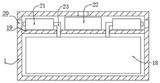
FIG. 4 is a sectional view of the case of the present invention;
FIG. 5 is a partial cross-sectional view of the connecting tube and support bent bar of the present invention;
FIG. 6 is a structural view of the ratchet mechanism of the present invention;
FIG. 7 is an enlarged view of the structure at A in FIG. 6 according to the present invention;
FIG. 8 is a diagram illustrating a structure of a fixing portion according to a second embodiment of the present invention;
FIG. 9 is a cross-sectional view of a third embodiment of the present invention.
Reference numerals: 1. a box body; 2. a sliding groove; 3. a first sliding plate; 4. a second sliding plate; 5. a rotating shaft; 6. a rotating part; 7. a connecting pipe; 8. supporting the bent rod; 9. a fixed tube; 10. a fixed part; 11. a dust filter shell; 12. a friction portion; 13. non-woven fabric filter cotton; 14. gear teeth; 15. a transmission gear; 16. a sealing plate; 17. a hinge; 18. an air bag; 19. a partition plate; 20. an air extraction opening; 21. an air pump; 22. a protective shell; 23. a gas delivery pipe; 24. a ratchet wheel; 25. a pawl; 26. a slide frame; 27. a first electric telescopic rod; 28. a second electric telescopic rod; 29. a micro air pump; 30. fixing the rubber belt in an arc shape; 31. an electromagnet I; 32. an electromagnet II; 33. a water injection pipe; 34. a drain pipe; 35. a gasket; 36. and (4) switching on and off the valve.
Detailed Description
In the following, only certain exemplary embodiments are briefly described. As those skilled in the art will recognize, the described embodiments may be modified in various different ways, all without departing from the spirit or scope of the present invention. Accordingly, the drawings and description are to be regarded as illustrative in nature, and not as restrictive.
The first embodiment of the present invention will be described in detail below with reference to the accompanying drawings.
As shown in fig. 1-7, an embodiment of the present invention provides a portable obstetrical and gynecological nursing midwifery device, which includes a box body 1, a partition plate 19 is fixedly connected to an inner wall of the box body 1, a ratchet mechanism is fixedly connected to a center of a surface of the partition plate 19, a transmission gear 15 is fixedly connected to a surface of an output end of the ratchet mechanism, a rotating part 6 is fixedly connected to a top end of a surface of the output end of the ratchet mechanism, an air suction pump 21 is arranged on one side of a protective shell 22, and an air pipe 23 is fixedly connected to an output end of the air suction pump 21;
the surface of the top end of the box body 1 is provided with a left sliding groove 2 and a right sliding groove 2, the inner wall of the sliding groove 2 is connected with a left sliding block and a right sliding block in a sliding manner, the left sliding block is fixedly connected with a second sliding plate 4, the right sliding block is fixedly connected with a first sliding plate 3, one surface of each of the first sliding plate 3 and the second sliding plate 4 is fixedly connected with a plurality of gear teeth 14 matched with a transmission gear 15, and the first sliding plate 3 and the second sliding plate 4 are both meshed with the transmission gear 15 through the gear teeth 14;
the surfaces of the first sliding plate 3 and the second sliding plate 4 are both fixedly connected with an adjusting mechanism, and one end of the adjusting mechanism is fixedly connected with a fixing part 10;
the back of the box body 1 is provided with an expansion opening, an air bag 18 is arranged below the partition plate 19, a gas pipe 23 is connected with the air bag 18, and the surfaces of two sides of the box body 1 are both provided with extraction openings 20;
when the pregnant woman lying on the pregnant woman needs to use the pregnant woman, the user firstly places the box body 1 at a proper position, the external air enters through the air suction port 20 through the air suction pump 21, the air is input into the air bag 18 through the air delivery pipe 23, the air bag 18 is enlarged, meanwhile, the sealing plate 16 is squeezed to rotate through the hinge 17, the main body of the air bag 18 is extruded through the expansion port, so that the main part of the air bag 18 is positioned outside, the pregnant woman can lie on the air bag conveniently, the leg of the pregnant woman can be placed on the surface of the fixing part 10, the rotating part 6 is rotated manually by the worker, the rotating shaft 5 drives the transmission gear 15 to rotate, the first sliding plate 3 and the second sliding plate 4 are meshed through the gear teeth 14 to be driven to slide in the sliding groove 2 through the sliding block, the first sliding plate 3 and the second sliding plate 4 are driven to move outwards due to the action of the transmission gear 15, the fixing part 10 is moved outwards by the adjusting mechanism, so that the gap between the two legs of the pregnant woman is adjusted, and the medical care personnel can take delivery conveniently.
In this embodiment, specifically: the ratchet mechanism comprises a protective shell 22, a fixed bearing fixedly connected to the inner wall of the protective shell 22, a rotating shaft 5 fixedly connected to the inner wall of the fixed bearing, a ratchet 24 fixedly connected to the surface of the rotating shaft 5, a sliding frame 26 fixedly connected to the inner wall of the protective shell 22, a first electric telescopic rod 27 fixedly connected to the inner wall of the sliding frame 26, a sliding base block fixedly connected to the output end of the first electric telescopic rod 27, and a pawl 25 rotatably connected through a rotating shaft, wherein a worker manually rotates the rotating part 6 to enable the rotating shaft 5 to drive the transmission gear 15 to rotate, and simultaneously, the first sliding plate 3 and the second sliding plate 4 are driven by meshing of the gear teeth 14 to slide in the sliding groove 2 through the sliding block, the ratchet 24 can also rotate, and the pawl 25 is combined to avoid reverse rotation of the ratchet 24, if the reverse rotation is needed, the pawl 25 is driven by the first electric telescopic rod 27 through the sliding base block to move upwards, thereby reversing the ratchet 24 under external force.
In this embodiment, specifically: adjustment mechanism includes connecting pipe 7, fixed connection is at the second electric telescopic handle 28 of connecting pipe 7 inner wall, fixed connection is at the support knee 8 of second electric telescopic handle 28 output, fixed connection is at the fixed pipe 9 that supports knee 8 one end, the connection bearing of the fixed pipe 9 inner wall of fixed connection and the rotary rod of fixed connection at the connection bearing inner loop, make through second electric telescopic handle 28 support knee 8 rise or descend in connecting pipe 7, reached and highly adjusted the height of fixed part 10, rotate in connecting the bearing through the rotary rod, reach the angle that makes fixed part 10 and adjust.
In this embodiment, specifically: the inner wall of the expansion opening is fixedly connected with a hinge 17, one surface of the hinge 17 is fixedly connected with a sealing plate 16, and the air bag 18 in the box body 1 is protected through the sealing plate 16.
In this embodiment, specifically: the shell 11 is crossed to the inner wall fixedly connected with dust of extraction opening 20, the inner wall fixedly connected with non-woven fabrics filter pulp 13 of shell 11 is crossed to the dust, filter the dust in the gas of air suction pump 21 suction through non-woven fabrics filter pulp 13, the equal fixedly connected with friction portion 12 in both sides of box 1, the staff is when carrying box 1, through the friction portion 12 increase friction, be convenient for carry, the inner wall fixedly connected with silica gel gasket of fixed part 10, the shank of pregnant woman is protected through the silica gel gasket.
The invention is in operation: s1, when in use, a user firstly places the box body 1 at a proper position, outside air enters through the air suction opening 20 through the air suction pump 21, the air is input into the air bag 18 through the air pipe 23, the air bag 18 is enlarged, and meanwhile, the sealing plate 16 is pressed to rotate through the hinge 17, so that the main body of the air bag 18 is extruded through the expansion opening, and the main part of the air bag 18 is positioned outside, which can be understood by combining with the attached figure 3, so that a pregnant woman lies on the box body, and the legs of the pregnant woman can be placed on the surface of the fixing part 10;
s2, a worker manually rotates the rotating part 6 to enable the rotating shaft 5 to drive the transmission gear 15 to rotate, and simultaneously the first sliding plate 3 and the second sliding plate 4 are meshed through the gear teeth 14 and driven to slide in the sliding groove 2 through the sliding blocks, the first sliding plate 3 and the second sliding plate 4 are moved outwards under the action of the transmission gear 15, the fixed part 10 is moved outwards through the adjusting mechanism, so that the gap between the two legs of a pregnant woman is adjusted, and the delivery of medical care personnel is facilitated;
s3, when the shaft 5 rotates, the ratchet wheel 24 will rotate synchronously and combine with the pawl 25 to avoid the reverse rotation of the ratchet wheel 24, if the reverse rotation is needed, the first electric telescopic rod 27 drives the pawl 25 to move upwards through the sliding base block, so that the ratchet wheel 24 rotates reversely under the condition of external force.
The second embodiment of the present invention will be described in detail below with reference to the above technical solutions.
As shown in fig. 8, the medical gauze mask further comprises a mounting groove formed at the bottom of the fixing portion 10, an extraction cavity is fixedly formed in the inner wall of the fixing portion 10, a plurality of adsorption holes are formed in the surface of the fixing portion 10, the adsorption holes are communicated with the extraction cavity, a micro air pump 29 is fixedly connected to the inner wall of the mounting groove, the input end of the micro air pump 29 extends to the extraction cavity, the medical gauze mask further comprises a first electromagnet 31 fixedly connected to the inner wall of the fixing portion 10, a second electromagnet 32 is magnetically connected to the surface of the first electromagnet 31, an arc-shaped fixing rubber belt 30 is fixedly connected to the surface of the second electromagnet 32, and a medical gauze layer covers the surface of the fixing portion 10;
when the medical gauze patch is used, the surface of the fixing part 10 contacting with the user's home needs to be placed on, when the medical gauze patch is used, the user places the lower leg on the surface of the fixing part 10, air is extracted through the extraction cavity and the adsorption hole through the micro air extracting pump 29 to generate negative pressure, the effect of adsorbing the lower leg by the user is achieved (the medical gauze patch layer has ventilation), the lower leg of the user is coated through the arc-shaped fixing rubber belt 30, the electromagnet I31 is used for adsorbing the electromagnet II 32, and the effect of fixing the lower leg of the user is achieved through the arc-shaped fixing rubber belt 30.
The third embodiment of the present invention is described in detail below with reference to the above technical solutions.
As shown in fig. 9, the air bag type water injection device further comprises a water injection pipe (33) fixedly connected to the surface of the air bag (18), the water injection pipe (33) is communicated with the air bag (18), a switch valve (36) is arranged on the surface of the water injection pipe (33), a drain pipe (34) is fixedly connected to the bottom of the air bag (18), an internal thread is formed in the inner wall of the drain pipe (34), a sealing plug is connected to the inner wall of the drain pipe (34) in a threaded manner, and a gasket (35) is fixedly connected to the surface of the bottom of the air bag (18);
after the air bag 18 of the device is inflated by the air pump 21, the air bag is connected with the water injection pipe 33 through the external water pipe, the switch valve 36 is opened again, water enters the air bag 18 through the water pipe and the water injection pipe 33, the weight increasing effect on the air bag 18 is achieved, the stability is improved, after the air bag is used, the air bag 8 is lifted by a worker for a short time and is taken out through rotating the sealing plug, the water in the air bag 18 is discharged through the water discharge pipe 24, the air bag is contacted with the ground through the gasket 25, and the problem that the air bag 18 rubs with the ground after being used for multiple times and is damaged is caused is avoided.
Due to the adoption of the technical scheme, the invention has the following advantages:
one, the user places suitable position to box 1 earlier, make external gas get into through extraction opening 20 through aspiration pump 21, make gaseous input to gasbag 18 through gas-supply pipe 23, and make gasbag 18 grow, can extrude closing plate 16 and rotate through closing page 17 simultaneously, make 18 main parts of gasbag extrude through the inflation mouth, thereby reach and make 18 main parts of gasbag be in the outside, can understand in combination with figure 3, be convenient for the pregnant woman to lie on, the pregnant woman's shank can be placed on fixed part 10 surface, through foretell technical scheme, the problem that needs supporting practise midwifery platform to use has been solved, the while device is when not using, the volume is less, be convenient for place.
Two, the manual rotating part 6 that rotates of staff, make pivot 5 drive gear 15 rotate, can slide in sliding tray 2 through the sliding block through the tooth of a cogwheel 14 meshing transmission first sliding plate 3 and second sliding plate 4 simultaneously, first sliding plate 3 and second sliding plate 4 are because of receiving drive gear 15's effect, its motion is outwards going on, make fixed part 10 move outward mutually through adjustment mechanism, reach the clearance that makes between two legs of pregnant woman and adjust, the medical personnel of being convenient for take over a student.
When the medical gauze patch is used, the surface of the fixing part 10 contacting with a user's home needs to be placed on, when the medical gauze patch is used, a user places the lower leg on the surface of the fixing part 10, air is extracted through the extraction cavity and the adsorption hole through the micro air extracting pump 29 to generate negative pressure, the effect of adsorbing the lower leg by the user is achieved (the medical gauze patch has ventilation), the lower leg of the user is coated through the arc-shaped fixing rubber belt 30, the electromagnet I31 is used for adsorbing the electromagnet II 32, and the effect of fixing the lower leg of the user is achieved through the arc-shaped fixing rubber belt 30.
Fourthly, the air bag device is reasonable in structure, after the air bag 18 is inflated by the air pump 21, the air bag device is connected with the water injection pipe 33 through an external water pipe, the switch valve 36 is opened, water enters the air bag 18 through the water pipe and the water injection pipe 33, the weight increasing effect on the air bag 18 is achieved, the stability is improved, after the air bag device is used, the air bag 8 is lifted by a worker for a short time and is taken out by rotating the sealing plug, the water in the air bag 18 is discharged through the water discharge pipe 24 and is contacted with the ground through the gasket 25, and the problem that the air bag 18 is abraded with the ground after being used for multiple times and is damaged is avoided.
The above description is only for the specific embodiment of the present invention, but the scope of the present invention is not limited thereto, and any person skilled in the art can easily conceive various changes or substitutions within the technical scope of the present invention, and these should be covered by the scope of the present invention. Therefore, the protection scope of the present invention shall be subject to the protection scope of the appended claims.
Claims (10)
1. The utility model provides a portable gynaecology and obstetrics nursing practise midwifery device, includes box (1), its characterized in that: a partition plate (19) is fixedly connected to the inner wall of the box body (1), a ratchet mechanism is fixedly connected to the center of the surface of the partition plate (19), a transmission gear (15) is fixedly connected to the surface of the output end of the ratchet mechanism, a rotating part (6) is fixedly connected to the top end of the surface of the output end of the ratchet mechanism, an air suction pump (21) is arranged on one side of the protective shell (22), and an air delivery pipe (23) is fixedly connected to the output end of the air suction pump (21);
the surface of the top end of the box body (1) is provided with a left sliding groove and a right sliding groove (2), the inner wall of the sliding groove (2) is connected with a left sliding block and a right sliding block in a sliding manner, the left sliding block is fixedly connected with a second sliding plate (4), the right sliding block is fixedly connected with a first sliding plate (3), one surfaces of the first sliding plate (3) and the second sliding plate (4) are fixedly connected with a plurality of gear teeth (14) matched with the transmission gear (15), and the first sliding plate (3) and the second sliding plate (4) are meshed and connected with the transmission gear (15) through the gear teeth (14);
the surfaces of the first sliding plate (3) and the second sliding plate (4) are both fixedly connected with an adjusting mechanism, and one end of the adjusting mechanism is fixedly connected with a fixing part (10);
the back of the box body (1) is provided with an expansion opening, an air bag (18) is arranged below the partition plate (19), the air conveying pipe (23) is connected with the air bag (18), and the surfaces of two sides of the box body (1) are provided with air suction openings (20).
2. The portable obstetrics and gynecology nursing midwifery device of claim 1, wherein: ratchet includes protective housing (22), fixed connection is at the fixed bearing of protective housing (22) inner wall, fixed connection is in pivot (5) of fixed bearing inner wall, fixed connection is in ratchet (24) on pivot (5) surface, fixed connection is in sliding frame (26) of protective housing (22) inner wall, fixed connection is in first electric telescopic handle (27) of sliding frame (26) inner wall, fixed connection is at the slip base block of first electric telescopic handle (27) output and through axis of rotation pawl (25) of connection.
3. The portable obstetrical and gynecological nursing midwifery device as claimed in claim 1, characterized in that: adjustment mechanism includes connecting pipe (7), fixed connection second electric telescopic handle (28), fixed connection at second electric telescopic handle (28) inner wall support knee (8), fixed connection support knee (8) of knee (8) one end, fixed connection are at fixed pipe (9) of supporting knee (8), the connection bearing of the fixed pipe of fixed connection (9) inner wall and the rotary rod of fixed connection at the connection bearing inner ring.
4. The portable obstetrics and gynecology nursing midwifery device of claim 1, wherein: the inner wall of inflation mouth fixedly connected with hinge (17), one side fixedly connected with closing plate (16) of hinge (17).
5. The portable obstetrics and gynecology nursing midwifery device of claim 1, wherein: the inner wall fixedly connected with dust of extraction opening (20) filters shell (11), the inner wall fixedly connected with non-woven fabrics of dust filtration shell (11) filters cotton (13).
6. The portable obstetrics and gynecology nursing midwifery device of claim 1, wherein: both sides of the box body (1) are fixedly connected with friction parts (12).
7. The portable obstetrics and gynecology nursing midwifery device of claim 1, wherein: the inner wall of the fixing part (10) is fixedly connected with a silica gel gasket.
8. The portable obstetrics and gynecology nursing midwifery device of claim 1, wherein: still including seting up the mounting groove in fixed part (10) bottom, the extraction chamber has been seted up to the inner wall inside fixed of fixed part (10), a plurality of adsorption hole has been seted up on the surface of fixed part (10), the adsorption hole link up with the extraction chamber mutually, the inner wall fixedly connected with miniature aspiration pump (29) of mounting groove, the input of miniature aspiration pump (29) extends to the extraction chamber, the surface covering of fixed part (10) has medical gauze layer.
9. The portable obstetrics and gynecology nursing midwifery device of claim 1, wherein: the novel magnetic switch is characterized by further comprising a first electromagnet (31) fixedly connected to the inner wall of the fixing portion (10), wherein the surface of the first electromagnet (31) is magnetically connected with a second electromagnet (32), and the surface of the second electromagnet (32) is fixedly connected with an arc-shaped fixing rubber belt (30).
10. The portable obstetrics and gynecology nursing midwifery device of claim 1, wherein: still include water injection pipe (33) of fixed connection on gasbag (18) surface, water injection pipe (33) and gasbag (18) are for lining up, the surface of water injection pipe (33) is equipped with ooff valve (36), the bottom fixedly connected with drain pipe (34) of gasbag (18), the internal thread has been seted up to the inner wall of drain pipe (34), the inner wall threaded connection of drain pipe (34) has the sealing plug, the fixed surface in gasbag (18) bottom is connected with gasket (35).
Priority Applications (1)
| Application Number | Priority Date | Filing Date | Title |
|---|---|---|---|
| CN202210884551.3A CN115006182A (en) | 2022-07-26 | 2022-07-26 | Portable obstetrical and gynecological nursing delivery assisting device |
Applications Claiming Priority (1)
| Application Number | Priority Date | Filing Date | Title |
|---|---|---|---|
| CN202210884551.3A CN115006182A (en) | 2022-07-26 | 2022-07-26 | Portable obstetrical and gynecological nursing delivery assisting device |
Publications (1)
| Publication Number | Publication Date |
|---|---|
| CN115006182A true CN115006182A (en) | 2022-09-06 |
Family
ID=83082451
Family Applications (1)
| Application Number | Title | Priority Date | Filing Date |
|---|---|---|---|
| CN202210884551.3A Withdrawn CN115006182A (en) | 2022-07-26 | 2022-07-26 | Portable obstetrical and gynecological nursing delivery assisting device |
Country Status (1)
| Country | Link |
|---|---|
| CN (1) | CN115006182A (en) |
Cited By (1)
| Publication number | Priority date | Publication date | Assignee | Title |
|---|---|---|---|---|
| CN120132100A (en) * | 2025-05-09 | 2025-06-13 | 浙江大学医学院附属第一医院(浙江省第一医院) | Detachable multifunctional scraping and cupping |
-
2022
- 2022-07-26 CN CN202210884551.3A patent/CN115006182A/en not_active Withdrawn
Cited By (1)
| Publication number | Priority date | Publication date | Assignee | Title |
|---|---|---|---|---|
| CN120132100A (en) * | 2025-05-09 | 2025-06-13 | 浙江大学医学院附属第一医院(浙江省第一医院) | Detachable multifunctional scraping and cupping |
Similar Documents
| Publication | Publication Date | Title |
|---|---|---|
| CN208769750U (en) | A kind of obstetrics and gynecology department Multifunctional dilator | |
| CN111494144A (en) | Obstetrical and gynecological nursing delivery assisting device | |
| CN112914929A (en) | Comprehensive inspection tester for obstetrics and gynecology department | |
| CN213098068U (en) | Obstetric apparatus for obstetrical department | |
| CN215020553U (en) | Inflatable pressurizing abdominal belt for obstetrics and gynecology department | |
| CN214128780U (en) | Obstetrical department uses multi-functional medical car | |
| CN215350090U (en) | A lower limb lifting device for obstetrics and gynecology nursing | |
| CN211213152U (en) | Eye lens hood for magnetic resonance examination patient | |
| CN210277310U (en) | Obstetric apparatus for obstetrical and gynecological delivery | |
| CN108478403B (en) | A device for preventing milk accumulation in obstetrics and gynecology | |
| CN209645345U (en) | A kind of Clinic Nursing limbs hemostasis device | |
| CN222815989U (en) | Prone position turning pillow | |
| CN222055872U (en) | Nursing massage device | |
| CN209074662U (en) | A kind of ultrasound diagnosis bed | |
| CN111700671A (en) | Pathological obstetrical department's practise midwifery device | |
| CN219207815U (en) | A kind of body position pad for DIEP breast reconstruction | |
| CN213098639U (en) | A limbs restraint protective equipment for gynaecology and obstetrics's nursing | |
| CN216876951U (en) | Automatic inflation and deflation medical bed pan | |
| CN205073226U (en) | Gynaecology's disease clinic treatment device in gynaecology and obstetrics | |
| CN213883442U (en) | Obstetrician's obstetric forceps convenient to adjustment application of force dynamics | |
| CN114886686B (en) | Auxiliary moving tool for recovery period of anesthesia patient in obstetrics and gynecology department | |
| CN216090640U (en) | Special quick hemostasis device of gynaecology and obstetrics's postoperative | |
| CN214104917U (en) | A medical obstetrics and gynecology anesthesia recovery massage device | |
| CN214713002U (en) | Cold compress device for gynecological and obstetrical nursing | |
| CN214858126U (en) | Waist massage device for gynecological and obstetrical nursing |
Legal Events
| Date | Code | Title | Description |
|---|---|---|---|
| PB01 | Publication | ||
| PB01 | Publication | ||
| SE01 | Entry into force of request for substantive examination | ||
| SE01 | Entry into force of request for substantive examination | ||
| WW01 | Invention patent application withdrawn after publication |
Application publication date: 20220906 |
|
| WW01 | Invention patent application withdrawn after publication |