CN115006135A - A kind of rehabilitation nursing bed - Google Patents
A kind of rehabilitation nursing bed Download PDFInfo
- Publication number
- CN115006135A CN115006135A CN202210759840.0A CN202210759840A CN115006135A CN 115006135 A CN115006135 A CN 115006135A CN 202210759840 A CN202210759840 A CN 202210759840A CN 115006135 A CN115006135 A CN 115006135A
- Authority
- CN
- China
- Prior art keywords
- bed
- section
- rehabilitation
- toilet
- bed body
- Prior art date
- Legal status (The legal status is an assumption and is not a legal conclusion. Google has not performed a legal analysis and makes no representation as to the accuracy of the status listed.)
- Pending
Links
Images



Classifications
-
- A—HUMAN NECESSITIES
- A61—MEDICAL OR VETERINARY SCIENCE; HYGIENE
- A61G—TRANSPORT, PERSONAL CONVEYANCES OR ACCOMMODATION SPECIALLY ADAPTED FOR PATIENTS OR DISABLED PERSONS; OPERATING TABLES OR CHAIRS; CHAIRS FOR DENTISTRY; FUNERAL DEVICES
- A61G7/00—Beds specially adapted for nursing; Devices for lifting patients or disabled persons
- A61G7/002—Beds specially adapted for nursing; Devices for lifting patients or disabled persons having adjustable mattress frame
- A61G7/015—Beds specially adapted for nursing; Devices for lifting patients or disabled persons having adjustable mattress frame divided into different adjustable sections, e.g. for Gatch position
-
- A—HUMAN NECESSITIES
- A61—MEDICAL OR VETERINARY SCIENCE; HYGIENE
- A61G—TRANSPORT, PERSONAL CONVEYANCES OR ACCOMMODATION SPECIALLY ADAPTED FOR PATIENTS OR DISABLED PERSONS; OPERATING TABLES OR CHAIRS; CHAIRS FOR DENTISTRY; FUNERAL DEVICES
- A61G7/00—Beds specially adapted for nursing; Devices for lifting patients or disabled persons
- A61G7/02—Beds specially adapted for nursing; Devices for lifting patients or disabled persons with toilet conveniences, or specially adapted for use with toilets
-
- A—HUMAN NECESSITIES
- A61—MEDICAL OR VETERINARY SCIENCE; HYGIENE
- A61G—TRANSPORT, PERSONAL CONVEYANCES OR ACCOMMODATION SPECIALLY ADAPTED FOR PATIENTS OR DISABLED PERSONS; OPERATING TABLES OR CHAIRS; CHAIRS FOR DENTISTRY; FUNERAL DEVICES
- A61G7/00—Beds specially adapted for nursing; Devices for lifting patients or disabled persons
- A61G7/05—Parts, details or accessories of beds
Landscapes
- Health & Medical Sciences (AREA)
- Nursing (AREA)
- Life Sciences & Earth Sciences (AREA)
- Animal Behavior & Ethology (AREA)
- General Health & Medical Sciences (AREA)
- Public Health (AREA)
- Veterinary Medicine (AREA)
- Invalid Beds And Related Equipment (AREA)
Abstract
本发明提供了一种康复护理床,包括床身、左右床帮,以及康复组合支架,床身包括由床头至床脚共有四个床身段,依次由第一床身段至第四床身段头尾相连成有机组合,每个床身段配置独立的电机作角度驱动,并在第二床身段靠近第三床身段处设置有能够支撑整体床身作上下直线滑动以及角度转动的中轴,左右床帮位于所述床身的左右两侧,两侧床帮主板的外侧面上各装置一套直线滑动导轨,以及配置有保持左右水平与自锁装置,本发明实现了单一支点支撑床身的单轴支撑法,增加床身的自由度,实现床身结构的多姿变化,实现多体位,同时通过康复锻练装置对手臂、双腿进行康复锻练,本发明适合医院的病床,也适合居家康复,甚至还将成为时尚的多功能家居用品。
The invention provides a rehabilitation nursing bed, which includes a bed body, left and right bed tops, and a rehabilitation combined support. The bed body includes a total of four bed body segments from the head of the bed to the foot of the bed, and sequentially from the first bed body segment to the fourth bed body segment head The tails are connected to form an organic combination, each bed section is equipped with an independent motor for angular drive, and the second bed section is close to the third bed section with a central axis capable of supporting the whole bed for up and down linear sliding and angular rotation. The helper is located on the left and right sides of the bed, and a set of linear sliding guide rails are installed on the outer sides of the mainboard of the bed helper on both sides, and are equipped with left and right leveling and self-locking devices. The invention realizes a single fulcrum supporting the bed. The shaft support method increases the degree of freedom of the bed, realizes various changes in the structure of the bed, and realizes multi-positions. At the same time, the arms and legs are rehabilitated through the rehabilitation exercise device. The invention is suitable for hospital beds and also suitable for home use. Rehab, it will even become a trendy multifunctional household item.
Description
技术领域technical field
本发明涉及一种康复护理床。The invention relates to a rehabilitation nursing bed.
背景技术Background technique
人的生命规律必然都要经历生、老、病、死,尤其在老、病、死阶段,肌体功能逐渐衰退,行动困难,不能自理,给病人自身及其家人带来极大的痛苦;设计一款能让病人减少痛苦,能让家人减轻护理强度,适合医疗单位也适合居家护理又附带有康复功能的综合护理床,对病人的康复护理质量意义重大,实属一件民生事项,但是目前市场所能提供的的护理床虽然品种繁多、琳琅满目,要真正选择一款病人能够随床变换体位,能够随床解决吃、喝、拉、撒,看书、工作、写字、休闲读报、手机上网等,以及设计有更加方便的上床与下床方案,比如向前一小步,脚已落地完成下床,向后一小步脚踏床脚护板完成上床,同时附带有康复锻炼功能的护理床却没有任何一款。The law of human life is bound to go through birth, aging, illness and death, especially in the stages of aging, illness and death, the function of the body gradually declines, it is difficult to move, and it is impossible to take care of itself, which brings great pain to the patient and his family. A comprehensive nursing bed that can reduce the pain of the patient and the nursing intensity of the family, is suitable for both medical units and home care, and has a rehabilitation function. It is of great significance to the quality of the patient's rehabilitation care. Although there are many kinds of nursing beds available in the market, it is necessary to really choose a patient that can change the position with the bed, can eat, drink, pull, sprinkle, read, work, write, leisurely read newspapers, and access the Internet on the mobile phone. etc., as well as a more convenient plan for getting into and out of bed, such as taking a small step forward and getting out of bed with your feet on the ground, and stepping backward with a small step on the bed foot guard to complete getting into bed, and with nursing care with rehabilitation exercise function There are no beds.
发明内容SUMMARY OF THE INVENTION
有鉴于此,本发明的目的是提供一种康复护理床,要实现病人能够随床变换体位,必须解决上述背景技术中存在的问题,取消原有传统的床头架与床脚架支撑左右床帮、左右床帮通过多点支撑的支撑方式支撑床身的传统结构,改为通过单一支点支撑床身的单轴支撑法,增加床身的自由度,同时通过康复锻练装置对手臂、双腿进行康复锻练。In view of this, the purpose of the present invention is to provide a kind of rehabilitation nursing bed, in order to realize that the patient can change the body position with the bed, it is necessary to solve the problems existing in the above-mentioned background technology, and cancel the original traditional bedside frame and bed foot frame to support the left and right beds. The traditional structure of supporting the bed through the multi-point support method of the help and the left and right bed sides is changed to a single-axis support method that supports the bed through a single fulcrum to increase the degree of freedom of the bed. Rehabilitation exercises for the legs.
本发明采用以下方案实现:一种康复护理床,包括床身,左右床帮,以及康复组合支架,所述床身分为四个床身段组成,从床头开始至床脚方向,分别为第一床身段、第二床身段、第三床身段、第四床身段;其中各床身段长短都不一样,所述床身其每一床身段与相邻床身段两段之间采用轴与销孔挂耳铰接的形式相互联接,第二床身段靠近第三床身段处横置有一中轴及连接于中轴两端的滑动平台,所述左右床帮位于所述床身的左右两侧并安装在康复组合支架的四支落地支柱上。The present invention adopts the following scheme to realize: a rehabilitation nursing bed, comprising a bed body, left and right bed tops, and a rehabilitation combined support, the bed body is composed of four bed body segments, from the head of the bed to the foot of the bed, respectively the first The bed body section, the second bed body section, the third bed body section, and the fourth bed body section; the lengths of each bed body section are different, and shafts and pin holes are used between each bed body section of the bed body and the two adjacent bed body sections The hanging ears are connected with each other in the form of hinged connection. A central axis and a sliding platform connected to both ends of the central axis are horizontally placed on the second bed body section near the third bed body section. On the four floor pillars of the rehabilitation combined stent.
进一步的,所述左右两侧床帮主板的外侧面上互为对称的各装置一套竖直排列的直线滑动导轨,以及与该直线滑动导轨的平行距离处各装置一条齿条,位于所述直线滑动导轨与所述齿条的之间有一条与直线滑动导轨以及齿条相同长度的长形通孔,所述长形通孔用于中轴贯穿左右床帮,并使中轴两端分别支撑在两侧直线滑动导轨的上下滑动平台上,以及相同的目的长形通孔还需要贯穿一支不可或缺的,能够达到左右床身始终保持左右水平的机械同步与自锁作用的双头齿轮轴,所述双头齿轮轴两端除了装置相同模数与相同齿数的齿轮外,还需要各装配一只相同规格的带座轴承,该带座轴承分别固定在两侧直线滑动导轨的上下滑动平台的底板下方,其两端的齿轮分别与所述的齿条达到同步啮合。Further, a set of vertically arranged linear sliding guide rails for each device symmetrical to each other on the outer sides of the mainboard of the bed help on the left and right sides, and a rack for each device at a parallel distance from the linear sliding guide rail, located in the Between the linear sliding guide and the rack, there is an elongated through hole with the same length as the linear sliding guide and the rack. Supported on the upper and lower sliding platforms of the linear sliding guides on both sides, and the same purpose, the elongated through hole also needs to pass through an indispensable double-headed double-headed machine that can achieve the mechanical synchronization and self-locking function of the left and right beds always keeping the left and right horizontal. Gear shaft, in addition to the gears with the same module and the same number of teeth, the two ends of the double-headed gear shaft also need to be equipped with a bearing with the same specification, which is fixed on the upper and lower sides of the linear sliding guides on both sides. Below the bottom plate of the sliding platform, the gears at both ends of the sliding platform are in synchronous meshing with the gear racks.
进一步的,所述康复组合支架,位于床头双臂位置上方的康复组合支架上,安装有左右两支可调拉力的手臂拉力器,用于平躺康复护理床时手臂主动拉力锻炼;位于床脚双腿位置上方的康复组合支架上,安装有双腿被动拉升煅炼的器具及机座,所述器具及机座包括吊绳槽轮、以及调节吊绳有效长度的正反牙螺杆及伸缩移动的滑轮,和吊绳导向滑轮,所述吊绳槽轮表面带有螺纹形吊绳槽,吊绳槽轮转动时自然形成吊绳两端等量一收一放,形成双腿一上一下互为交叉的被动堤升与放下的锻炼器具,所述吊绳槽轮由编号为6号的数控伺服电机作正反转驱动,所述正反牙螺杆及伸缩移动的滑轮由编号为7号的电机及蜗轮减速机驱动螺杆调节移动滑轮,用于调节吊绳的有效长度,达到调节双腿起始位置,所述吊绳槽轮表面带有螺纹形吊绳槽,所述吊绳槽轮在吊绳有效缠绕圈数的中心点设计有吊绳与槽轮定位的紧定螺钉,用以防止吊绳与槽轮滑动位移,影响双腿平衡协调的运动。Further, the rehabilitation combination bracket is located on the rehabilitation combination bracket above the position of the arms at the head of the bed, and is equipped with two left and right arm tensioners with adjustable tension, which are used for active arm tension exercise when the rehabilitation nursing bed is lying flat; it is located at the foot of the bed. On the rehabilitation combination bracket above the position of the legs, an appliance and a machine base for passively pulling and calcining the legs are installed. The appliance and the machine base include a sling groove wheel, a positive and negative screw for adjusting the effective length of the sling, and a telescopic The moving pulley, and the rope guide pulley, the rope groove pulley has a threaded rope groove on the surface. When the rope groove wheel rotates, the two ends of the rope can be retracted and released in an equal amount, forming the legs that go up and down. The crossed passive embankment lifting and lowering exercise equipment, the rope sheave is driven by the CNC servo motor No. 6 for forward and reverse rotation, the positive and negative screw and the pulley for telescopic movement are driven by the No. 7 number The motor and the worm gear reducer drive the screw to adjust the moving pulley, which is used to adjust the effective length of the hanging rope and achieve the starting position of the adjustment legs. The surface of the hanging rope groove wheel has a threaded hanging rope groove. At the center point of the effective number of winding turns of the suspending rope, a set screw for positioning the suspending rope and the sheave is designed to prevent the sliding and displacement of the suspending rope and the sheave and affect the balanced and coordinated movement of the legs.
进一步的,所述四个床身段分别具有五台电机独立驱动,具体为:编号为1号的电机及蜗轮减速机安装于直线升降滑动导轨底端,直线升降滑动导轨是螺杆螺母升降机构,用于驱动螺杆带动螺母再带动上下滑动平台作上下滑动,进而通过中轴带动整体床身作上下整体滑动,编号为2号的电机及蜗轮减速机安装于直线升降滑动导轨任一侧上下滑动平台上,用于驱动中轴通过中轴带动第二床身段进而辐射整体床身作角度转动调节,编号为3号的电机及蜗轮减速机安装于第二床身段与第一床身段铰接处的第二床身段的边框,用于带动第一床身段作相对第二床身段的角度调节,编号为4号的电机及蜗轮减速机安装于第二床身段与第三床身段铰接处的第二床身段的边框,用于带动第三床身段作相对第二床身段的角度调节,编号为5号的电机及蜗轮减速机安装于第三床身段与第四床身段铰接处的第三床身段的边框,用于带动第四床身段作相对第三床身段的角度调节。Further, the four bed sections are respectively driven by five motors independently, specifically: the motor numbered No. 1 and the worm gear reducer are installed on the bottom end of the linear lifting sliding guide, and the linear lifting sliding guide is a screw nut lifting mechanism with The driving screw drives the nut and then drives the upper and lower sliding platforms to slide up and down, and then drives the whole bed to slide up and down as a whole through the central axis. The motor numbered 2 and the worm gear reducer are installed on either side of the linear lift sliding guide. It is used to drive the central shaft to drive the second bed section through the central shaft and then radiate the whole bed for angle rotation adjustment. The motor numbered No. 3 and the worm gear reducer are installed on the second bed section where the second bed section is hinged with the first bed section. The frame of the bed section is used to drive the first bed section to adjust the angle relative to the second bed section. The motor No. 4 and the worm gear reducer are installed on the second bed section where the second bed section and the third bed section are hinged. The frame is used to drive the third bed section to adjust the angle relative to the second bed section. The motor numbered 5 and the worm gear reducer are installed on the frame of the third bed section at the hinge of the third bed section and the fourth bed section. , which is used to drive the fourth bed section to adjust the angle relative to the third bed section.
进一步的,所述隨床变换体位,本发明共设计有六种标准适用体位,可在触摸屏一键到位,分别为(1)“直立式体位”该体位专为提供上床与下床使用,尤其对行动不方便的病人特别适用,以及随床坐便时的便前准备工作与便后整理工作都需要“直立式体位”;(2)“平躺式体位”该体位是最为通用的体位,供康复治疗、康复锻炼、输液、养病、睡觉以及看多媒体视频等;(3)“坐便式体位”实现随床坐便(4)“标准坐姿体位”可供餐饮、工作、书写、读书以及看多媒体视频等,(5)“安乐椅式体位”可供休闲读报喝吸管饮料以及看多媒体视频等,(6)“舒适曲卧式体位”,人们喜欢的一种非正式的睡姿,一种小憩,一种放松浏览刷手机以及看多媒体视频的体位,除此之外还可有自定义体位,可作自行随意调节。Further, the present invention has six standard applicable postures designed for changing the body position with the bed, which can be placed in place with one key on the touch screen, respectively (1) "upright posture". This posture is specially designed for getting in and out of bed, especially It is especially suitable for patients with inconvenient mobility, and the "upright posture" is required for the preparation work before and after the toilet when sitting on the bed; (2) "lying position" is the most common posture, For rehabilitation treatment, rehabilitation exercise, infusion, recuperation, sleeping, watching multimedia videos, etc.; (3) "Sit and toilet position" to achieve sitting on the bed (4) "Standard sitting position" for catering, work, writing, reading and Watching multimedia videos, etc., (5) "easy chair position" can be used for leisure reading newspapers, drinking straw drinks and watching multimedia videos, etc., (6) "comfortable lying position", an informal sleeping position that people like, A kind of nap, a posture for relaxing browsing, swiping mobile phones and watching multimedia videos. In addition, there are also custom postures, which can be adjusted at will.
进一步的,所述第三床身段设置有标准坐便器,所述标准坐便器包括坐便圈、柔性集便袋、以及该坐便圈与柔性集便袋之间装置有过渡接口,该过渡接口采用不锈钢材料,冲压成圆锥形加圆柱形接口,圆柱形接口处有个外翻的凸台止口,用以防止柔性集便袋下滑脱落,所述柔性集便袋采用双层结构,内层采用一次性可降解塑料袋,外层采用适当厚度的纺织类布料,袋口缝有穿绳圈或松紧带圈。Further, the third bed body section is provided with a standard toilet, the standard toilet includes a toilet ring, a flexible toilet bag, and a transition interface is installed between the toilet ring and the flexible toilet bag, and the transition interface is installed. Made of stainless steel, punched into a conical shape with a cylindrical interface, the cylindrical interface has an everted boss stop to prevent the flexible toilet bag from sliding down and falling off. The flexible toilet bag adopts a double-layer structure, and the inner layer The disposable degradable plastic bag is used, the outer layer is made of textile fabric of appropriate thickness, and the bag mouth is sewn with a rope loop or an elastic loop.
进一步的,所述第二床身段设置有腋下安全保护杆,所述腋下安全保护杆位于胸部的左右两侧,高低靠近腋下的位置,保护杆底部设置有横向滑轨,滑槽设置在床身底板上,滑槽外侧长度直至左右的边框为止,滑槽内侧至胸部的两侧为止,在滑轨上表面固定有钢管弯曲成倒L字形的安全保护杆。Further, the second bed section is provided with underarm safety protection rods, the underarm safety protection rods are located on the left and right sides of the chest, the height is close to the position of the armpit, the bottom of the protection rod is provided with a transverse slide rail, and the chute is provided with On the bottom plate of the bed, the length of the outer side of the chute is up to the left and right frames, and the inner side of the chute is up to both sides of the chest. On the upper surface of the rail, there is a safety protection rod with a steel tube bent into an inverted L shape.
进一步的,所述第一床身段的床头护板上设置有可调视距的多媒体视屏以及一对LED无影光源。Further, a multimedia video screen with adjustable viewing distance and a pair of LED shadowless light sources are arranged on the headboard of the first bed body section.
与现有技术相比,本发明有以下有益效果:设计合理,取消原有传统的床头架与床脚架支撑左右床帮,左右床帮支撑床身的传统结构,通过单一支点支撑床身的单轴支撑法与床身可调节多体位,增加床身的自由度,能够缓解行动有困难的病人在治疔或在康复过程中,长时间平躺在病床那种特别累与特别乏味的辛苦,真正意义上做到需要时能够随床变换体位,对病人的治病与康复期间的生活质量都很重要,除此之外本发明隋床附带有康复器材与多媒体视频,对病人的加快康复具有更大的意义。Compared with the prior art, the present invention has the following beneficial effects: the design is reasonable, the traditional structure in which the traditional bedside frame and the bed foot frame support the left and right bed tops, and the left and right bed tops support the bed body is cancelled, and the bed body is supported by a single fulcrum The unique single-axis support method and the adjustable multi-position of the bed increase the degree of freedom of the bed, which can relieve the particularly tired and boring patients who have difficulty in moving when they lie flat on the bed for a long time during the treatment of boils or during the rehabilitation process. It is hard work, and it is really important to be able to change the body position with the bed when needed, which is very important for the patient's quality of life during the treatment and recovery period. Rehabilitation has a bigger meaning.
附图说明Description of drawings
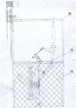
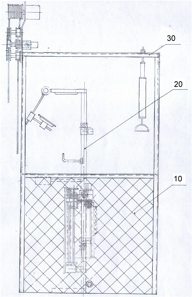
图1为本发明实施例直立式体位结构示意图,1 is a schematic diagram of an upright posture structure according to an embodiment of the present invention,
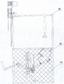
图2为本发明实施例平躺式体位结构示意图,FIG. 2 is a schematic diagram of a lay-flat body position structure according to an embodiment of the present invention,
图3为本发明实施例坐便式体位结构示意图,FIG. 3 is a schematic structural diagram of a toilet seat position according to an embodiment of the present invention,
图4为本发明实施例标准坐姿式体位结构示意图,4 is a schematic diagram of the structure of a standard sitting posture according to an embodiment of the present invention,
图5为本发明实施例安乐椅式体位结构示意图,FIG. 5 is a schematic diagram of the structure of an easy chair type body position according to an embodiment of the present invention,
图6为本发明实施例舒适曲卧式体位结构示意图,6 is a schematic diagram of the structure of the comfortable curved horizontal body position according to the embodiment of the present invention,
图7为本发明实施例左右床帮结构示意图,FIG. 7 is a schematic diagram of the structure of the left and right bed help according to the embodiment of the present invention,
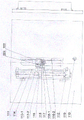
图8为本发明床身结构示意图,Figure 8 is a schematic diagram of the structure of the bed of the present invention,
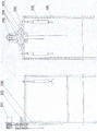
图9为本发明康复支架结构示意图。FIG. 9 is a schematic structural diagram of the rehabilitation stent of the present invention.
图中:10-左右床帮;20-床身;30-康复组合支架;100-落地支柱;110-床帮主板;111-直线滑动导轨;112-1号电机及蜗轮减速机;113-1-螺杆;113-2-螺母;114-圆柱导轨;115-上下升降平台;116-1齿轮,116-2齿条;117-双头齿轮轴;118-带座轴承;119-拉撑组合件;210-第一床身段;211-床头护板;212-3号电机及蜗轮减速机;213-第一床身段的转动连接轴;214-LED无影光源;215-多媒体视屏;220-第二床身段;221-腋下安全保护杆;222-2号电机及蜗轮减速机;223-中轴;230-第三床身段; 231-过渡接口;232-4号电机及蜗轮减速机;233-第三床身段的转动连接轴;234-柔性集便袋;240--第四段床身;241-床脚护板;242-5号电机及蜗轮减速机;243-第四床身段的转动连接轴; 320-手臂拉力器;330-双腿被动拉升锻炼器具及机座;331-6号伺服数控正反转电机;332-吊绳槽轮;333-7号电机及蜗轮减速机组成正反牙螺杆调节吊绳有效长度机构;334-吊绳导向滑轮;335-调节吊绳有效长度滑轮;336-吊绳。In the picture: 10-left and right bed help; 20-bed body; 30-rehabilitation combination bracket; 100-floor support; 110-bed help mainboard; 111-linear sliding guide rail; 112-1 motor and worm gear reducer; 113-1 -Screw; 113-2-nut; 114-cylindrical guide rail; 115-up and down lifting platform; 116-1 gear, 116-2 rack; 117-double-head gear shaft; 118-bearing with seat; 119-bracing assembly ;210-The first bed section; 211-Bed headboard; 212-No.3 motor and worm gear reducer; 213-The rotating connecting shaft of the first bed section; 214-LED shadowless light source; 215-Multimedia video screen; 220- The second bed section; 221-armpit safety rod; 222-No.2 motor and worm gear reducer; 223-Central shaft; 230-The third bed section; 231-Transition interface; 232-No.4 motor and worm gear reducer; 233-The rotating connecting shaft of the third bed section; 234-Flexible toilet bag; 240-The fourth bed section; 241-Bed foot guard; 242-No.5 motor and worm gear reducer; 243-The fourth bed section 320-arm tensioner; 330- double-leg passive lifting exercise equipment and base; 331-6 servo numerical control forward and reverse motor; 332-sling sheave; 333-7 motor and worm gear reducer It is composed of positive and negative screw rod to adjust the effective length of the hanging rope; 334-slinging rope guide pulley; 335-adjusting the effective length of the hanging rope pulley; 336-slinging rope.
具体实施方式Detailed ways
下面结合附图及实施例对本发明做进一步说明。The present invention will be further described below with reference to the accompanying drawings and embodiments.
应该指出,以下详细说明都是示例性的,旨在对本申请提供进一步的说明。除非另有指明,本文使用的所有技术和科学术语具有与本申请所属技术领域的普通技术人员通常理解的相同含义。It should be noted that the following detailed description is exemplary and intended to provide further explanation of the application. Unless otherwise defined, all technical and scientific terms used herein have the same meaning as commonly understood by one of ordinary skill in the art to which this application belongs.
需要注意的是,这里所使用的术语仅是为了描述具体实施方式,而非意图限制根据本申请的示例性实施方式。如在这里所使用的,除非上下文另外明确指出,否则单数形式也意图包括复数形式,此外,还应当理解的是,当在本说明书中使用术语“包含”和/或“包括”时,其指明存在特征、步骤、操作、器件、组件和/或它们的组合。It should be noted that the terminology used herein is for the purpose of describing specific embodiments only, and is not intended to limit the exemplary embodiments according to the present application. As used herein, unless the context clearly dictates otherwise, the singular is intended to include the plural as well, furthermore, it is to be understood that when the terms "comprising" and/or "including" are used in this specification, it indicates that There are features, steps, operations, devices, components and/or combinations thereof.
如图1-9所示,本实施例提供了一种康复护理床,包括床身20,左右床帮10,以及康复组合支架30,所述床身分为四个床身段组成,从床头开始至床脚方向,分别为第一床身段210、第二床身段220、第三床身段230、第四床身段240;所述床身其每一床身段与相邻床身段两段之间采用铰接的形式相互联接,本装置的铰接形式采用的是轴与销孔挂耳联接形式,使的相邻两段能按轴与销孔为圆心、按所需要的角度转动调节,第二床身段靠近第三床身段处横置有一可承受较高强度的中轴223及连接于中轴两端的上下滑动平台115,该滑动平台115出自于左右两端的直线滑动导轨111上,而两端的直线滑动导轨111竖直排列在左右两侧的床帮主板上,所述左右床帮位于所述床身的左右两侧并安装在康复组合支架的四支落地支柱100上,并隨落地支柱直接落地面;同时两个床帮主板110底部之间通过拉撑组合件119连接,床身上于床头和床脚上分别安装有与床身垂直的床头护板211和床脚护板241;As shown in Figures 1-9, this embodiment provides a rehabilitation nursing bed, including a
本装置中的第一床身段与第二床身段之间的销孔挂耳的连接轴213与第一床身段刚性连接,第二床身段与第三床身段之间的销孔挂耳的连接轴233与第三床身段刚性连接,第三床身段与第四床身段之间的销孔挂耳的连接轴243与第四床身段刚性连接,In this device, the connecting
中轴与第二床身段刚性联接,由于中轴处于整体床身的中枢位置,所以动中轴即可动整体床身,中轴除了要承担整体床身重量外还要承担人体的重量,除此之外中轴的主要任务要负责整体床身按照所需要的角度转动以及所需要的高低位置作上下直线滑动;The central axis is rigidly connected with the second bed section. Since the central axis is at the central position of the overall bed, the entire bed can be moved by moving the central axis. In addition to bearing the weight of the overall bed, the central axis also bears the weight of the human body. In addition, the main task of the central axis is to be responsible for the overall bed rotation according to the required angle and the required high and low positions to slide up and down in a straight line;
各床身段长短不一样,根据人类生理结构与生活活动姿态,确定各段长度:第一床身段对应人体从头顶至肩部,第二床身段对应人体从肩部至尾椎骨,第三床身段对应人体从尾椎骨至膝盖,第四床身段对应人体从膝盖至脚底,其各段长度直接来自于使用者的身体高度,根据不同身高的,现提供身高与各段床身长度规格参考表,见下图。The length of each bed body is different. According to the human physiological structure and the posture of life activities, the length of each segment is determined: the first bed body segment corresponds to the human body from the top to the shoulder, the second bed body segment corresponds to the human body from the shoulder to the coccyx, and the third bed body segment corresponds to the human body from the shoulder to the coccyx. Corresponding to the human body from the coccyx to the knee, and the fourth bed section corresponds to the human body from the knee to the sole of the foot. The length of each section is directly derived from the height of the user's body. According to different heights, a reference table of height and length of each section of the bed is provided. See below.
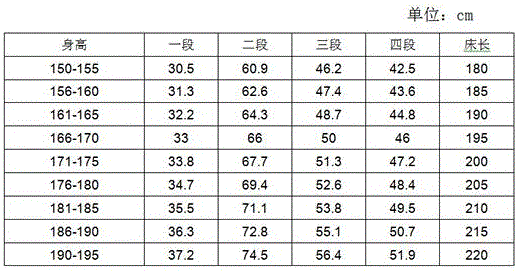
说明:表中第一床身段与第四床身段已经另加10cm用于头顶与脚底的活动空间。Note: The first bed body and the fourth bed body in the table have added 10cm for the activity space on the top of the head and the bottom of the feet.
在本实施例中,所述左右两侧床帮主板的外侧面上互为对称的各装配一套竖直排列的直线滑动导轨111,以及与该直线滑动导轨的平行距离处各装置一条齿条116-2,位于所述直线滑动导轨与所述齿条的之间开设有一条与直线滑动导轨以及齿条相同长度的长形通孔,所述长形通孔用于中轴贯穿左右床帮,并使中轴两端分别支撑在两侧直线滑动导轨的上下滑动平台115上,以及相同的目的长形通孔还需要贯穿一支不可或缺的,能够达到左右床身始终保持左右水平的机械同步与自锁作用的双头齿轮轴117,所述双头齿轮轴117两端除了装置相同模数与相同齿数的齿轮116-1外,还需要各连接一只相同规格的带座轴承118,该带座轴承分别固定在两侧直线滑动导轨的上下滑动平台115底板下方,其两端的齿轮116-1分别与所述的齿条116-2达到同步啮合。完成上述的装置之后可以实现:第一,双头齿轮轴两端的齿轮与齿条一旦定位啮合,就已经实现主动侧的直线上下滑动平台与被动侧的直线上下滑动平台产生了联动,主从两侧形成一体并在同一水平面上,所述定位啮合即是齿轮齿条在啮合固定安装时必须注意到左右两侧直线上下滑动平台的水平面一致方可定位固定。第二,左右两侧直线上下滑动平台一旦定位啮合,从动侧的自锁也随着主动侧的自锁而得到同样的自锁。In this embodiment, a set of vertically arranged linear sliding
在本实施例中,所述四个床身段分别具有五台电机独立驱动,具体为:编号为1号的电机及蜗轮减速机112安装于左右两个直线滑动导轨上的其中一个直线滑动导轨的底端,安装有编号为1号的电机及蜗轮减速机的直线升降滑动导轨为主动侧,另一侧为从动侧,主动侧的直线滑动导轨是现有的螺杆螺母升降机构,螺杆螺母升降机构采用的是螺杆113-1与螺母113-2机构,编号为1号的电机及蜗轮减速机用于驱动螺杆带动螺母再带动上下滑动平台作上下滑动,进而通过双头齿轮轴的同步运行带动整体床身作上下整体滑动,从动侧的直线滑动导轨仅是普通的圆柱滑轨114,其上下滑动平台直接由双头齿轮轴运转而驱动,编号为2号的电机及蜗轮减速机222安装于直线升降滑动导轨任一侧上下滑动平台上,用于驱动中轴的任一端旋转,进而通过中轴带动第二床身段辐射整体床身作角度转动调节,编号为3号的电机及蜗轮减速机212安装于第二床身段的边框,其输出端对准第一床身段内的转动连接轴213的轴心线并与之相连接,用于带动第一床身段作相对第二床身段的角度调节,编号为4号的电机及蜗轮减速机232安装于第二床身段的边框,其输出端对准第三床身段内的转动连接轴233的轴心线并与之相连接,用于带动第三床身段作相对第二床身段的角度调节,编号为5号的电机及蜗轮减速机242安装于第三床身段的边框,其输出端对准第四床身段内的转动连接轴243的轴心线并与之相连接,用于带动第四床身段作相对第三床身段的角度调节,调节方式与第一床身段与第二床身段之间的角度调节方式相同,达到了每一段床身都能有独立电动调节的自由角度,组合起来能够完成各段床身所需的相对角度,达到使用目的。In this embodiment, the four bed sections are independently driven by five motors, specifically: the motor numbered No. 1 and the
本实施例中具体的中轴的运动方法为:编号为1号的电机及蜗轮减速机驱动主动侧的螺杆转动,进而带动螺母上下滑移,再带动上下滑动平台作上下滑动,同时中轴的两端贯穿长形通孔伸出左右床帮,其中一端与2号电机及蜗轮减速器联接,并支撑固定在任一端的直线滑动导轨的上下滑动平台上,中轴的另一端安装有带座轴承固定在其余一端的直线滑动导轨的上下滑动平台上,当然有机械基础的人都知道,安装的要求必须是,中轴两端的中心线距离两端升降平台表面高度一致,而两端的升降平台在两端的齿轮齿条啮合之后保持水平,中轴就必然水平,以上装置既实现了中轴的上下滑动,也实现了中轴的角度转动,还有实现了中轴的永远水平,保证了床身永远保持左右水平状态,既可靠又安全适用,其中要求双头齿轮轴的两端分别都要安装有相同规格的带座轴承各一只,以及相同模数与相同齿数的齿轮各一个,其中齿轮安装在轴的外端头位置,带座轴承安装在齿轮的内侧位置。The specific movement method of the central axis in this embodiment is as follows: the motor numbered No. 1 and the worm gear reducer drive the screw on the active side to rotate, and then drive the nut to slide up and down, and then drive the up and down sliding platform to slide up and down, while the central axis The two ends extend through the long through holes and extend out of the left and right bed help, one end of which is connected with the No. 2 motor and the worm gear reducer, and is supported and fixed on the upper and lower sliding platforms of the linear sliding guide rails at either end, and the other end of the central shaft is installed with a seat bearing. It is fixed on the upper and lower sliding platforms of the linear sliding guides at the other end. Of course, anyone with a mechanical foundation knows that the installation requirements must be that the centerline at both ends of the central axis is at the same height from the surface of the lifting platform at both ends, and the lifting platforms at both ends are at the same height. After the racks and pinions at both ends are meshed and kept horizontal, the central axis must be horizontal. The above device not only realizes the up and down sliding of the central axis, but also realizes the angular rotation of the central axis, and also realizes the permanent level of the central axis, ensuring the bed. Always keep the left and right horizontal state, which is reliable and safe. It is required that both ends of the double-ended gear shaft must be installed with one bearing with the same specification, and one gear with the same module and the same number of teeth. It is installed at the outer end of the shaft, and the housed bearing is installed at the inner position of the gear.
在本实施例中,水平自锁来自三个方面:1、主动侧直线滑动导轨的蜗轮减速机选择有自锁能力;2、主动侧直线滑动导轨的螺杆与螺母具有自锁能力,3、由于主动侧有以上双重保险的自锁能力,所以本装置进一步采用了双头齿轮轴的齿轮齿条联动方式,实质上是将被动侧的自锁通过齿轮齿条的啮合传递至主动端,由于主动侧的自锁使得被动侧得到了自锁。In this embodiment, the horizontal self-locking comes from three aspects: 1. The worm gear reducer of the linear sliding guide on the active side is selected to have self-locking ability; 2. The screw and nut of the linear sliding guide on the active side have self-locking ability; 3. Because The active side has the self-locking ability of the above double insurance, so the device further adopts the rack-and-pinion linkage method of the double-ended gear shaft, which essentially transfers the self-locking of the passive side to the active side through the meshing of the rack and pinion. The self-locking of the side makes the passive side self-locking.
在本实施例中,所述康复组合支架.附图2、附图9上位于床头双臂位置上方的组合支架上,安装有左右两支可调拉力的手臂拉力器320,用于平躺康复护理床时手臂主动拉力锻炼,所述可调拉力是调整拉力器管内拉簧的根数或调整每根拉簧的拉力大小,以达到所需要的拉力的普通拉力器;所述康复组合支架上位于床脚双腿位置上方的支架上,安装有双腿一上一下互为交叉被动拉升锻炼器具及机座330,该机座上安装有吊绳槽轮332、用于驱动吊绳槽轮的6号伺服数控正反转电机331、以及吊绳导向滑轮组334,吊绳槽轮上缠绕有吊绳336,吊绳槽轮上带有螺纹槽,所述螺纹形吊绳槽轮的有效吊绳缠绕圈数的中心点处,必须将吊绳与槽轮作有效的定位,具体方法可用螺钉将吊绳定位在槽轮的螺纹槽内,用以防止吊绳与槽轮滑动位移,影响双腿平衡协调的运动。除上述之外,机座上还装有7号电机及蜗轮减速机及正反牙丝杆333,用于拉开与收近吊绳导向滑轮335,目的为了调节吊绳有效长度,进而达到调节双脚的起始位置,是比较重要的调节手段。In this embodiment, the combination support for rehabilitation. Figures 2 and 9 are installed on the combined support above the double-arm position at the head of the bed. Two left and
正反转电机使得带螺纹槽的吊绳槽轮在正反转过程,吊绳两端等量一上一下,其一上一下速度由电机频率可调,其牵升高度由电机的正反转圈数可调,其一上一下双腿的起始位置由吊绳起始位置,即通过7号电机及蜗轮减速机及正反牙丝杆333驱动螺杆调节移动滑轮,用于拉开与收近吊绳导向滑轮335,可延伸或收缩吊绳的有效长度用以达到双腿合适的起始位置,其速度由频率可调,其牵升高度采用调整正反转电机的正反转圈数,上述物理调节与电气调节双作用下,达到可调双腿的拉升高度与提升速度和双腿的起始位置,目的为了促进血液循环,预防肌肉萎缩,并能增强肌体免疫力,促进康复。The forward and reverse motor makes the rope sheave with threaded grooves in the forward and reverse process, the two ends of the rope go up and down equally, the speed of one up and down is adjustable by the frequency of the motor, and its pulling height is determined by the positive and negative rotation of the motor. The number can be adjusted, the starting position of the upper and lower legs is the starting position of the hanging rope, that is, the moving pulley is adjusted by the No. 7 motor, the worm gear reducer and the positive and
在本实施例中,所述第三床身段设置有标准坐便器,所述标准坐便器包括坐便圈、柔性集便袋234,以及该坐便圈与柔性集便袋之间装置有过渡接口231,该过渡接口采用不锈钢材料,冲压成成如图8所示的圆锥形加圆柱形接口,圆柱形接口处有个外翻的凸台止口,用以防止柔性集便袋下滑脱落,所述柔性集便袋采用双层结构,内层采用一次性可降解塑料袋,外层采用适当厚度的纺织类布料,袋口缝有穿绳圈或松紧带圈,合适的袋子直径以及合适的长度即可,外袋可作重复使用,使用时塑料袋套入布料的外袋内,注意事项是塑料袋要长出外袋一定的长度,以免外袋被玷污,所述系挂本发明专用的柔性集便袋,是指图3所述的柔性集便袋系挂在图8所述的坐便器的过渡接口上。所述坐便器可作高端配置,比如配置有自动热水冲洗及热风吹干等,过渡接口开设于第三床身段上。坐便完毕之后卸下柔性集便袋,取出内袋作无公害化处理,外袋可作重复的使用。In this embodiment, the third bed section is provided with a standard toilet, the standard toilet includes a toilet ring, a
在本实施例中,所述第二床身段设置有腋下安全保护杆221,所述腋下安全保护杆位于胸部的左右两侧,高低靠近腋下的位置,保护杆底部设置有横向滑轨,滑槽设置在床身底板上,滑槽长度直至左右的边框为止,在滑轨上表面固定有钢管弯曲成倒L字形的安全保护杆,可适合人工推拉动作,不用时两边保护杆可推至床边框止,使用时拉近靠紧胸部,双臂夹紧保护杆,倒L字形能够勾住腋下至肩膀,该保护杆主要用于床身翻转时使用,比如:从其它体位转换成站立体位,或从站立体位转换至其它体位时,都适合使用安全保护杆。In this embodiment, the second bed section is provided with underarm
在本实施例中,所述第一床身段的床头护板上设置有可调视距的多媒体视屏215以及一对LED无影光源214。In this embodiment, a
所述直立式体位,详见附图1,设计直立式体位主要为了能够解决两个大难题:The upright posture is shown in Figure 1 for details. The upright posture is designed to solve two major problems:
第一、是为了解决病人的上床与下床,特别对于行动不能自理的病人,上床与下床都十分困难,常见有两三人参扶抱病人上床或抱病人下床的场景,设计了直立式体位就方便了许多,比如上床,使用时将床身设至直立式体位,病人背对床身向后退一步,脚踩床脚护板、背部紧靠床身,接下来首先先将设置于腋下位于胸部左右两侧的腋下安全保护杆拉近靠紧胸部两侧,(该装置可以横向平移拉动),将双臂夹紧与双手抓紧安全保护杆,视病人自知能力情况,必要时为了更安全也可以用绳带将身体与安全保护杆捆在一块。即可点触触摸屏的平躺式体位,床身开始从直立式体位,向后翻转90度床身变成平躺式体位,此时病人已经完成上床平躺于平躺式体位;下床与上床同样方便,作相同顺序的逆向操作即完成所谓的向前一步就脚踏地面完成了下床。First, in order to solve the problem of getting into and out of bed for patients, especially for patients who cannot take care of themselves, it is very difficult to get in and out of bed. It is common for two or three people to help the patient to go to bed or get out of bed, so the upright type is designed. The body position is much more convenient. For example, when going to bed, set the bed to an upright position. The patient takes a step back with his back to the bed, his feet are on the foot guards of the bed, and his back is close to the bed. Next, first set it in the armpit. The lower armpit safety bars located on the left and right sides of the chest are pulled close to both sides of the chest (the device can be pulled horizontally), and the arms are clamped and the hands are grasped on the safety bars. Depending on the patient's self-awareness, if necessary For extra safety, the body and the safety bar can also be tied together with a rope strap. You can touch the flat-lying position on the touch screen, the bed starts to change from the upright position, and the bed is turned back 90 degrees to become the flat-lying position. It is also convenient to go to bed. Do the reverse operation of the same sequence to complete the so-called step forward, then step on the ground and get out of bed.
第二、是为了隨床实现可(拉、撒),即隨床实现坐便,直立式体位是便前与便后的准备工作所必须的体位,便前需要直立式体位完成的准备工作有:1、松衣解裤,2、取下位于坐便器之上的床垫,露出坐便器的坐便圈,3、系挂柔性集便袋,三项工作完成了便前的准备工作,即可以点触触摸屏的坐便式体位,详见附图3,床身随之开始变位,人体只须背部紧靠床身,随床身变动就自然而然被动的变成为坐姿、坐在坐便器坐便圈上实现随床坐便;便后床身需要再回到直立式体位完成便后三项工作:1、整装衣裤、2、恢复被取下的床垫,3、取下柔性集便袋,完成随床坐便全过程。Second, in order to achieve (pulling, spreading) with the bed, that is, to achieve toilet sitting with the bed, the upright posture is a necessary posture for the preparations before and after the toilet. The preparations that need to be completed in the upright posture before the toilet are : 1. Loosen clothes and trousers, 2. Take off the mattress above the toilet to expose the toilet seat of the toilet, 3. Tie the flexible toilet bag, three tasks have completed the preparatory work, namely The sitting posture can be touched by touching the touch screen, see Figure 3 for details, the bed will start to change position, the human body only needs to be close to the bed with the back, and it will automatically become a sitting posture, sitting on the toilet as the bed changes. The toilet seat can be used to sit with the bed; after the toilet, the bed needs to return to the upright position to complete the three tasks after the toilet: 1. Putting on the clothes, 2. Restoring the removed mattress, 3. Removing the flexible Set the toilet bag to complete the whole process of sitting on the bed.
进一步的,所述标准坐姿式体位,详见附图4,是为了实现隨床吃、喝、工作、写字、以及看多媒体视频,该体位还须配套一个桌面板,可以采用固定在床帮边缘以铰链结构翻转上来成为桌面,也可以附带一块桌面板需要时放上,不用时取下,因均为通常事项,故未在附图4中体现。Further, the standard sitting posture, as shown in Figure 4, is to achieve eating, drinking, working, writing, and watching multimedia videos with the bed. This posture must also be equipped with a desktop board, which can be fixed on the edge of the bed. It can be turned up to form a desktop with a hinge structure, and a desktop board can also be attached when needed, and removed when not in use. Since it is a common matter, it is not shown in Figure 4.
进一步的,所述安乐椅式体位,详见附图5,是人们最喜欢的休闲坐姿,它减轻腰部承载力,将人体的重心分布到背部负担,最适合看书、读报、喝吸管饮料,以及看多媒体视频,能感受到轻松且心情惬意。Further, the easy chair posture, see attached drawing 5 for details, is the most popular leisure sitting posture, it reduces the bearing capacity of the waist, distributes the center of gravity of the human body to the back burden, and is most suitable for reading, reading newspapers, drinking straw beverages, And watching multimedia videos, you can feel relaxed and comfortable.
进一步的,所述舒适曲卧式体位,详见附图6,人们喜欢的一种非正式的睡姿,一种小憩,一种放松浏览刷手机以及看多媒体视频的体位,除此之外还可有自定义体位,可作自行随意调节。Further, the comfortable curved lying posture, see Figure 6 for details, an informal sleeping posture that people like, a kind of nap, a posture for relaxing browsing, swiping mobile phones and watching multimedia videos, in addition to It can have a custom body position, which can be adjusted at will.
本装置根据人类的生理结构与人类的生活与活动姿态,设计的各种体位的变换,并在变换过程、与人类的身体变形动作一致,所以不会伤及床上病人,真正意义上做到了随床变换体位的目的。According to the human physiological structure and human life and activity posture, this device designs the transformation of various body positions, and in the transformation process, it is consistent with the human body deformation action, so it will not hurt the patient in bed, and in a real sense, it can follow The purpose of changing the position of the bed.
本装置改变了行动有困难的病人在治疔或在康复过程,长时间平躺在病床那种特别累与特别乏味的辛苦,真正意义上做到了需要时能够隨床变换体位,对病人的治病与康复期间的生话质量都很重要,除此之外本发明附带有康复器材,对病人的康复护理质量意义重大。The device has changed the particularly tiring and tedious hard work of lying on the bed for a long time in the process of treating boils or in the recovery process of patients with difficulty in moving. The quality of speech during illness and recovery is very important. In addition, the present invention is accompanied by rehabilitation equipment, which is of great significance to the quality of the patient's rehabilitation care.
本实施例中,所述的电机及蜗轮减速机是本发明指定选择的配套传动机械,目的是为了使所有床身在任何体位时都不允许有滑位现象,这就需要电机或减速机有自锁功能,为了床身的安全,本发明选择螺旋角小、摩擦角小、转速比大的单头蜗杆蜗轮减速机,有足够强大的自锁能力,完全可以保证所有床身在任何体位时的自锁。In this embodiment, the motor and the worm gear reducer are the supporting transmission machinery designated and selected by the present invention. Self-locking function, for the safety of the bed, the present invention selects a single-head worm gear reducer with a small helix angle, a small friction angle, and a large rotational speed ratio, which has a strong enough self-locking ability and can completely ensure that all the beds are in any position. self-locking.
上述本发明所公开的任一技术方案除另有声明外,如果其公开了数值范围,那么公开的数值范围均为优选的数值范围,任何本领域的技术人员应该理解:优选的数值范围仅仅是诸多可实施的数值中技术效果比较明显或具有代表性的数值。由于数值较多,无法穷举,所以本发明才公开部分数值以举例说明本发明的技术方案,并且,上述列举的数值不应构成对本发明创造保护范围的限制。Unless otherwise stated in any of the technical solutions disclosed in the present invention, if it discloses a numerical range, then the disclosed numerical range is a preferred numerical range, and any person skilled in the art should understand that: the preferred numerical range is only Among the many implementable numerical values, the technical effect is relatively obvious or representative. Since the numerical values are too numerous to be exhaustive, only some numerical values are disclosed in the present invention to illustrate the technical solutions of the present invention, and the above-mentioned numerical values shall not constitute a limitation on the protection scope of the present invention.
如果本文中使用了“第一”、“第二”等词语来限定零部件的话,本领域技术人员应该知晓:“第一”、“第二”的使用仅仅是为了便于描述上对零部件进行区别如没有另行声明外,上述词语并没有特殊的含义。If words such as "first" and "second" are used herein to define components, those skilled in the art should know that the use of "first" and "second" is only for the convenience of describing components The above terms have no special meaning unless otherwise stated.
本发明如果公开或涉及了互相固定连接的零部件或结构件,那么,除另有声明外,固定连接可以理解为:能够拆卸地固定连接( 例如使用螺栓或螺钉连接),也可以理解为:不可拆卸的固定连接(例如铆接、焊接),当然,互相固定连接也可以为一体式结构( 例如使用铸造工艺一体成形制造出来) 所取代(明显无法采用一体成形工艺除外)。If the present invention discloses or involves parts or structures that are fixedly connected to each other, then, unless otherwise stated, fixed connection can be understood as: detachable fixed connection (for example, using bolts or screws), can also be understood as: Non-removable fixed connections (such as riveting, welding), of course, mutual fixed connections can also be replaced by a one-piece structure (for example, integrally formed using a casting process) (except that it is obviously impossible to use a one-piece forming process).
另外,上述本发明公开的任一技术方案中所应用的用于表示位置关系例如“纵向”、“横向”、“上”、“下”、“前”、“后”、“左”、“右”、“竖直”、“水平”、“顶”、“底”、“内”、“外”等指示的方位或位置关系为基于附图所示的方位或位置关系,仅是为了便于描述本专利,而不是指示或暗示所指的装置或元件必须具有特定的方位、以特定的方位构造和操作,因此不能理解为对本专利的限制,且上述本发明公开的任一技术方案中所应用的用于表示形状的术语除另有声明外其含义包括与其近似、类似或接近的形状。In addition, any of the above-mentioned technical solutions disclosed in the present invention are used to represent positional relationships such as "vertical", "horizontal", "top", "bottom", "front", "rear", "left", " The orientation or positional relationship indicated by "right", "vertical", "horizontal", "top", "bottom", "inside", "outside", etc. is based on the orientation or positional relationship shown in the drawings, and is only for convenience Describe this patent, rather than indicating or implying that the referred device or element must have a specific orientation, be constructed and operated in a specific orientation, so it cannot be construed as a limitation on this patent, and any of the technical solutions disclosed in the present invention mentioned above Terms used to refer to shapes are used in their meanings to include shapes that are close to, similar to, or close to, unless otherwise stated.
本发明提供的任一部件既可以是由多个单独的组成部分组装而成,也可以为一体成形工艺制造出来的单独部件。Any component provided by the present invention may be assembled from a plurality of individual components, or may be a single component manufactured by an integral molding process.
最后应当说明的是:以上实施例仅用以说明本发明的技术方案而非对其限制;尽管参照较佳实施例对本发明进行了详细的说明,所属领域的普通技术人员应当理解:依然可以对本发明的具体实施方式进行修改或者对部分技术特征进行等同替换;而不脱离本发明技术方案的精神,其均应涵盖在本发明请求保护的技术方案范围当中。Finally it should be noted that: the above embodiment is only used to illustrate the technical scheme of the present invention and not to limit it; Although the present invention has been described in detail with reference to the preferred embodiment, those of ordinary skill in the art should understand: The specific embodiments of the invention are modified or some technical features are equivalently replaced; without departing from the spirit of the technical solutions of the present invention, all of them should be included in the scope of the technical solutions claimed in the present invention.
Claims (9)
Priority Applications (1)
| Application Number | Priority Date | Filing Date | Title |
|---|---|---|---|
| CN202210759840.0A CN115006135A (en) | 2022-06-30 | 2022-06-30 | A kind of rehabilitation nursing bed |
Applications Claiming Priority (1)
| Application Number | Priority Date | Filing Date | Title |
|---|---|---|---|
| CN202210759840.0A CN115006135A (en) | 2022-06-30 | 2022-06-30 | A kind of rehabilitation nursing bed |
Publications (1)
| Publication Number | Publication Date |
|---|---|
| CN115006135A true CN115006135A (en) | 2022-09-06 |
Family
ID=83079741
Family Applications (1)
| Application Number | Title | Priority Date | Filing Date |
|---|---|---|---|
| CN202210759840.0A Pending CN115006135A (en) | 2022-06-30 | 2022-06-30 | A kind of rehabilitation nursing bed |
Country Status (1)
| Country | Link |
|---|---|
| CN (1) | CN115006135A (en) |
Citations (8)
| Publication number | Priority date | Publication date | Assignee | Title |
|---|---|---|---|---|
| US20090151074A1 (en) * | 2002-03-18 | 2009-06-18 | Paramount Bed Co., Ltd. | Coordinative Control Method For Adjusting The Back and Knee Bottom Sections Of An Adjustable Bed, And Computer Program For Implementing Same |
| WO2014115994A1 (en) * | 2013-01-24 | 2014-07-31 | Bae Duke | Chiropractic and paraspinal muscle strengthening exercise apparatus |
| CN204121322U (en) * | 2014-09-17 | 2015-01-28 | 合儒从 | A kind of family rehabilitation nursing bed |
| CN107303229A (en) * | 2016-04-19 | 2017-10-31 | 杨俊丽 | A kind of self-service sliding Height-adjustable |
| CN209154294U (en) * | 2018-11-02 | 2019-07-26 | 常州工程职业技术学院 | A kind of wheelchair combined multi-functional nursing bed |
| CN111921160A (en) * | 2020-08-21 | 2020-11-13 | 李骄阳 | Paediatrics is with recovered nursing device of taking exercise |
| CN113274247A (en) * | 2020-05-28 | 2021-08-20 | 首都医科大学宣武医院 | Rehabilitation training device |
| CN216652700U (en) * | 2021-10-18 | 2022-06-03 | 南通双辉医疗器械科技有限公司 | Medical care bed with rehabilitation training function |
-
2022
- 2022-06-30 CN CN202210759840.0A patent/CN115006135A/en active Pending
Patent Citations (8)
| Publication number | Priority date | Publication date | Assignee | Title |
|---|---|---|---|---|
| US20090151074A1 (en) * | 2002-03-18 | 2009-06-18 | Paramount Bed Co., Ltd. | Coordinative Control Method For Adjusting The Back and Knee Bottom Sections Of An Adjustable Bed, And Computer Program For Implementing Same |
| WO2014115994A1 (en) * | 2013-01-24 | 2014-07-31 | Bae Duke | Chiropractic and paraspinal muscle strengthening exercise apparatus |
| CN204121322U (en) * | 2014-09-17 | 2015-01-28 | 合儒从 | A kind of family rehabilitation nursing bed |
| CN107303229A (en) * | 2016-04-19 | 2017-10-31 | 杨俊丽 | A kind of self-service sliding Height-adjustable |
| CN209154294U (en) * | 2018-11-02 | 2019-07-26 | 常州工程职业技术学院 | A kind of wheelchair combined multi-functional nursing bed |
| CN113274247A (en) * | 2020-05-28 | 2021-08-20 | 首都医科大学宣武医院 | Rehabilitation training device |
| CN111921160A (en) * | 2020-08-21 | 2020-11-13 | 李骄阳 | Paediatrics is with recovered nursing device of taking exercise |
| CN216652700U (en) * | 2021-10-18 | 2022-06-03 | 南通双辉医疗器械科技有限公司 | Medical care bed with rehabilitation training function |
Similar Documents
| Publication | Publication Date | Title |
|---|---|---|
| US9492339B2 (en) | Chair, frame and lifting garment useful for patients | |
| TWI450712B (en) | Apparatus for turning over and transferring patient | |
| CN209137138U (en) | It is nursing hospital bed | |
| JPH04288160A (en) | Bed apparatus and attachment for rehabilitation | |
| CN102824254A (en) | Auxiliary nursing moving and taking device | |
| CN202802005U (en) | Auxiliary nursing transfer device | |
| CN103405316A (en) | Multifunctional sickbed | |
| CN112245154A (en) | Novel multi-functional flexible nursing bed | |
| KR100887411B1 (en) | Semi-Automatic Medical Bed | |
| KR20190022222A (en) | A health bed system having a exercise assistance aids | |
| CN107049652A (en) | One kind can it is electronic can singlehanded self-help insurance rise and sit massage and help just anal cleaning moving bed | |
| CN201987781U (en) | Nursing bed for helping people to have natural sitting posture | |
| CN108814849A (en) | A kind of tumor patient foldable multifunctional Restoring nursing bed | |
| CN102125490B (en) | Nursing bed assisting people in natural sitting posture | |
| CN104721011A (en) | Multidimensional lower-limb rehabilitation training robot | |
| CN202314005U (en) | Electric multifunctional nursing bed | |
| CN113384774B (en) | Medical multifunctional transfusion chair | |
| CN213311014U (en) | Multifunctional medical nursing wheelchair | |
| CN214763131U (en) | Recovered device of taking exercise of child's nursing shank | |
| CN115024904A (en) | Wheelchair with self-service wearing and taking-off assisting function | |
| CN209422317U (en) | A kind of medical treatment auxiliary shifting machine | |
| CN214259718U (en) | A medical folding bed | |
| CN213883916U (en) | A bed and chair integrated sleep care device | |
| CN220089818U (en) | Nursing bed with sitting and standing supporting function | |
| CN105434125B (en) | Self-service turn guardrail and pad and its application method |
Legal Events
| Date | Code | Title | Description |
|---|---|---|---|
| PB01 | Publication | ||
| PB01 | Publication | ||
| SE01 | Entry into force of request for substantive examination | ||
| SE01 | Entry into force of request for substantive examination | ||
| TA01 | Transfer of patent application right | ||
| TA01 | Transfer of patent application right |
Effective date of registration: 20230630 Address after: Room 701, Building 2, No. 20, Jinquan Road, Gulou District, Fuzhou City, Fujian Province, 350001 Applicant after: Xie Kaixing Address before: Room 701, Building 2, No. 20, Jinquan Road, Gulou District, Fuzhou City, Fujian Province, 350001 Applicant before: Xie Kaixing Applicant before: Zhang Hui |