CN114985943A - Solar laser processing equipment and method - Google Patents
Solar laser processing equipment and method Download PDFInfo
- Publication number
- CN114985943A CN114985943A CN202210924961.6A CN202210924961A CN114985943A CN 114985943 A CN114985943 A CN 114985943A CN 202210924961 A CN202210924961 A CN 202210924961A CN 114985943 A CN114985943 A CN 114985943A
- Authority
- CN
- China
- Prior art keywords
- laser processing
- buffer
- discharging
- materials
- feeding
- Prior art date
- Legal status (The legal status is an assumption and is not a legal conclusion. Google has not performed a legal analysis and makes no representation as to the accuracy of the status listed.)
- Granted
Links
- 238000012545 processing Methods 0.000 title claims abstract description 99
- 238000000034 method Methods 0.000 title claims description 8
- 239000000463 material Substances 0.000 claims abstract description 390
- 238000004519 manufacturing process Methods 0.000 claims abstract description 42
- 239000012634 fragment Substances 0.000 claims abstract description 22
- 238000001514 detection method Methods 0.000 claims abstract description 18
- 238000003672 processing method Methods 0.000 claims abstract description 5
- 239000000872 buffer Substances 0.000 claims description 127
- 238000007599 discharging Methods 0.000 claims description 63
- 230000007246 mechanism Effects 0.000 claims description 59
- 239000002994 raw material Substances 0.000 claims description 48
- 230000005540 biological transmission Effects 0.000 claims description 13
- 238000009434 installation Methods 0.000 claims description 10
- 238000007664 blowing Methods 0.000 claims description 6
- 230000002146 bilateral effect Effects 0.000 claims description 4
- 238000003754 machining Methods 0.000 claims description 3
- 230000008569 process Effects 0.000 claims description 3
- 241000252254 Catostomidae Species 0.000 claims 7
- 230000003139 buffering effect Effects 0.000 abstract description 4
- 230000009286 beneficial effect Effects 0.000 abstract description 2
- 230000006872 improvement Effects 0.000 description 9
- 238000010586 diagram Methods 0.000 description 5
- 238000003825 pressing Methods 0.000 description 4
- 239000000758 substrate Substances 0.000 description 4
- 239000004579 marble Substances 0.000 description 3
- 230000002745 absorbent Effects 0.000 description 2
- 239000002250 absorbent Substances 0.000 description 2
- 238000005520 cutting process Methods 0.000 description 2
- 230000009977 dual effect Effects 0.000 description 2
- 230000008602 contraction Effects 0.000 description 1
- 238000005260 corrosion Methods 0.000 description 1
- 230000007797 corrosion Effects 0.000 description 1
- 238000013461 design Methods 0.000 description 1
- 230000000694 effects Effects 0.000 description 1
- 230000003028 elevating effect Effects 0.000 description 1
- 230000006870 function Effects 0.000 description 1
- 230000002452 interceptive effect Effects 0.000 description 1
- 239000012160 loading buffer Substances 0.000 description 1
- 238000012423 maintenance Methods 0.000 description 1
- 230000003287 optical effect Effects 0.000 description 1
- 230000008439 repair process Effects 0.000 description 1
- 238000006467 substitution reaction Methods 0.000 description 1
- 238000012546 transfer Methods 0.000 description 1
- 238000013519 translation Methods 0.000 description 1
Images


Classifications
-
- B—PERFORMING OPERATIONS; TRANSPORTING
- B23—MACHINE TOOLS; METAL-WORKING NOT OTHERWISE PROVIDED FOR
- B23K—SOLDERING OR UNSOLDERING; WELDING; CLADDING OR PLATING BY SOLDERING OR WELDING; CUTTING BY APPLYING HEAT LOCALLY, e.g. FLAME CUTTING; WORKING BY LASER BEAM
- B23K26/00—Working by laser beam, e.g. welding, cutting or boring
- B23K26/36—Removing material
-
- B—PERFORMING OPERATIONS; TRANSPORTING
- B23—MACHINE TOOLS; METAL-WORKING NOT OTHERWISE PROVIDED FOR
- B23K—SOLDERING OR UNSOLDERING; WELDING; CLADDING OR PLATING BY SOLDERING OR WELDING; CUTTING BY APPLYING HEAT LOCALLY, e.g. FLAME CUTTING; WORKING BY LASER BEAM
- B23K26/00—Working by laser beam, e.g. welding, cutting or boring
- B23K26/70—Auxiliary operations or equipment
- B23K26/702—Auxiliary equipment
-
- G—PHYSICS
- G01—MEASURING; TESTING
- G01N—INVESTIGATING OR ANALYSING MATERIALS BY DETERMINING THEIR CHEMICAL OR PHYSICAL PROPERTIES
- G01N33/00—Investigating or analysing materials by specific methods not covered by groups G01N1/00 - G01N31/00
-
- H—ELECTRICITY
- H01—ELECTRIC ELEMENTS
- H01L—SEMICONDUCTOR DEVICES NOT COVERED BY CLASS H10
- H01L21/00—Processes or apparatus adapted for the manufacture or treatment of semiconductor or solid state devices or of parts thereof
- H01L21/67—Apparatus specially adapted for handling semiconductor or electric solid state devices during manufacture or treatment thereof; Apparatus specially adapted for handling wafers during manufacture or treatment of semiconductor or electric solid state devices or components ; Apparatus not specifically provided for elsewhere
- H01L21/67005—Apparatus not specifically provided for elsewhere
- H01L21/67242—Apparatus for monitoring, sorting or marking
- H01L21/67259—Position monitoring, e.g. misposition detection or presence detection
-
- H—ELECTRICITY
- H01—ELECTRIC ELEMENTS
- H01L—SEMICONDUCTOR DEVICES NOT COVERED BY CLASS H10
- H01L21/00—Processes or apparatus adapted for the manufacture or treatment of semiconductor or solid state devices or of parts thereof
- H01L21/67—Apparatus specially adapted for handling semiconductor or electric solid state devices during manufacture or treatment thereof; Apparatus specially adapted for handling wafers during manufacture or treatment of semiconductor or electric solid state devices or components ; Apparatus not specifically provided for elsewhere
- H01L21/673—Apparatus specially adapted for handling semiconductor or electric solid state devices during manufacture or treatment thereof; Apparatus specially adapted for handling wafers during manufacture or treatment of semiconductor or electric solid state devices or components ; Apparatus not specifically provided for elsewhere using specially adapted carriers or holders; Fixing the workpieces on such carriers or holders
- H01L21/6732—Vertical carrier comprising wall type elements whereby the substrates are horizontally supported, e.g. comprising sidewalls
-
- H—ELECTRICITY
- H01—ELECTRIC ELEMENTS
- H01L—SEMICONDUCTOR DEVICES NOT COVERED BY CLASS H10
- H01L21/00—Processes or apparatus adapted for the manufacture or treatment of semiconductor or solid state devices or of parts thereof
- H01L21/67—Apparatus specially adapted for handling semiconductor or electric solid state devices during manufacture or treatment thereof; Apparatus specially adapted for handling wafers during manufacture or treatment of semiconductor or electric solid state devices or components ; Apparatus not specifically provided for elsewhere
- H01L21/677—Apparatus specially adapted for handling semiconductor or electric solid state devices during manufacture or treatment thereof; Apparatus specially adapted for handling wafers during manufacture or treatment of semiconductor or electric solid state devices or components ; Apparatus not specifically provided for elsewhere for conveying, e.g. between different workstations
- H01L21/67739—Apparatus specially adapted for handling semiconductor or electric solid state devices during manufacture or treatment thereof; Apparatus specially adapted for handling wafers during manufacture or treatment of semiconductor or electric solid state devices or components ; Apparatus not specifically provided for elsewhere for conveying, e.g. between different workstations into and out of processing chamber
- H01L21/67742—Mechanical parts of transfer devices
-
- H—ELECTRICITY
- H01—ELECTRIC ELEMENTS
- H01L—SEMICONDUCTOR DEVICES NOT COVERED BY CLASS H10
- H01L21/00—Processes or apparatus adapted for the manufacture or treatment of semiconductor or solid state devices or of parts thereof
- H01L21/67—Apparatus specially adapted for handling semiconductor or electric solid state devices during manufacture or treatment thereof; Apparatus specially adapted for handling wafers during manufacture or treatment of semiconductor or electric solid state devices or components ; Apparatus not specifically provided for elsewhere
- H01L21/677—Apparatus specially adapted for handling semiconductor or electric solid state devices during manufacture or treatment thereof; Apparatus specially adapted for handling wafers during manufacture or treatment of semiconductor or electric solid state devices or components ; Apparatus not specifically provided for elsewhere for conveying, e.g. between different workstations
- H01L21/67739—Apparatus specially adapted for handling semiconductor or electric solid state devices during manufacture or treatment thereof; Apparatus specially adapted for handling wafers during manufacture or treatment of semiconductor or electric solid state devices or components ; Apparatus not specifically provided for elsewhere for conveying, e.g. between different workstations into and out of processing chamber
- H01L21/6776—Continuous loading and unloading into and out of a processing chamber, e.g. transporting belts within processing chambers
-
- H—ELECTRICITY
- H01—ELECTRIC ELEMENTS
- H01L—SEMICONDUCTOR DEVICES NOT COVERED BY CLASS H10
- H01L21/00—Processes or apparatus adapted for the manufacture or treatment of semiconductor or solid state devices or of parts thereof
- H01L21/67—Apparatus specially adapted for handling semiconductor or electric solid state devices during manufacture or treatment thereof; Apparatus specially adapted for handling wafers during manufacture or treatment of semiconductor or electric solid state devices or components ; Apparatus not specifically provided for elsewhere
- H01L21/68—Apparatus specially adapted for handling semiconductor or electric solid state devices during manufacture or treatment thereof; Apparatus specially adapted for handling wafers during manufacture or treatment of semiconductor or electric solid state devices or components ; Apparatus not specifically provided for elsewhere for positioning, orientation or alignment
-
- H—ELECTRICITY
- H01—ELECTRIC ELEMENTS
- H01L—SEMICONDUCTOR DEVICES NOT COVERED BY CLASS H10
- H01L31/00—Semiconductor devices sensitive to infrared radiation, light, electromagnetic radiation of shorter wavelength or corpuscular radiation and specially adapted either for the conversion of the energy of such radiation into electrical energy or for the control of electrical energy by such radiation; Processes or apparatus specially adapted for the manufacture or treatment thereof or of parts thereof; Details thereof
- H01L31/18—Processes or apparatus specially adapted for the manufacture or treatment of these devices or of parts thereof
- H01L31/1876—Particular processes or apparatus for batch treatment of the devices
-
- Y—GENERAL TAGGING OF NEW TECHNOLOGICAL DEVELOPMENTS; GENERAL TAGGING OF CROSS-SECTIONAL TECHNOLOGIES SPANNING OVER SEVERAL SECTIONS OF THE IPC; TECHNICAL SUBJECTS COVERED BY FORMER USPC CROSS-REFERENCE ART COLLECTIONS [XRACs] AND DIGESTS
- Y02—TECHNOLOGIES OR APPLICATIONS FOR MITIGATION OR ADAPTATION AGAINST CLIMATE CHANGE
- Y02P—CLIMATE CHANGE MITIGATION TECHNOLOGIES IN THE PRODUCTION OR PROCESSING OF GOODS
- Y02P70/00—Climate change mitigation technologies in the production process for final industrial or consumer products
- Y02P70/50—Manufacturing or production processes characterised by the final manufactured product
Abstract
The invention provides solar laser processing equipment which comprises a feeding device for feeding a flaky material, a feeding alignment device for centrally aligning the flaky material, a feeding cache device for caching the flaky material, a fragment detection device for detecting fragments of the flaky material, a laser processing unit for laser processing the flaky material, a blanking cache device for caching the flaky material, a blanking alignment device for centrally aligning the flaky material and a blanking device for blanking the flaky material, wherein the feeding device for feeding the flaky material, the feeding alignment device for centrally aligning the flaky material, the feeding cache device for caching the flaky material, the blanking cache device for buffering the flaky material, and the blanking cache device for buffering the flaky material are sequentially arranged according to the processing sequence. The invention also provides a solar laser processing method. The invention has the beneficial effects that: the full-automatic laser processing of the flaky materials can be realized, the processing speed is high, the productivity is favorably improved, and the production efficiency is improved.
Description
Technical Field
The invention relates to laser processing equipment, in particular to solar laser processing equipment and a method.
Background
The conventional scribing equipment for the solar substrate is low in automation degree and production efficiency.
Therefore, it is an urgent technical problem to be solved by those skilled in the art to provide a solar laser processing apparatus which can form an assembly line for automatic processing, complete automation and high speed scribing of a solar substrate on the basis of small floor space.
Disclosure of Invention
In order to solve the problems in the prior art, the invention provides solar laser processing equipment and a solar laser processing method.
The invention provides solar laser processing equipment which comprises a feeding device for feeding sheet-shaped materials, a feeding alignment device for centrally aligning the sheet-shaped materials, a feeding cache device for caching the sheet-shaped materials, a fragment detection device for detecting fragments of the sheet-shaped materials, a laser processing unit for laser processing the sheet-shaped materials, a blanking cache device for caching the sheet-shaped materials, a blanking alignment device for centrally aligning the sheet-shaped materials and a blanking device for blanking the sheet-shaped materials, which are sequentially arranged according to the processing sequence, the laser processing unit comprises a double-rotary-disc device and a laser processing device, and the feeding device, the feeding alignment device, the feeding cache device, the fragment detection device, the double-rotary-disc device, the discharging cache device, the discharging alignment device and the discharging device are sequentially butted to form a production line for conveying flaky materials.
As a further improvement of the invention, the solar laser processing equipment has two solar laser processing equipment which are arranged back to back.
As a further improvement of the invention, the direction of conveying the sheet materials by the flow line is the front-back direction, two feeding and discharging devices which are symmetrically arranged front and back respectively form a feeding device and a discharging device, the feeding and discharging device comprises a material frame for placing the sheet materials, a material frame lifting mechanism, a material frame in-place conveying mechanism and a material taking and discharging mechanism, wherein the material frame is arranged on the material frame in-place conveying mechanism, the material frame in-place conveying mechanism is arranged on the material frame lifting mechanism, the material taking and discharging mechanism comprises a material taking and discharging support, a material taking and discharging motor, a material taking and discharging telescopic cylinder and a material taking and discharging telescopic flow line, the material taking and discharging motor, the material taking and discharging telescopic flow line and the material taking and discharging telescopic flow line are respectively arranged on the material taking and discharging support, the material taking and discharging motor is connected with the material taking and discharging telescopic flow line to drive the belt conveying of the material taking and discharging telescopic flow line, get the flexible cylinder of blowing with get the flexible assembly line of blowing and be connected, the drive get the flexible assembly line's of blowing belt flexible.
As a further improvement of the invention, the material taking and placing telescopic assembly line comprises a driving wheel, a first driving wheel, a second driving wheel, a third driving wheel and a belt, the belt is tensioned on the driving wheel, the first driving wheel, the second driving wheel and the third driving wheel, the material taking and placing motor is connected with the driving wheel, the first driving wheel is fixedly arranged on the material taking and placing support, the second driving wheel and the third driving wheel are respectively and fixedly connected with the material taking and placing telescopic cylinder, the material taking and placing telescopic cylinder is connected with a material taking and placing telescopic slider, the material taking and placing telescopic slider is in sliding fit with the material taking and placing support, the second driving wheel and the third driving wheel are respectively and fixedly arranged on the material taking and placing telescopic slider, and the first driving wheel, the second driving wheel and the third driving wheel are sequentially arranged from bottom to top.
As a further improvement of the invention, the direction of conveying the sheet-shaped materials by the assembly line is the front-back direction, the two contraposition devices symmetrically arranged in front and back form a feeding contraposition device and a discharging contraposition device respectively, the contraposition device comprises a contraposition mounting base, a contraposition driving motor and a contraposition clamping mechanism, the contraposition clamping mechanism is mounted on the contraposition mounting base, the contraposition clamping mechanism comprises two clamping arm mechanisms which are bilaterally symmetrical, the clamping arm mechanisms comprise connecting rods and clamping arms, the alignment driving motor is arranged on the alignment mounting base, a rotating shaft of the alignment driving motor is connected with a swinging part, one end of the connecting rod is hinged with the swinging part, the other end of the connecting rod is hinged with the clamping arm, the clamping arm is provided with a roller for clamping sheet materials, and the clamping arm is in sliding fit with the alignment mounting base.
As a further improvement of the invention, the swing part is a swing arm, one end of the swing arm is hinged with one of the connecting rods, the other end of the swing arm is hinged with the other connecting rod, the swing arm is parallel to the horizontal plane, the rotating shaft of the contraposition driving motor is perpendicular to the horizontal plane, a clamping in-place sensor for detecting whether to clamp in place is installed on the contraposition installation base, one end of the swing arm is connected with a clamping in-place sensor trigger catch for triggering the clamping in-place sensor, the contraposition device further comprises two edge searching sensing units which are symmetrical in the front and back direction, the edge searching sensing units comprise an edge searching sensor for detecting the edge of the sheet material and an edge searching sensor installation plate, the edge searching sensor installation plate is installed on the contraposition installation base, the edge searching sensors are installed on the edge searching sensor installation plate, and the two edge searching sensing units which are symmetrical in the front and back direction are arranged on the front and back sides of one of the clamping arm, the two clamping arm mechanisms are arranged in bilateral symmetry along the central axis of the conveyor belt for conveying the flaky materials.
As a further improvement of the invention, the direction of conveying the sheet-shaped materials by the assembly line is the front-back direction, then two buffer devices symmetrically arranged front and back respectively form a feeding buffer device and a discharging buffer device, the buffer device comprises a buffer mounting frame, a buffer Z-axis lifting module, a buffer material frame and a buffer section conveying line, the buffer Z-axis lifting module and the buffer section conveying line are respectively mounted on the buffer mounting frame, the buffer material frame is mounted on the buffer Z-axis lifting module, the buffer material frame comprises a buffer material frame top plate, a buffer material frame first side plate and a buffer material frame second side plate, the buffer material frame top plate is fixedly connected with the buffer Z-axis lifting module, the top of the buffer material frame first side plate and the top of the buffer material frame second side plate are respectively fixedly connected with the buffer material frame top plate, the buffer material frame first side plate and the buffer material frame second side plate are parallel, the first side plate of the cache material frame and the second side plate of the cache material frame are both provided with convex teeth for placing flaky materials, and the cache section transmission line is located between the first side plate of the cache material frame and the second side plate of the cache material frame.
As a further improvement of the present invention, the top of the first side plate of the cache material frame and the top of the second side plate of the cache material frame are respectively and fixedly connected to the top plate of the cache material frame through an interval adjusting structure, the interval adjusting structure includes an adjustable round hole and an adjustable bolt which are located on the top plate of the cache material frame, and the interval adjusting structure further includes a graduated scale which is located on the top plate of the cache material frame.
As a further improvement of the present invention, the double rotary table device comprises a first rotary table device and a second rotary table device, the first rotary table device comprises a first rotary table motor, a first jig mounting plate and four first vacuum chucks, a rotary shaft of the first rotary table motor is connected with the first jig mounting plate, two of the first vacuum chucks are fixed at one end of the first jig mounting plate, the other two first vacuum chucks are fixed at the other end of the first jig mounting plate, the first vacuum chucks are positioned above the sheet material to be adsorbed, the first vacuum chucks adsorb the sheet material to be adsorbed from above, the second rotary table device comprises a second rotary table motor, a second jig mounting plate and four second vacuum chucks, a rotary shaft of the second rotary table motor is connected with the second jig mounting plate, two of the second vacuum chucks are fixed at one end of the second jig mounting plate, the other two second vacuum chucks are fixed at the other end of the second jig mounting plate, the second vacuum chucks are located below the sheet materials to be adsorbed, and the second vacuum chucks adsorb the sheet materials to be adsorbed from the lower side.
As a further improvement of the present invention, the rotation trajectory circle of the first vacuum chuck intersects with the rotation trajectory circle of the second vacuum chuck, the intersection of the two is the position of the sheet material connected between the first vacuum chuck and the second vacuum chuck, the dual-turntable device further comprises two CCD image capturing modules, the two CCD image capturing modules are suspended at the position of the sheet material connected between the first vacuum chuck and the second vacuum chuck, the position of the sheet material connected between the first vacuum chuck and the second vacuum chuck is a CCD image capturing station, the intersection of the rotation trajectory circle of the first vacuum chuck and the assembly line is a position for taking and placing the material, the position is an assembly line station, and the position of the laser processing device is a laser processing station.
The invention also provides a solar laser processing method, which comprises the following steps based on the solar laser processing equipment:
s1, feeding the raw materials to a production line through a feeding device, wherein the raw materials are materials which do not finish laser processing, and the clinker materials are materials which finish laser processing;
s2, conveying the raw materials to a material feeding alignment device by a production line, and finishing the centering alignment of the raw materials by the material feeding alignment device;
s3, the feeding buffer device performs the following substeps:
if the materials are stacked in front of the production line, the loading buffer device buffers the raw materials;
if the materials in front of the production line are lacked, the feeding buffer device releases the buffered raw materials;
if the materials in front of the production line are not accumulated or lacked, the feeding cache device does not act;
s4, conveying the raw material to a fragment detection device by the production line, and carrying out fragment detection on the raw material by the fragment detection device;
s5, the laser processing unit carries out the following substeps:
if the fragments exist, taking away the fragments;
the four first vacuum chucks adsorb materials, wherein the two first vacuum chucks on the outer side adsorb raw materials on a conveyor belt station, the two first vacuum chucks on the inner side adsorb clinker on a CCD image capturing station, a first turntable motor drives the four first vacuum chucks to rotate 180 degrees, the clinker is placed back to the conveyor belt station and is conveyed to the next station, the raw materials are conveyed to the CCD image capturing station, and CCD image capturing is carried out through a CCD image capturing module;
after the CCD image capture is finished, the four second vacuum chucks adsorb materials, wherein the two second vacuum chucks on the outer side adsorb raw materials which have finished the CCD image capture, the two second vacuum chucks on the inner side adsorb clinker which has finished the laser processing, and the four second vacuum chucks are driven by a second turntable motor to rotate 180 degrees, so that the clinker is placed on the CCD image capture station, and after the first vacuum chuck takes back, the raw materials are placed on the laser processing station for laser processing;
s6, the blanking caching device performs the following substeps:
if the materials are stacked in front of the production line, the blanking cache device caches the raw materials;
if the materials in front of the production line are lacked, the blanking cache device releases the cached raw materials;
if the materials in front of the production line are not accumulated or lacked, the blanking cache device does not act;
s7, conveying the clinker to a discharging alignment device by the production line, and performing centering alignment on the clinker by the discharging alignment device;
and S8, conveying the clinker to a blanking device by the production line, and blanking the clinker by the blanking device.
The invention has the beneficial effects that: by the scheme, full-automatic laser processing of the flaky material can be realized, higher processing speed is realized, the productivity is improved, and the production efficiency is improved.
Drawings
In order to more clearly illustrate the technical solutions of the embodiments of the present invention, the drawings used in the description of the embodiments will be briefly introduced below, and it is obvious that the drawings in the following description are only some embodiments of the present invention, and it is obvious for those skilled in the art that other solutions can be obtained according to the drawings without inventive efforts.
Fig. 1 is a schematic view of a solar laser processing apparatus of the present invention.
Fig. 2 is a conveying flow chart of the solar laser processing equipment.
Fig. 3 is a schematic diagram of a dual apparatus arrangement of a solar laser machining apparatus of the present invention.
Fig. 4 is a schematic view of a charging and discharging device for sheet materials according to the present invention.
Fig. 5 is a schematic view of a material placing frame of a feeding and discharging device of a solar laser processing apparatus according to the present invention.
Fig. 6 is a schematic diagram of a material frame in-place conveying mechanism of a loading and unloading device of a solar laser processing device.
Fig. 7 is a schematic diagram of a material taking and placing mechanism of a material loading and unloading device of solar laser processing equipment.
Fig. 8 is a schematic use view of a material taking and placing mechanism of a material loading and unloading device of a solar laser processing device.
Fig. 9 is an extended schematic view of a material taking and placing mechanism of a material loading and unloading device of a solar laser processing device.
Fig. 10 is a schematic drawing showing the contraction of the material taking and placing mechanism of the loading and unloading device of the solar laser processing equipment.
Fig. 11 is a schematic diagram of an alignment device of a solar laser processing apparatus according to the present invention.
Fig. 12 is a top view of an aligning apparatus of a solar laser processing apparatus according to the present invention.
Fig. 13 is a front view of an aligning device of a solar laser processing apparatus according to the present invention.
Fig. 14 is a partially enlarged view of an aligning apparatus of a solar laser processing apparatus according to the present invention.
Fig. 15 is a schematic diagram of a buffer device of a solar laser processing device according to the present invention.
Fig. 16 is a schematic view of another view of a buffer device of a solar laser processing apparatus according to the present invention.
Fig. 17 is a front view of a buffer device of a solar laser processing apparatus according to the present invention.
Fig. 18 is a partial top view of a buffer device of a solar laser processing apparatus of the present invention.
Fig. 19 is a schematic view of a double turntable device of a solar laser processing apparatus according to the present invention.
Fig. 20 is a schematic view of a first rotary table device of a double rotary table device of a solar laser processing apparatus of the present invention.
Fig. 21 is a schematic view of a second turret device of the double turret device of the solar laser machining apparatus of the present invention.
Fig. 22 is a partially enlarged schematic view of a second turntable device of the double turntable device of the solar laser processing apparatus of the present invention.
Detailed Description
It should be noted that the embodiments and features of the embodiments may be combined with each other without conflict.
In the description of the present invention, it is to be understood that the terms "central," "longitudinal," "lateral," "upper," "lower," "front," "rear," "left," "right," "vertical," "horizontal," "top," "bottom," "inner," "outer," and the like are used in the orientations and positional relationships indicated in the drawings, which are based on the orientations and positional relationships indicated in the drawings, and are used for convenience in describing the present invention and to simplify the description, but are not intended to indicate or imply that the device or element so referred to must have a particular orientation, be constructed in a particular orientation, and be operated, and therefore should not be construed as limiting the scope of the present invention. Furthermore, the terms "first," "second," and the like are used for descriptive purposes only and are not to be construed as indicating or implying relative importance or to implicitly indicate a number of the indicated technical features. Thus, a feature defined as "first," "second," etc. may explicitly or implicitly include one or more of that feature. In the description of the present invention, "a plurality" means two or more unless otherwise specified.
In the description of the present invention, it should be noted that, unless otherwise explicitly specified or limited, the terms "mounted," "connected," and "connected" are to be construed broadly, e.g., as meaning either a fixed connection, a removable connection, or an integral connection; they may be connected directly or indirectly through intervening media, or they may be interconnected between two elements. The specific meaning of the above terms in the present invention can be understood by those of ordinary skill in the art through specific situations.
The invention is further described in the following description and embodiments with reference to the drawings.
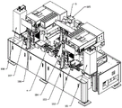
As shown in fig. 1, a solar laser processing apparatus includes a feeding device 101 for feeding a sheet material, a feeding alignment device 102 for centrally aligning the sheet material, a feeding buffer device 103 for buffering the sheet material, a fragment detection device 104 for detecting fragments of the sheet material, a laser processing unit 105 for laser processing the sheet material, a blanking buffer device 106 for buffering the sheet material, a blanking alignment device 107 for centrally aligning the sheet material, and a blanking device 108 for blanking the sheet material, which are sequentially arranged in sequence, wherein the laser processing unit 105 includes a double turntable device 4 and a laser processing device 5, and the feeding device 101, the feeding alignment device 102, the feeding buffer device 103, the fragment detection device 104, the double turntable device 4, the blanking buffer device 106, the blanking alignment device 107, and the blanking device 108 are sequentially butted to form a pipeline for conveying the sheet material.
The feeding device 101, the feeding aligning device 102, the feeding caching device 103, the fragment detecting device 104, the laser processing unit 105, the blanking caching device 106, the blanking aligning device 107 and the blanking device 108 are all installed on a marble platform, and the marble platform is adopted, so that the marble platform has the advantages of stable bearing and corrosion resistance.
The laser processing apparatus 5 includes a laser generator, an optical path, and a laser head.
As shown in fig. 3, the two solar laser processing apparatuses are arranged back to back, so as to further improve the production efficiency.
The solar laser processing equipment is preferably laser scribing equipment and is used for scribing process of the solar substrate.
The direction of conveying the flaky materials by the assembly line is the front-back direction, and the direction perpendicular to the assembly line is the left-right direction.
As shown in fig. 4 to 10, the feeding device 101 and the discharging device 108 both adopt the feeding and discharging device 1 with the same structure, but are symmetrically arranged in front and back.
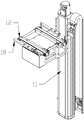
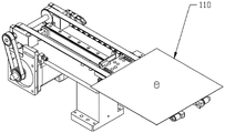
The loading and unloading device 1 comprises a material frame 15 for placing the sheet material 110, a material frame lifting mechanism 11, a material frame in-place conveying mechanism 12 and a material taking and placing mechanism 14, wherein the material frame 15 is arranged on the material frame in-place conveying mechanism 12, the material frame in-place conveying mechanism 12 is arranged on the material frame lifting mechanism 11, the material taking and placing mechanism 14 comprises a material taking and placing support 141, a material taking and placing motor 142, a material taking and placing telescopic cylinder 144 and a material taking and placing telescopic assembly line 145, the material taking and placing motor 142, the material taking and placing telescopic cylinder 144 and the material taking and placing telescopic assembly line 145 are respectively arranged on the material taking and placing bracket 141, the material taking and placing motor 141 is connected with the material taking and placing telescopic production line 145, drives a belt 1455 of the material taking and placing telescopic production line 145 to convey, the material taking and placing telescopic cylinder 144 is connected with the material taking and placing telescopic assembly line 145 and drives a belt 1455 of the material taking and placing telescopic assembly line 145 to stretch.
The taking and discharging telescopic production line 145 comprises a driving wheel 1451, a first driving wheel 1452, a second driving wheel 1453, a third driving wheel 1454 and a belt 1455, the belt 1455 is tensioned on the driving wheel 1451, the first driving wheel 1452, the second driving wheel 1453 and the third driving wheel 1454, the taking and discharging motor 142 is connected with the driving wheel 1451 through a belt transmission mechanism 143, the first driving wheel 1452 is fixedly installed on the taking and discharging bracket, and the second driving wheel 1453 and the third driving wheel 1454 are respectively and fixedly connected with the taking and discharging telescopic cylinder 144.
The material taking and placing telescopic cylinder 144 is connected with a material taking and placing telescopic slider 147, the material taking and placing telescopic slider 147 is in sliding fit with the material taking and placing bracket 141, and the second transmission wheel 1453 and the third transmission wheel 1454 are fixedly installed on the material taking and placing telescopic slider 147 respectively.
The first transmission wheel 1452, the second transmission wheel 1453 and the third transmission wheel 1454 are sequentially arranged from bottom to top.
The material taking and placing telescopic slide block 147 is provided with a position sensor 148 for detecting whether the material exists or is damaged.
The material taking and placing telescopic slider 147 is connected with the material taking and placing support 141 through a wire rail 146, so that the material taking and placing telescopic slider 147 slides and translates left and right on the material taking and placing support 141.
The material frame lifting mechanism 11 is connected with a lifting plate 19, the top of the lifting plate 19 is connected with a material frame pressing device 13, and convex teeth for placing sheet materials are arranged on the material frame 15 and can be used for placing a plurality of sheet materials at the same time.
The material frame pressing device 13 is driven by an air cylinder to realize material frame pressing.
Two sides of the material frame in-place conveying mechanism 12 are respectively provided with a material frame adjustable retaining edge 18.
The frame-in-place conveying mechanism 12 is preferably a belt conveying mechanism.
The front end of the material frame in-place conveying mechanism 12 is respectively provided with a material frame limiting mechanism 17 for limiting the advance of the material frame 15 and a position sensor 16 for detecting whether the material frame 15 advances in place.
The invention provides a loading and unloading device 1 for sheet materials, which has the following working principle:
when feeding, firstly, a material frame 15 filled with sheet materials is placed on the material frame in-place conveying mechanism 12, the material frame in-place conveying mechanism 12 conveys the material frame 15 forwards until the position sensor 16 feeds back the material frame 15 to be in place, when the material frame is in place, the material frame limiting mechanism 17 is pressed against the material frame 15, when the material frame 15 is in place, the material frame in-place conveying mechanism 12 stops conveying, the material frame pressing device 13 presses the material frame 15 downwards, the material frame lifting mechanism 11 descends to be in place, the material taking and placing telescopic cylinder 144 drives the third driving wheel 1454 to extend out, the belt 1455 obtains one sheet of sheet materials 110 and conveys the sheet materials forwards, and therefore automatic feeding of the sheet materials is achieved;
during blanking, the material taking and placing telescopic cylinder 144 drives the third driving wheel 1454 to extend, the belt 1455 conveys the sheet materials to the material frame 15, the material taking and placing telescopic cylinder 144 contracts, and the material frame lifting mechanism 11 ascends, so that the automatic blanking of the sheet materials is realized;
when the material frame 15 needs to be replaced, the material taking and placing telescopic cylinder 144 is contracted (to avoid interference with the material frame 15), and then the material frame 15 is taken down again, and a new material frame 15 is replaced.
As shown in fig. 11 to 14, the feeding alignment device 102 and the discharging alignment device 107 are both the alignment device 2 having the same structure, but are arranged symmetrically in front and rear.
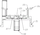
Aligning device 2 is including counterpointing mounting base 21, counterpoint driving motor 22 and counterpoint clamping mechanism, counterpoint clamping mechanism installs counterpoint mounting base 21 is last, counterpoint clamping mechanism includes two bilateral symmetry's clamping arm mechanism, clamping arm mechanism includes connecting rod 24 and clamping arm 25, counterpoint driving motor 22 is installed counterpoint mounting base 21 is last, counterpoint driving motor 22's rotation axis is connected with the swing portion, connecting rod 24's one end with the swing portion is articulated, connecting rod 24's the other end with clamping arm 25 is articulated, be equipped with the gyro wheel 26 that presss from both sides tight slice material on the clamping arm 25, clamping arm 25 with counterpoint mounting base 21 is sliding fit.
The swing part is a swing arm 23, one end of the swing arm 23 is hinged to one of the connecting rods 24, the other end of the swing arm 23 is hinged to the other connecting rod 24, the swing arm 23 is parallel to the horizontal plane, and the rotating shaft of the alignment driving motor 22 is perpendicular to the horizontal plane.
The contraposition mounting base 21 is provided with a clamping in-position sensor 28 for detecting whether clamping is in place.
One end of the swing arm 23 is connected with a clamping-in-place sensor triggering baffle 211 for triggering the clamping-in-place sensor 28.
The alignment mounting base 21 is provided with a clamping in-place sensor mounting groove 212, and the clamping in-place sensor 28 is mounted on the clamping in-place sensor mounting groove 212.
The clamping arm 25 is connected to the aligning mounting base 21 by a rail slider mechanism 27.
The gripping arm 25 is provided with at least three rollers 26, which rollers 26 are arranged in a straight line and parallel to the conveying direction of the conveyor belt conveying the sheet material.
The aligning device further comprises two front and back symmetrical edge searching sensing units, each edge searching sensing unit comprises an edge searching sensor 210 for detecting the edge of the sheet material and an edge searching sensor mounting plate 29, each edge searching sensor mounting plate 29 is mounted on the aligning mounting base 21, and each edge searching sensor 210 is mounted on the edge searching sensor mounting plate 29.
Two edge-searching sensing units which are symmetrical front and back are arranged on the front side and the back side of one of the clamping arms 25, the front and back direction is the conveying direction of a conveying belt for conveying the flaky materials, the left and right direction is perpendicular to the conveying direction of the conveying belt for conveying the flaky materials, and the two clamping arm mechanisms are symmetrically arranged left and right along the central axis of the conveying belt for conveying the flaky materials.
Whether the accessible is sought limit sensor 210 and is detected the slice material and counterpoint untiely, or has the off normal, has the hypotenuse, when two are sought limit sensor 210 and all detect the slice material, then the edge that explains the slice material is neat counterpoint, when only one is sought limit sensor 210 and all detects the slice material, then the off normal has taken place in the position of explaining the slice material, has the hypotenuse, counterpoints untiely, then reports to the police this moment and suggests.
According to the alignment device 2 for sheet materials, the swing arm 23 is driven to swing through the alignment driving motor 22, the clamping arm 25 is driven to move in a centering and translation mode along the guide rail sliding block mechanism 27 through the connecting rod 24, so that the sheet materials on the conveying belt are clamped in a centering mode, the sheet materials are aligned in the center, and the position consistency of the sheet materials is improved.
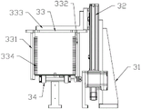
As shown in fig. 15 to 18, the feeding buffer device 103 and the discharging buffer device 106 both adopt the buffer devices 3 with the same structure, but are symmetrically arranged in front and back.
The buffer material frame 33 comprises a buffer material frame top plate 333, a buffer material frame first side plate 331 and a buffer material frame second side plate 332, the buffer material frame top plate 333 is fixedly connected with the buffer Z-axis lifting module 32, the top of the buffer material frame first side plate 331 and the top of the buffer material frame second side plate 332 are respectively fixedly connected with the buffer material frame top plate 333, the buffer material frame first side plate 331 and the buffer material frame second side plate 332 are parallel, the buffer material frame first side plate 331 and the buffer material frame second side plate 332 are provided with a convex tooth 334 for placing sheet-shaped materials, and the buffer section transmission line 34 is located between the buffer material frame first side plate 331 and the buffer material frame second side plate 332.
The top of the first side plate 331 of the buffer material frame and the top of the second side plate 332 of the buffer material frame are respectively and fixedly connected with the top plate 333 of the buffer material frame through a spacing adjustment structure.
The distance adjusting structure comprises an adjustable round hole 335 and an adjustable bolt which are located on the top plate 333 of the buffer material frame, and the distance between the first side plate 331 of the buffer material frame and the second side plate 332 of the buffer material frame can be adjusted through the distance adjusting structure, so that the device is suitable for sheet materials 35 of different specifications, and the universality of the device is improved.
The interval adjusting structure further comprises a graduated scale 336 located on the top plate 333 of the buffer material frame, and provides a reference for adjusting the interval between the first side plate 331 of the buffer material frame and the second side plate 332 of the buffer material frame, so that the operation is convenient.
The cache segment transfer line 34 includes a cache segment conveyor motor 341 and a cache segment conveyor 342, the cache segment conveyor motor 341 being mounted on the cache mounting rack 31, the cache segment conveyor motor 341 being connected to the cache segment conveyor 342. The buffer section conveyor belt 342 is located between the buffer material frame first side plate 331 and the buffer material frame second side plate 332.
The buffer segment conveying line 34 is used for conveying the sheet materials and is butted in a production line.
The buffer Z-axis mounting rack 311 and the buffer motor mounting rack 312 are both L-shaped brackets.
The buffer section conveyor belt 342 is parallel to the horizontal plane, and the buffer section conveyor belt motor 341 is located in front of the buffer frame first side plate 331 and the buffer frame second side plate 332, so as to avoid interference between the buffer frame 33 and the buffer section conveyor belt motor 341.
The width of the buffer section conveyor belt 342 is smaller than the minimum distance between the convex teeth of the first side plate 331 of the buffer material frame and the convex teeth of the second side plate 332 of the buffer material frame, so that the buffer section conveyor belt 342 can be prevented from interfering with the buffer material frame 33.
The first side plate 331 and the second side plate 332 of the buffer material frame are both perpendicular to the horizontal plane, and the top plate 333 of the buffer material frame is L-shaped.
The invention provides a caching device for flaky materials, which has the following working principle:
when the front materials are stacked and the flaky materials need to be cached, the caching material frame 33 is driven to ascend through the caching Z-axis lifting module 32, so that the flaky materials are cached on the caching material frame 33;
when the front materials are insufficient and the cached flaky materials need to be released, the cache Z-axis lifting module 32 drives the cache material frame 33 to descend, so that the flaky materials are released on the cache segment conveying line 34;
similarly, when the material frame of material loading needs to be changed, the sheet material of buffer memory is released, and when the material frame of unloading needs to be changed, the sheet material of buffer memory is released.
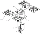
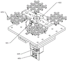
As shown in fig. 19 to 22, the dual reel device 4 includes a first reel device 41 and a second reel device 42.
The first rotating disc device 41 comprises a first rotating disc motor 411, a first jig mounting plate 412 and four first vacuum chucks 413, a rotating shaft of the first rotating disc motor 411 is connected with the first jig mounting plate 412, two of the first vacuum chucks 413 are fixed at one end of the first jig mounting plate 412, the other two first vacuum chucks 413 are fixed at the other end of the first jig mounting plate 412, the first vacuum chucks 413 are located above the sheet materials to be adsorbed, and the first vacuum chucks 413 adsorb the sheet materials to be adsorbed from the top.
The first turntable motor 411 and the second turntable motor 421 are both DD motors.
The rotation locus circle of the first vacuum chuck 413 intersects with the rotation locus circle of the second vacuum chuck 423, and the intersection of the two is the position of the first vacuum chuck 413 and the second vacuum chuck 423 for connecting the sheet materials.
The double-turntable device further comprises two CCD image capturing modules 43 for positioning, the two CCD image capturing modules 43 are hung at the position of the sheet material which is connected with the first vacuum sucker 413 and the second vacuum sucker 423, and the CCD image capturing modules 43 can be used for capturing images of the material so as to drive and guide laser processing.
The CCD image capturing module 43 is a dual-CCD diagonal image capturing module, and the detection accuracy can be improved by using the dual-CCD diagonal image capturing module; the diagonal mode is preferably adopted in this embodiment, and a single CCD mode may also be adopted.
Every two first vacuum chucks 413 are connected through a first vacuum chuck beam 414, the first vacuum chuck beam 414 is vertically installed at the end part of the first jig mounting plate 412, and the second jig mounting plate 422 is in an I shape.
The first turntable motor 411 drives the first jig mounting plate 412 at a rotation angle of 180 degrees, and the second turntable motor 421 drives the second jig mounting plate 422 at a rotation angle of 180 degrees.
The first vacuum chuck 413 and the second vacuum chuck 423 are not lifted along the Z axis, the first vacuum chuck 413 and the second vacuum chuck 423 are both connected with pressure detection meters 416 and 426 for detecting vacuum values, and the first vacuum chuck 413 and the second vacuum chuck 423 are both connected with air guide slip rings 415 and 425.
The double-turntable device further comprises a workbench 427, the second turntable motor 421 is mounted on the workbench 427, a zigzag support 428 is mounted on the workbench 427, a rotation in-place sensor 429 for detecting whether the second jig mounting plate 422 rotates in place is mounted on the zigzag support 428, and a trigger baffle 424 for triggering the rotation in-place sensor 429 is connected to a side surface of the second jig mounting plate 422.
The invention relates to a double-turntable device for flaky materials, which has the following working principle:
dividing the station into a conveyor belt station, a CCD image capturing station and a laser processing station;
the first rotating disk device 41 conveys: the four first vacuum chucks 413 adsorb materials, wherein the two first vacuum chucks 413 positioned at the outer side adsorb raw materials (i.e. materials which are not processed yet) at the conveyor belt station, the two first vacuum chucks 413 positioned at the inner side adsorb clinker (i.e. materials which are processed completely) on the CCD image capturing station, the four first vacuum chucks 413 are driven by the first rotary table motor 411 to rotate 180 degrees, so that the clinker is placed back to the conveyor belt station and conveyed to the next station, the raw materials are conveyed to the CCD image capturing station for CCD image capturing, and then the second rotary table device 41 is used for conveying the materials;
the second carousel means 41 conveys: after the CCD image capture is completed, the four second vacuum suction cups 423 absorb the materials, wherein the two second vacuum suction cups 423 located at the outer side absorb the raw materials that have completed the CCD image capture, the two second vacuum suction cups 423 located at the inner side absorb the processed raw materials, the second turntable motor 421 drives the four second vacuum suction cups 423 to rotate 180 degrees, so as to place the raw materials at the CCD image capture station, and when the first vacuum suction cup 413 is taken back, the raw materials are placed at the laser processing station, and when the laser processing is performed, the first turntable device 41 is performed to convey the materials;
the materials are conveyed to and fro through the first rotating disc device 41 and the second rotating disc device 42, so that the conveying speed of the materials is greatly improved.
As shown in fig. 2, the present invention further provides a solar laser processing method, which is based on the solar laser processing apparatus to perform the following processes:
s1, feeding the raw materials to a production line through a feeding device, wherein the raw materials are materials which do not finish laser processing, and the clinker materials are materials which finish laser processing;
s2, conveying the raw materials to a material feeding alignment device by a production line, and finishing the centering alignment of the raw materials by the material feeding alignment device;
s3, the feeding buffer device performs the following substeps:
s301, if the materials in front of the production line are stacked, the loading cache device caches the raw materials;
s302, if the materials in front of the production line are lack, releasing the buffered raw materials by the feeding buffer device;
s303, if the materials in front of the production line are not accumulated or lacked, the feeding caching device does not act;
s4, conveying the raw material to a fragment detection device by the production line, and carrying out fragment detection on the raw material by the fragment detection device;
s5, the laser processing unit carries out the following substeps:
if the broken pieces exist, taking away;
s501, the four first vacuum chucks adsorb materials, wherein the two first vacuum chucks on the outer side adsorb raw materials on a conveyor belt station, the two first vacuum chucks on the inner side adsorb clinker on a CCD image capturing station, a first turntable motor drives the four first vacuum chucks to rotate 180 degrees, the clinker is placed back to the conveyor belt station and is conveyed to the next station, the raw materials are conveyed to the CCD image capturing station, and CCD image capturing is carried out through a CCD image capturing module;
s502, after the CCD image capture is finished, the four second vacuum chucks adsorb materials, wherein the two second vacuum chucks on the outer side adsorb raw materials which have finished the CCD image capture, the two second vacuum chucks on the inner side adsorb clinker which has finished the laser processing, and a second turntable motor drives the four second vacuum chucks to rotate 180 degrees, so that the clinker is placed on the CCD image capture station, and after the first vacuum chuck takes back, the raw materials are placed on the laser processing station for laser processing;
s6, the blanking buffer device performs the following substeps:
s301, if the materials in front of the production line are stacked, the blanking cache device caches the raw materials;
s302, if the materials in front of the production line are lack, the blanking cache device releases the cached raw materials;
s303, if the materials in front of the production line are not accumulated or lacked, the blanking caching device does not act;
s7, conveying the clinker to a discharging alignment device by the production line, and performing centering alignment on the clinker by the discharging alignment device;
and S8, conveying the clinker to a blanking device by the production line, and blanking the clinker by the blanking device.
The solar laser processing equipment and the method provided by the invention have the following advantages:
1. the laser scribing is adopted, so that the system is stable, the operation and the maintenance are convenient, and the system is ensured to have good dynamic quality;
2. the processing speed of the equipment is very high, the productivity is high,
UPH (capacity) is more than or equal to 5400 to 6000PCS (single side);
3. good performance
The utilization rate is more than or equal to 98 percent
Mean Time To failure (MTTR) repair Time ≦ 2 hours
Mean Time Between Failures (MTBF) of 200 hours or more
4. The double DD rotary platform has the advantages of high precision, high speed and stability;
5. by adopting the CCD system, the positioning can be accurately realized, and the clamping requirement is reduced;
6. the laser head is adopted for scribing, the speed is high, and the cutting effect is good;
7. by adopting fragment detection, intelligent feedback can be realized, and material removal at the front end can be realized;
8. each device adopts the modularized design, and the function is easy to expand.
The solar laser processing equipment and the method provided by the invention can be used for laser processing of solar substrates, such as scribing, cutting and the like, and can also be used for laser processing of other sheet materials.
The foregoing is a more detailed description of the invention in connection with specific preferred embodiments and it is not intended that the invention be limited to these specific details. For those skilled in the art to which the invention pertains, several simple deductions or substitutions can be made without departing from the spirit of the invention, and all shall be considered as belonging to the protection scope of the invention.
Claims (10)
1. The utility model provides a solar energy laser beam machining equipment which characterized in that: the sheet material feeding device, the sheet material feeding aligning device, the sheet material feeding caching device, the sheet material fragment detection device, the laser processing unit, the sheet material discharging caching device, the sheet material discharging aligning device and the sheet material discharging device are sequentially arranged according to the processing sequence, the laser processing unit is used for carrying out laser processing on the sheet material, the sheet material discharging caching device is used for caching the sheet material, the sheet material discharging aligning device is used for carrying out centered alignment on the sheet material, and the sheet material discharging device is used for discharging the sheet material.
2. The solar laser processing apparatus according to claim 1, characterized in that: the direction of conveying the flaky materials by the assembly line is taken as the front-back direction, two feeding and discharging devices which are symmetrically arranged front and back respectively form a feeding device and a discharging device, the feeding and discharging device comprises a material frame for placing the flaky materials, a material frame lifting mechanism, a material frame in-place conveying mechanism and a material taking and discharging mechanism, wherein the material frame is arranged on the material frame in-place conveying mechanism, the material frame in-place conveying mechanism is arranged on the material frame lifting mechanism, the material taking and discharging mechanism comprises a material taking and discharging support, a material taking and discharging motor, a material taking and discharging telescopic cylinder and a material taking and discharging telescopic assembly line, the material taking and discharging motor, the material taking and discharging telescopic assembly line and the material taking and discharging telescopic assembly line are respectively arranged on the material taking and discharging support, the material taking and discharging motor is connected with the material taking and discharging telescopic assembly line to drive the belt conveying of the material taking and discharging assembly line, and the material taking and discharging telescopic cylinder is connected with the material taking and discharging telescopic assembly line, and driving the belt of the material taking and placing telescopic assembly line to stretch.
3. The solar laser processing apparatus according to claim 2, characterized in that: get flexible assembly line of material of putting includes drive wheel, first drive wheel, secondary drive wheel, third drive wheel and belt, the belt tensioning is in on drive wheel, first drive wheel, secondary drive wheel and the third drive wheel, get the material motor with the drive wheel is connected, first drive wheel fixed mounting be in get on the blowing support, secondary drive wheel and third drive wheel respectively with get material telescopic cylinder fixed connection, it is connected with gets the flexible slider of material to get the flexible cylinder of blowing, get the flexible slider of blowing with it is sliding fit to get the material support, secondary drive wheel and third drive wheel respectively fixed mounting be in get on the flexible slider of material, first drive wheel, secondary drive wheel and third drive wheel are arranged from bottom to top in proper order.
4. The solar laser processing apparatus according to claim 1, characterized in that: the direction of using the assembly line to carry the slice material is the fore-and-aft direction, and then the aligning device of two front and back symmetrical arrangement has constituted material loading aligning device and unloading aligning device respectively, aligning device includes counterpoint mounting base, counterpoint actuating motor and counterpoint clamping mechanism, counterpoint clamping mechanism installs on the counterpoint mounting base, counterpoint clamping mechanism includes the tight arm mechanism of two bilateral symmetry's clamp, clamp arm mechanism includes connecting rod and clamp arm, counterpoint actuating motor installs on the counterpoint mounting base, counterpoint actuating motor's rotation axis is connected with swing portion, the one end of connecting rod with swing portion is articulated, the other end of connecting rod with it is articulated to press from both sides tight arm, be equipped with the gyro wheel that presss from both sides tight slice material on the tight arm, press from both sides tight arm with counterpoint mounting base is sliding fit.
5. The solar laser processing apparatus according to claim 4, wherein: the swing portion is a swing arm, one end of the swing arm is hinged to one of the connecting rods, the other end of the swing arm is hinged to the other connecting rod, the swing arm is parallel to the horizontal plane, a rotating shaft of the alignment driving motor is perpendicular to the horizontal plane, a clamping in-place sensor which detects whether clamping is in place or not is installed on the alignment installation base, one end of the swing arm is connected with a clamping in-place sensor trigger baffle which triggers the clamping in-place sensor, the alignment device further comprises two front and back symmetrical edge searching sensing units, each edge searching sensing unit comprises an edge searching sensor and an edge searching sensor installation plate which detect the edge of a sheet material, the edge searching sensor installation plates are installed on the alignment installation base, the edge searching sensors are installed on the edge searching sensor installation plates, the two front and back symmetrical edge searching sensing units are arranged on the front side and the back side of one of the clamping arms, the two clamping arm mechanisms are arranged in bilateral symmetry along the central axis of the conveyor belt for conveying the flaky materials.
6. The solar laser processing apparatus according to claim 1, characterized in that: the direction of conveying the flaky materials by the assembly line is taken as the front-back direction, two buffer devices symmetrically arranged front and back respectively form a feeding buffer device and a discharging buffer device, the buffer device comprises a buffer mounting frame, a buffer Z-axis lifting module, a buffer material frame and a buffer section transmission line, the buffer Z-axis lifting module and the buffer section transmission line are respectively mounted on the buffer mounting frame, the buffer material frame is mounted on the buffer Z-axis lifting module, the buffer material frame comprises a buffer material frame top plate, a buffer material frame first side plate and a buffer material frame second side plate, the buffer material frame top plate is fixedly connected with the buffer Z-axis lifting module, the top of the buffer material frame first side plate and the top of the buffer material frame second side plate are respectively fixedly connected with the buffer material frame top plate, and the buffer material frame first side plate and the buffer material frame second side plate are parallel, the first side plate of the cache material frame and the second side plate of the cache material frame are both provided with convex teeth for placing flaky materials, and the cache section transmission line is located between the first side plate of the cache material frame and the second side plate of the cache material frame.
7. The solar laser processing apparatus according to claim 1, characterized in that: the solar laser processing equipment is provided with two solar laser processing equipment which are arranged back to back.
8. The solar laser processing apparatus according to claim 1, characterized in that: the double-turntable device comprises a first turntable device and a second turntable device, the first turntable device comprises a first turntable motor, a first jig mounting plate and four first vacuum suckers, a rotating shaft of the first turntable motor is connected with the first jig mounting plate, two of the first vacuum suckers are fixed at one end of the first jig mounting plate, the other two of the first vacuum suckers are fixed at the other end of the first jig mounting plate, the first vacuum suckers are positioned above the flaky materials to be adsorbed, the first vacuum suckers adsorb the flaky materials to be adsorbed from the upper part, the second turntable device comprises a second turntable motor, a second jig mounting plate and four second vacuum suckers, the rotating shaft of the second turntable motor is connected with the second jig mounting plate, two of the second vacuum suckers are fixed at one end of the second jig mounting plate, and the other two second vacuum suction cups are fixed at the other end of the second jig mounting plate, the second vacuum suction cups are positioned below the sheet materials to be adsorbed, and the second vacuum suction cups adsorb the sheet materials to be adsorbed from the lower part.
9. The solar laser processing apparatus according to claim 8, wherein: the rotary track circle of the first vacuum chuck is intersected with the rotary track circle of the second vacuum chuck, the intersection of the first vacuum chuck and the second vacuum chuck is the position of the sheet material for connection of the first vacuum chuck and the second vacuum chuck, the double-rotary-disc device further comprises two CCD image capturing modules, the two CCD image capturing modules are hung at the position of the sheet material for connection of the first vacuum chuck and the second vacuum chuck, the position of the sheet material for connection of the first vacuum chuck and the second vacuum chuck is an image capturing CCD station, the intersection of the rotary track circle of the first vacuum chuck and the assembly line is the position for taking and placing the material, the position is an assembly line station, and the position of the laser processing device is a laser processing station.
10. A solar laser processing method is characterized in that: the following process is performed based on the solar laser processing apparatus according to claim 9:
s1, feeding the raw materials to a production line through a feeding device, wherein the raw materials are materials which do not finish laser processing, and the clinker is materials which finish laser processing;
s2, conveying the raw materials to a material feeding alignment device by a production line, and finishing the centering alignment of the raw materials by the material feeding alignment device;
s3, the feeding buffer device performs the following substeps:
if the materials in front of the production line are stacked, the loading cache device caches the raw materials;
if the materials in front of the production line are lacked, the feeding buffer device releases the buffered raw materials;
if the materials in front of the production line are not accumulated or lacked, the feeding cache device does not act;
s4, conveying the raw material to a fragment detection device by the production line, and carrying out fragment detection on the raw material by the fragment detection device;
s5, the laser processing unit carries out the following substeps:
the four first vacuum chucks adsorb materials, wherein the two first vacuum chucks on the outer side adsorb raw materials on a conveyor belt station, the two first vacuum chucks on the inner side adsorb clinker on a CCD image capturing station, a first turntable motor drives the four first vacuum chucks to rotate 180 degrees, the clinker is placed back to the conveyor belt station and is conveyed to the next station, the raw materials are conveyed to the CCD image capturing station, and CCD image capturing is carried out through a CCD image capturing module;
after the CCD image capture is finished, the four second vacuum chucks adsorb materials, wherein the two second vacuum chucks on the outer side adsorb raw materials which have finished the CCD image capture, the two second vacuum chucks on the inner side adsorb clinker which has finished the laser processing, and the four second vacuum chucks are driven by a second turntable motor to rotate 180 degrees, so that the clinker is placed on the CCD image capture station, and after the first vacuum chuck takes back, the raw materials are placed on the laser processing station for laser processing;
s6, the blanking caching device performs the following substeps:
if the materials in front of the production line are stacked, the blanking caching device caches the raw materials;
if the materials in front of the production line are lacked, the blanking cache device releases the cached raw materials;
if the materials in front of the production line are not accumulated or lacked, the blanking cache device does not act;
s7, conveying the clinker to a discharging alignment device by the production line, and performing centering alignment on the clinker by the discharging alignment device;
and S8, conveying the clinker to a blanking device by the production line, and blanking the clinker by the blanking device.
Priority Applications (1)
| Application Number | Priority Date | Filing Date | Title |
|---|---|---|---|
| CN202210924961.6A CN114985943B (en) | 2022-08-03 | 2022-08-03 | Laser processing equipment and method for solar substrate |
Applications Claiming Priority (1)
| Application Number | Priority Date | Filing Date | Title |
|---|---|---|---|
| CN202210924961.6A CN114985943B (en) | 2022-08-03 | 2022-08-03 | Laser processing equipment and method for solar substrate |
Publications (2)
| Publication Number | Publication Date |
|---|---|
| CN114985943A true CN114985943A (en) | 2022-09-02 |
| CN114985943B CN114985943B (en) | 2022-11-08 |
Family
ID=83021153
Family Applications (1)
| Application Number | Title | Priority Date | Filing Date |
|---|---|---|---|
| CN202210924961.6A Active CN114985943B (en) | 2022-08-03 | 2022-08-03 | Laser processing equipment and method for solar substrate |
Country Status (1)
| Country | Link |
|---|---|
| CN (1) | CN114985943B (en) |
Cited By (1)
| Publication number | Priority date | Publication date | Assignee | Title |
|---|---|---|---|---|
| CN116371751A (en) * | 2023-04-27 | 2023-07-04 | 苏州天准科技股份有限公司 | Energy level expansion blanking separation equipment and method |
Citations (7)
| Publication number | Priority date | Publication date | Assignee | Title |
|---|---|---|---|---|
| CN107344676A (en) * | 2017-07-24 | 2017-11-14 | 深圳市嘉熠精密自动化科技有限公司 | A kind of automatic loading and unloading mechanism |
| CN207743211U (en) * | 2017-12-05 | 2018-08-17 | 武汉帝尔激光科技股份有限公司 | A kind of solar battery sheet laser scribing device |
| CN209632297U (en) * | 2019-01-23 | 2019-11-15 | 武汉帝尔激光科技股份有限公司 | A kind of big production capacity laser process equipment |
| CN211768864U (en) * | 2020-03-18 | 2020-10-27 | 南京中江新材料科技有限公司 | Novel copper sheet of DBC ceramic substrate and equipment of potsherd automatic feeding to fritting furnace |
| CN214721415U (en) * | 2021-03-01 | 2021-11-16 | 江阴德龙能源设备有限公司 | Solar cell laser scribing machine with splitting position compensation |
| CN216177538U (en) * | 2021-09-02 | 2022-04-05 | 武汉帝尔激光科技股份有限公司 | Laser processing apparatus |
| CN114799546A (en) * | 2022-04-01 | 2022-07-29 | 武汉华工激光工程有限责任公司 | Full-automatic laser drilling method and equipment |
-
2022
- 2022-08-03 CN CN202210924961.6A patent/CN114985943B/en active Active
Patent Citations (7)
| Publication number | Priority date | Publication date | Assignee | Title |
|---|---|---|---|---|
| CN107344676A (en) * | 2017-07-24 | 2017-11-14 | 深圳市嘉熠精密自动化科技有限公司 | A kind of automatic loading and unloading mechanism |
| CN207743211U (en) * | 2017-12-05 | 2018-08-17 | 武汉帝尔激光科技股份有限公司 | A kind of solar battery sheet laser scribing device |
| CN209632297U (en) * | 2019-01-23 | 2019-11-15 | 武汉帝尔激光科技股份有限公司 | A kind of big production capacity laser process equipment |
| CN211768864U (en) * | 2020-03-18 | 2020-10-27 | 南京中江新材料科技有限公司 | Novel copper sheet of DBC ceramic substrate and equipment of potsherd automatic feeding to fritting furnace |
| CN214721415U (en) * | 2021-03-01 | 2021-11-16 | 江阴德龙能源设备有限公司 | Solar cell laser scribing machine with splitting position compensation |
| CN216177538U (en) * | 2021-09-02 | 2022-04-05 | 武汉帝尔激光科技股份有限公司 | Laser processing apparatus |
| CN114799546A (en) * | 2022-04-01 | 2022-07-29 | 武汉华工激光工程有限责任公司 | Full-automatic laser drilling method and equipment |
Cited By (1)
| Publication number | Priority date | Publication date | Assignee | Title |
|---|---|---|---|---|
| CN116371751A (en) * | 2023-04-27 | 2023-07-04 | 苏州天准科技股份有限公司 | Energy level expansion blanking separation equipment and method |
Also Published As
| Publication number | Publication date |
|---|---|
| CN114985943B (en) | 2022-11-08 |
Similar Documents
| Publication | Publication Date | Title |
|---|---|---|
| CN107097993B (en) | Full-automatic film sticking machine | |
| CN107999404B (en) | Metal plug stacker | |
| CN106515201A (en) | High-precision fully-automatic screen printing machine capable of printing double pieces in one process | |
| CN111940306A (en) | Detection device and detection method for semiconductor chip | |
| CN114141905B (en) | A fold tile production line for producing solar cell cluster | |
| CN107986026A (en) | A kind of full-automatic mechanical hand equipment | |
| CN210309464U (en) | Automatic laminating equipment for liquid crystal display | |
| CN114985943B (en) | Laser processing equipment and method for solar substrate | |
| CN115647598A (en) | Automatic marking working method of battery cover plate | |
| CN112986013A (en) | Building material glass surface stress detection system and detection process thereof | |
| CN210590943U (en) | Soft-to-hard laminating feeding and discharging structure suitable for touch screen | |
| CN116331834A (en) | Automatic go up and down feed liquid bag lamp and examine machine | |
| CN111137679A (en) | Automatic pad pasting and two-dimensional code equipment | |
| CN113998429A (en) | Automatic feeding equipment of PCB (printed circuit board) drilling machine | |
| CN218841009U (en) | Efficiency detection device for double-half battery piece | |
| CN217190994U (en) | Film-pasted glass sheet detection marking equipment | |
| CN111217142A (en) | Rotary disc device | |
| CN113333515B (en) | Plate bending processing method | |
| CN211594204U (en) | Automatic cleaning system | |
| CN113526114A (en) | Full-automatic feeding and visual detection device | |
| CN113437003A (en) | High-speed sheet arranging machine | |
| CN218282710U (en) | Double-side photographing detection device with automatic feeding structure | |
| CN217913514U (en) | Double-turntable device for flaky materials and solar laser processing equipment | |
| CN114192613B (en) | Feeding and discharging device of bending machine | |
| CN218230921U (en) | Automatic unloader that goes up of chip tray |
Legal Events
| Date | Code | Title | Description |
|---|---|---|---|
| PB01 | Publication | ||
| PB01 | Publication | ||
| SE01 | Entry into force of request for substantive examination | ||
| SE01 | Entry into force of request for substantive examination | ||
| GR01 | Patent grant | ||
| GR01 | Patent grant |