Disclosure of Invention
The invention provides an integrated device for cutting and polishing a steel bar for a building engineering and a using method thereof, aiming at overcoming the defects of the prior art and solving the problems that the position of the steel bar needs to be repeatedly adjusted due to the fact that the number of the steel bars cut each time is large during cutting, and the cutting efficiency of the steel bar is low due to the fact that the processes of marking the steel bar, fixing the steel bar and cutting the steel bar are complicated manually.
The technical scheme adopted by the invention for solving the technical problems is as follows: the invention relates to a cutting and polishing integrated device for reinforcing steel bars for building engineering and a using method thereof, comprising a device shell, wherein a glass door is arranged on the outer wall of the device shell in a sliding manner, a first supporting plate is fixedly arranged on the inner wall of the device shell, a power device is arranged on the side wall of the device shell, a feed inlet is formed in one side of the device shell, reinforcing steel bars are arranged on the inner wall of the feed inlet in a sliding manner, a clamp is arranged on the outer wall of each reinforcing steel bar in a sliding manner, a first switch and a second switch are fixedly arranged on the other side of the device shell, a polishing device is arranged at the top end of one side of the device shell, a power mechanism is arranged on the inner wall of the power device, a saw blade is arranged above each reinforcing steel bar, a protective shell is fixedly arranged on the outer wall of each saw blade, a first motor is fixedly arranged on the side wall of each protective shell, and a second connecting rod is fixedly arranged on the side wall of each protective shell, first square groove has been seted up to the below of reinforcing bar, first square groove is seted up at the inner wall of first backup pad, has improved the work efficiency of device.
Preferably, power unit is including installing the first supporting block at the power device inner wall, the top fixed mounting of first supporting block has the second motor, the lateral wall fixed mounting of second motor has first half tooth gear, first slide mechanism is installed to the lateral wall of first half tooth gear, slewing mechanism is installed to the opposite side of first half tooth gear, provides automatic function for the device.
Preferably, first slide mechanism is including installing the second semi-tooth gear at first semi-tooth gear lateral wall, integral type rack plate is installed to the lateral wall of second semi-tooth gear, mesh between second semi-tooth gear and the integral type rack plate, the upper and lower both sides of integral type rack plate all fixed mounting have the head rod, one of them the head rod is L shape, the one end fixed mounting of head rod has the second supporting shoe, the one end fixed mounting of second supporting shoe has the second connecting rod, realizes automatic cutting.
Preferably, slewing mechanism is including installing the first gear at first half tooth gear lateral wall, meshing between first half tooth gear and the first gear, the inner wall fixed mounting of first gear has first round bar, the one end fixed mounting of first round bar has first conical gear, second conical gear is installed to first conical gear's lateral wall, meshing between first conical gear and the second conical gear, second conical gear's lateral wall fixed mounting has the second round bar, first round bar's one end and the one end of second round bar are through first fixed plate fixed connection, second slide mechanism is installed to the one end of first round bar, pushing mechanism is installed to the one end of second round bar, realizes the automation of device.
Preferably, the pushing mechanism comprises a first connecting plate arranged at one end of a second round rod, a second connecting plate is arranged at one end of the first connecting plate, a third connecting rod is fixedly arranged on the side wall of the second connecting plate, pushing devices are arranged on two sides of the third connecting rod, the first connecting plate and the second connecting plate are connected through a bearing, a bearing seat is arranged on two sides of one end of the second connecting plate, the bearing seat is connected with the second connecting plate through a bearing, an elastic cushion is attached to the bottom of the bearing seat, a sliding device is arranged on the outer wall of the bearing seat, the bearing seat is connected with the sliding device through a bearing, the sliding device is convex, a round groove is formed in the inner wall of the sliding device, a reinforcing steel bar is arranged on the outer wall of the round groove, the reinforcing steel bar slides on the inner wall of the round groove, and the bottom end of the sliding device is embedded in the inner wall of a second square groove, the inner wall at first backup pad is seted up in the square groove of second, has improved production efficiency.
Preferably, the second sliding mechanism comprises a third bevel gear installed at one end of the first round bar, a fourth bevel gear is installed on the side wall of the third bevel gear, the third bevel gear is meshed with the fourth bevel gear, a third round bar is fixedly installed at the bottom end of the fourth bevel gear, one end of the first round bar is fixedly connected with one end of the third round bar through a second fixing plate, a fifth bevel gear is fixedly installed at one end of the third round bar, a sixth bevel gear is installed on the side wall of the fifth bevel gear, the fifth bevel gear is meshed with the sixth bevel gear, a fourth round bar is fixedly installed on the inner wall of the sixth bevel gear, one end of the third round bar is fixedly connected with one end of the fourth round bar through a third fixing plate, a third connecting plate is fixedly installed at one end of the fourth round bar, and a first rack plate is installed at one end of the third connecting plate, the third connecting plate is connected with the first rack plate through a bearing, the second gear is installed on the side wall of the first rack plate, the first rack plate is meshed with the second gear, the third supporting block is installed on the outer wall of the second gear, the second gear is connected with the third supporting block through a bearing, one side of the third supporting block is fixed on the side wall of the first supporting plate, and the clamping mechanism is fixedly installed on the side wall of the second gear, so that the automation of the device is realized.
Preferably, fixture is including installing the threaded rod at second gear lateral wall, four sliding blocks are installed to the outer wall of threaded rod, the top fixed mounting of sliding block has telescopic machanism, has improved the productivity.
Preferably, telescopic machanism is including installing the fourth connecting rod on the sliding block top, the outer wall slidable mounting of fourth connecting rod has the fifth connecting rod, the fourth connecting rod slides at the inner wall of fifth connecting rod, has improved work efficiency.
Preferably, the fixed screw is installed to the outer wall of fifth connecting rod, the fifth connecting rod passes through threaded connection, four with the fixed screw is all installed and through threaded connection to the outer wall of fifth connecting rod, has improved work efficiency.
Preferably, the integrated device for cutting and polishing the reinforcing steel bar for the building engineering and the using method thereof comprise the following steps:
s1, in the building, the steel bar is usually used in concrete, the earthquake resistance of the building can be enhanced, but the steel bar needs to be cut into the same length for use, a worker opens the glass door in the first step, the steel bar with qualified length is placed in the middle of the clamp, the distance is adjusted, the fourth connecting rod is pulled, the fourth connecting rod moves from the inner wall of the fifth connecting rod, the stop block can become one end of the steel bar, the other end of the steel bar reaches the position below the saw blade, the fixing screw is rotated, so that one end of the fixing screw extrudes the fourth connecting rod to fix the fourth connecting rod, and then the steel bar is placed in the inner wall of the feed port;
s2, in the second step, a first switch and a second switch are pressed to be switched on and switched off, so that a first motor and a second motor are started, the first motor drives a saw blade to rotate, the second motor drives a first half-toothed gear to rotate, the first half-toothed gear drives a second half-toothed gear to rotate, the second half-toothed gear drives an integrated rack plate to slide up and down on the inner wall of a second supporting block, the integrated rack plate drives a first connecting rod to move, the first connecting rod at one end drives a second connecting rod to move due to the fact that the first connecting rod is L-shaped, the first connecting rod drives the second connecting rod to move, the second connecting rod drives a protective shell to move back and forth, repeated cutting is achieved, meanwhile, the first half-toothed gear drives a first gear to rotate, the first round rod drives a first conical gear to rotate, the first round rod drives a second conical gear to rotate, the second conical gear drives a second round rod to rotate, and the second round rod drives the first connecting plate to rotate, the first connecting plate drives the second connecting plate to rotate, the second connecting plate rotates to incline the bearing seat, the bearing seat drives the sliding device to move, the bearing seat returns to the right and the reinforcing steel bar continues to move forward for a certain distance through an elastic cushion at the bottom of the bearing seat, so that the sliding device drives the reinforcing steel bar to move, the first round bar drives the third conical gear to rotate, the third conical gear drives the fourth conical gear to rotate, the fourth conical gear drives the third round bar to rotate, the third round bar drives the fifth conical gear to rotate, the fifth conical gear drives the sixth conical gear to rotate, the sixth conical gear drives the fourth round bar to rotate, the fourth round bar drives the third connecting plate to rotate, the third connecting plate drives the first rack plate to slide on the inner wall of the third supporting block, the first rack plate drives the second gear to rotate, the second gear drives the threaded rod to rotate, and drives the sliding block to slide on the inner wall of the fourth supporting block, the threads on the surfaces of the threaded rods are opposite, so that the two sliding blocks slide relatively to clamp the steel bar;
s3: and thirdly, the reinforcing steel bars are led to a grinding device through a rail to be ground, and finally the cutting and grinding reinforcing steel bars are pulled to a construction site for use.
The invention has the advantages that:
1. according to the invention, through the mutual cooperation of the arranged first sliding mechanism, the pushing mechanism and the clamping mechanism, when the device runs, the second switch can be pressed to start the second motor, the second motor drives the first half-tooth gear to rotate, the first half-tooth gear drives the first sliding mechanism to move, and the first half-tooth gear drives the pushing mechanism and the clamping mechanism to intermittently move, so that the automatic operation is realized, the problem that the position of a steel bar needs to be repeatedly adjusted due to the fact that the number of the steel bars to be cut each time is large during cutting, and the problem that the steel bar cutting efficiency is low due to the fact that the steel bars, the fixed steel bars and the cut steel bars need to be marked manually, and the process is complicated is solved, and the working efficiency of the device is improved;
2. according to the invention, through the arrangement of the first sliding mechanism, the second motor is started during cutting, and the second motor rotates to drive the cutting equipment to move up and down, so that the steel bar is cut, power is provided for cutting the steel bar, the problem that the position of the steel bar needs to be manually adjusted after each cutting when the existing steel bar cutting equipment is used for cutting the steel bar is solved, the trouble is very caused, the convenience of the device is improved, and the automatic cutting is realized.
3. According to the invention, through the arranged pushing mechanism, when the reinforcing steel bar is moved, the second motor is started, and the second motor drives the pushing mechanism to move back and forth, so that the reinforcing steel bar is moved.
4. According to the clamping device, the second motor is started when the steel bar is clamped, the second motor drives the clamping device to move towards the center of the steel bar, so that the steel bar is fixed, the problem that the steel bar needs to be fixed repeatedly manually when being fixed is solved, the convenience of the device is improved, and the working efficiency of the device is improved.
Detailed Description
The technical solutions in the embodiments of the present invention will be clearly and completely described below with reference to the drawings in the embodiments of the present invention, and it is obvious that the described embodiments are only a part of the embodiments of the present invention, and not all of the embodiments. All other embodiments, which can be obtained by a person skilled in the art without making any creative effort based on the embodiments in the present invention, belong to the protection scope of the present invention.
Example one
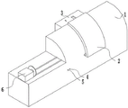
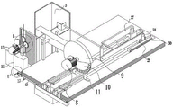
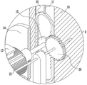
Referring to fig. 1-2, a cutting and polishing integrated device for a steel bar for building engineering and a using method thereof, includes a device housing 1, a glass door 2 is slidably mounted on an outer wall of the device housing 1, a first supporting plate 54 is fixedly mounted on an inner wall of the device housing 1, a power device 3 is disposed on a side wall of the device housing 1, a feed inlet 7 is disposed on one side of the device housing 1, a steel bar 53 is slidably mounted on an inner wall of the feed inlet 7, a clamp 52 is slidably mounted on an outer wall of the steel bar 53, a first switch 4 and a second switch 5 are fixedly mounted on the other side of the device housing 1, input ends of a first motor 8 and a second motor 13 are electrically connected with output ends of the switch 4 and the switch 5 through wires, input ends of the switch 4 and the switch 5 are electrically connected with an external power source through wires, a polishing device 6 is disposed on a top end of one side of the device housing 1, and a power mechanism is mounted on an inner wall of the power device 3, a saw blade 10 is arranged above the steel bar 53, a protective shell 9 is fixedly mounted on the outer wall of the saw blade 10, a first motor 8 is fixedly mounted on the side wall of the protective shell 9, a second connecting rod 19 is fixedly mounted on the side wall of the protective shell 9, a first square groove 11 is formed below the steel bar 53, and the first square groove 11 is formed in the inner wall of the first supporting plate 54; through the first slide mechanism who sets up, pushing mechanism and fixture mutually support, when the device moves, can press switch second switch 5, start second motor 13, second motor 13 drives first half-tooth gear 14 and rotates, first half-tooth gear 14 drives first slide mechanism motion, first half-tooth gear 14 drives pushing mechanism and fixture intermittent type formula motion, avoided when the cutting, because the reinforcing bar 53 of cutting at every turn is more, consequently, need repeat the position to reinforcing bar 53 to adjust, because manual needs mark reinforcing bar 53, the fixed steel bar 53, cutting reinforcing bar 53, the process is too loaded down with trivial details, lead to the lower problem of reinforcing bar 53 cutting efficiency, the work efficiency of device has been improved.
A cutting and polishing integrated device for a steel bar for building engineering and a using method thereof comprise the following steps:
s1, in the building, the steel bar 53 is usually used in concrete, the earthquake resistance of the building can be enhanced, but the steel bar 53 needs to be cut into the same length for use, a worker opens the glass door 2 in the first step, the steel bar 53 with qualified length is placed in the middle of the clamp 52, the distance is adjusted again, the fourth connecting rod 48 is pulled, the fourth connecting rod 48 moves from the inner wall of the fifth connecting rod 49, the stop block 51 can become one end of the steel bar 53, the other end of the steel bar 53 reaches the position below the saw blade 10, and then the fixing screw 50 is rotated, so that one end of the fixing screw 50 extrudes the fourth connecting rod 48 to fix the fourth connecting rod, and then the steel bar 53 is placed in the inner wall of the feed port 7;
s2, in the second step, the first switch 4 and the second switch 5 are pressed to be switched on and switched off, so that the first motor 8 and the second motor 13 are started, the first motor 8 drives the saw blade 10 to rotate, the second motor 13 drives the first half-toothed gear 14 to rotate, the first half-toothed gear 14 drives the second half-toothed gear 15 to rotate, the second half-toothed gear 15 drives the integrated rack plate 16 to slide up and down on the inner wall of the second supporting block 18, the integrated rack plate 16 drives the first connecting rod 17 to move, the first connecting rod 17 at one end drives the second connecting rod 19 to move because the first connecting rod 17 is L-shaped, so that the second connecting rod 19 drives the protective shell 9 to move back and forth to realize repeated cutting, meanwhile, the first half-toothed gear 14 drives the first gear 20 to rotate, the first gear 20 drives the first round rod 21 to rotate, the first round rod 21 drives the first conical gear 22 to rotate, the first conical gear 22 drives the second conical gear 23 to rotate, the second bevel gear 23 drives the second circular rod 25 to rotate, the second circular rod 25 drives the first connecting plate 26 to rotate, the first connecting plate 26 drives the second connecting plate 27 to rotate, the second connecting plate 27 rotates to incline the bearing seat 28, the bearing seat 28 drives the sliding device 29 to move, the reinforcing steel bar 53 continues to move forward for a distance when the bearing seat 28 returns through an elastic pad at the bottom of the bearing seat 28, so that the sliding device 29 drives the reinforcing steel bar 53 to move, the first circular rod 21 drives the third bevel gear 33 to rotate, the third bevel gear 33 drives the fourth bevel gear 34 to rotate, the fourth bevel gear 34 drives the third circular rod 35 to rotate, the third circular rod 35 drives the fifth bevel gear 38 to rotate, the fifth bevel gear 38 drives the sixth bevel gear 39 to rotate, the sixth bevel gear 39 drives the fourth circular rod 40 to rotate, the fourth circular rod 40 drives the third connecting plate 41 to rotate, the third connecting plate 41 drives the first rack plate 42 to slide on the inner wall of the third supporting block 44, the first rack plate 42 drives the second gear 43 to rotate, the second gear 43 drives the threaded rod 45 to rotate, the threaded rod 45 drives the sliding blocks 47 to slide on the inner wall of the fourth supporting block 46, and the threads on the surface of the threaded rod 45 are opposite, so that the two sliding blocks 47 slide relatively, and the reinforcing steel bar 53 is clamped;
s3: and thirdly, the steel bars 53 are led to the grinding device 6 through the rail to be ground, and finally the cut and ground steel bars 53 are pulled to a construction site to be used.
Example two
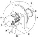
Referring to fig. 3 to 10, as another embodiment of the present invention, a first power mechanism includes a first supporting block 12 installed on an inner wall of a power device 3, a second motor 13 is fixedly installed at a top end of the first supporting block 12, a first half-tooth gear 14 is fixedly installed on a side wall of the second motor 13, a first sliding mechanism is installed on a side wall of the first half-tooth gear 14, and a rotating mechanism is installed on the other side of the first half-tooth gear 14; through the power unit who sets up, when needing the device to provide power, can press switch second switch 5, start second motor 13, second motor 13 drives first pinion gear 14 and rotates to for first slide mechanism and slewing mechanism provide power, provide automatic function for the device.
The first sliding mechanism comprises a second half-toothed gear 15 arranged on the side wall of the first half-toothed gear 14, an integrated rack plate 16 is arranged on the side wall of the second half-toothed gear 15, the second half-toothed gear 15 is meshed with the integrated rack plate 16, first connecting rods 17 are fixedly arranged on the upper side and the lower side of the integrated rack plate 16, one of the first connecting rods 17 is L-shaped, a second supporting block 18 is fixedly arranged at one end of each first connecting rod 17, and a second connecting rod 19 is fixedly arranged at one end of each second supporting block 18; through the first slide mechanism who sets up, when the cutting, start second motor 13, second motor 13 rotates and drives cutting equipment and reciprocate to cutting reinforcing bar 53, power is provided for the cutting of reinforcing bar 53, avoided current reinforcing bar 53 cutting equipment when cutting reinforcing bar 53, after the cutting at every turn, all need artifical manual position to reinforcing bar 53 to adjust, very troublesome problem has improved the convenience of device, automatic cutting has been realized.
The rotating mechanism comprises a first gear 20 arranged on the side wall of the first half-tooth gear 14, the first half-tooth gear 14 is meshed with the first gear 20, a first round bar 21 is fixedly arranged on the inner wall of the first gear 20, a first conical gear 22 is fixedly arranged at one end of the first round bar 21, a second conical gear 23 is arranged on the side wall of the first conical gear 22, the first conical gear 22 is meshed with the second conical gear 23, a second round bar 25 is fixedly arranged on the side wall of the second conical gear 23, one end of the first round bar 21 is fixedly connected with one end of the second round bar 25 through a first fixing plate 24, a second sliding mechanism is arranged at one end of the first round bar 21, and a pushing mechanism is arranged at one end of the second round bar 25; through the slewing mechanism who sets up, when needing to provide power for pushing mechanism, can press switch second switch 5, start second motor 13, second motor 13 drives first half-tooth gear 14 and rotates, first half-tooth gear 14 drives first gear 20 and rotates, first gear 20 drives first round bar 21 and rotates, first round bar 21 drives first conical gear 22 and rotates, first conical gear 22 drives second conical gear 23 and rotates, second conical gear 23 drives second round bar 25 and rotates, thereby drive pushing mechanism and slide, realize the automation of device.
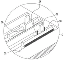
The pushing mechanism comprises a first connecting plate 26 installed at one end of a second round rod 25, a second connecting plate 27 is installed at one end of the first connecting plate 26, a third connecting rod 32 is fixedly installed on the side wall of the second connecting plate 27, pushing devices are installed on two sides of the third connecting rod 32, the first connecting plate 26 is connected with the second connecting plate 27 through a bearing, bearing seats 28 are installed on two sides of one end of the second connecting plate 27, the bearing seats 28 are connected with the second connecting plate 27 through a bearing, an elastic cushion is attached to the bottom of each bearing seat 28, sliding devices 29 are installed on the outer walls of the bearing seats 28, the bearing seats 28 are connected with the sliding devices 29 through bearings, the sliding devices 29 are convex, round grooves 30 are formed in the inner walls of the sliding devices 29, reinforcing steel bars 53 are installed on the outer walls of the round grooves 30, the reinforcing steel bars 53 slide on the inner walls of the round grooves 30, the bottom ends of the sliding devices 29 are embedded in the inner walls of second square grooves 31, the second square groove 31 is arranged on the inner wall of the first supporting plate 54; through the pushing mechanism who sets up, when removing reinforcing bar 53, start second motor 13, second motor 13 drives pushing mechanism round trip movement, thereby remove reinforcing bar 53, through the third connecting rod 32 that sets up, can realize that two thrust unit drive reinforcing bar 53 and remove simultaneously, provide power for the reinforcing bar 53 pay-off, when having avoided current reinforcing bar 53 cutting equipment to remove, remove at every turn, need manually remove reinforcing bar 53, very troublesome problem, the production efficiency of device has been improved.
The second sliding mechanism comprises a third bevel gear 33 arranged at one end of the first round bar 21, a fourth bevel gear 34 is arranged on the side wall of the third bevel gear 33, the third bevel gear 33 is engaged with the fourth bevel gear 34, a third round bar 35 is fixedly arranged at the bottom end of the fourth bevel gear 34, one end of the first round bar 21 is fixedly connected with one end of the third round bar 35 through a second fixing plate 36, a fifth bevel gear 38 is fixedly arranged at one end of the third round bar 35, a sixth bevel gear 39 is arranged on the side wall of the fifth bevel gear 38, the fifth bevel gear 38 is engaged with the sixth bevel gear 39, a fourth round bar 40 is fixedly arranged on the inner wall of the sixth bevel gear 39, one end of the third round bar 35 is fixedly connected with one end of the fourth round bar 40 through a third fixing plate 37, a third connecting plate 41 is fixedly arranged at one end of the fourth round bar 40, and a first rack plate 42 is arranged at one end of the third connecting plate 41, the third connecting plate 41 is connected with the first rack plate 42 through a bearing, a second gear 43 is mounted on the side wall of the first rack plate 42, the first rack plate 42 is meshed with the second gear 43, a third supporting block 44 is mounted on the outer wall of the second gear 43, the second gear 43 is connected with the third supporting block 44 through a bearing, one side of the third supporting block 44 is fixed on the side wall of the first supporting plate 54, and a clamping mechanism is fixedly mounted on the side wall of the second gear 43; through the second sliding mechanism, when power needs to be supplied to the clamping mechanism, the second switch 5 can be pressed to start the second motor 13, the second motor 13 drives the first half-toothed gear 14 to rotate, the first half-toothed gear 14 drives the first gear 20 to rotate, the first gear 20 drives the first round bar 21 to rotate, the first round bar 21 drives the third conical gear 33 to rotate, the third conical gear 33 drives the fourth conical gear 34 to rotate, the fourth conical gear 34 drives the third round bar 35 to rotate, the third round bar 35 drives the fifth conical gear 38 to rotate, the fifth conical gear 38 drives the sixth conical gear 39 to rotate, the sixth conical gear 39 drives the fourth round bar 40 to rotate, the fourth round bar 40 drives the third connecting plate 41 to rotate, the third connecting plate 41 drives the first rack plate 42 to slide on the inner wall of the third supporting block 44, the first rack plate 42 drives the second gear 43 to rotate, thereby the second gear 43 drives the clamping mechanism to move, and the automation of the device is realized.
EXAMPLE III
Referring to fig. 11, in a first comparative example, as another embodiment of the present invention, a clamping mechanism includes a threaded rod 45 installed on a side wall of the second gear 43, four sliding blocks 47 are installed on an outer wall of the threaded rod 45, and a telescopic mechanism is fixedly installed at a top end of the sliding block 47; through the fixture who sets up, when pressing from both sides tight reinforcing bar 53, start second motor 13, second motor 13 drives clamping device and removes toward reinforcing bar 53 center to it is fixed to reinforcing bar 53, when having avoided fixing reinforcing bar 53, need the manual work to fix repeatedly, very troublesome problem has improved the convenience of device, has improved the work efficiency of device.
The telescopic mechanism comprises a fourth connecting rod 48 arranged at the top end of the sliding block 47, a fifth connecting rod 49 is arranged on the outer wall of the fourth connecting rod 48 in a sliding mode, and the fourth connecting rod 48 slides on the inner wall of the fifth connecting rod 49; through the telescopic machanism who sets up, when needing 53 test length to the required reinforcing bar of production, can stimulate fourth connecting rod 48, fourth connecting rod 48 removes from the inner wall of fifth connecting rod 49, and stopper 51 can become the one end of reinforcing bar 53, and the other end of reinforcing bar 53 reaches the below of saw bit 10 can, avoided the workman need mark the problem of reinforcing bar 53 length repeatedly, improved work efficiency.
The outer walls of the fifth connecting rods 49 are provided with fixing screws 50, the fifth connecting rods 49 are in threaded connection with the fixing screws 50, and the outer walls of the four fifth connecting rods 49 are provided with the fixing screws 50 and are in threaded connection; through the set screw 50 who sets up, can rotate set screw 50 when reaching the required length of reinforcing bar 53 to the one end extrusion fourth connecting rod 48 of set screw 50 makes it fixed, has avoided the workman to need mark the problem of reinforcing bar 53 length repeatedly, has improved work efficiency.
Theory of operation, in reinforcing bar 53 in the building commonly used with the concrete, can strengthen the earthquake resistance of building, but reinforcing bar 53 need cut into the same length just can use, first step workman opens glass door 2, put the reinforcing bar 53 of qualified length in the centre of anchor clamps 52, readjust the interval, pulling fourth connecting rod 48, fourth connecting rod 48 removes from the inner wall of fifth connecting rod 49, stopper 51 can become the one end of reinforcing bar 53, the other end of reinforcing bar 53 reach the below of saw bit 10 can, rotate set screw 50 again, thereby set screw 50's one end extrusion fourth connecting rod 48, make it fixed, put reinforcing bar 53 into the inner wall of feed inlet 7 again.
Secondly, the first switch 4 and the second switch 5 are pressed to start the first motor 8 and the second motor 13, the first motor 8 drives the saw blade 10 to rotate, the second motor 13 drives the first half-toothed gear 14 to rotate, the first half-toothed gear 14 drives the second half-toothed gear 15 to rotate, the second half-toothed gear 15 drives the integrated rack plate 16 to slide up and down on the inner wall of the second supporting block 18, the integrated rack plate 16 drives the first connecting rod 17 to move, the first connecting rod 17 at one end drives the second connecting rod 19 to move, so that the second connecting rod 19 drives the protective shell 9 to move back and forth to realize repeated cutting, meanwhile, the first half-toothed gear 14 drives the first gear 20 to rotate, the first gear 20 drives the first round rod 21 to rotate, the first round rod 21 drives the first conical gear 22 to rotate, the first conical gear 22 drives the second conical gear 23 to rotate, the second bevel gear 23 drives the second circular rod 25 to rotate, the second circular rod 25 drives the first connecting plate 26 to rotate, the first connecting plate 26 drives the second connecting plate 27 to rotate, the second connecting plate 27 rotates to incline the bearing seat 28, the bearing seat 28 drives the sliding device 29 to move, the reinforcing steel bar 53 continues to move forward for a distance when the bearing seat 28 returns through an elastic pad at the bottom of the bearing seat 28, so that the sliding device 29 drives the reinforcing steel bar 53 to move, the first circular rod 21 drives the third bevel gear 33 to rotate, the third bevel gear 33 drives the fourth bevel gear 34 to rotate, the fourth bevel gear 34 drives the third circular rod 35 to rotate, the third circular rod 35 drives the fifth bevel gear 38 to rotate, the fifth bevel gear 38 drives the sixth bevel gear 39 to rotate, the sixth bevel gear 39 drives the fourth circular rod 40 to rotate, the fourth circular rod 40 drives the third connecting plate 41 to rotate, the third connecting plate 41 drives the first rack plate 42 to slide on the inner wall of the third supporting block 44, the first rack plate 42 drives the second gear 43 to rotate, the second gear 43 drives the threaded rod 45 to rotate, the threaded rod 45 drives the sliding block 47 to slide on the inner wall of the fourth supporting block 46, and the threads on the surface of the threaded rod 45 are opposite, so that the two sliding blocks 47 slide relatively, and the reinforcing steel bar 53 is clamped.
And thirdly, the reinforcing steel bars 53 are led to the grinding device 6 through the rail to be ground, and finally the cut and ground reinforcing steel bars 53 are pulled to a construction site for use.
In the description herein, references to the description of "one embodiment," "an example," "a specific example" or the like are intended to mean that a particular feature, structure, material, or characteristic described in connection with the embodiment or example is included in at least one embodiment or example of the invention. In this specification, the schematic representations of the terms used above do not necessarily refer to the same embodiment or example. Furthermore, the particular features, structures, materials, or characteristics described may be combined in any suitable manner in any one or more embodiments or examples.
The foregoing shows and describes the general principles, essential features, and advantages of the invention. It will be understood by those skilled in the art that the present invention is not limited to the embodiments described above, which are described in the specification and illustrated only to illustrate the principle of the present invention, but that various changes and modifications may be made therein without departing from the spirit and scope of the present invention, which fall within the scope of the invention as claimed.