CN114892754A - Sponge city system and building method thereof - Google Patents
Sponge city system and building method thereof Download PDFInfo
- Publication number
- CN114892754A CN114892754A CN202210359590.1A CN202210359590A CN114892754A CN 114892754 A CN114892754 A CN 114892754A CN 202210359590 A CN202210359590 A CN 202210359590A CN 114892754 A CN114892754 A CN 114892754A
- Authority
- CN
- China
- Prior art keywords
- water
- wall
- collecting tank
- tank
- water collecting
- Prior art date
- Legal status (The legal status is an assumption and is not a legal conclusion. Google has not performed a legal analysis and makes no representation as to the accuracy of the status listed.)
- Pending
Links
- 238000000034 method Methods 0.000 title claims abstract description 11
- XLYOFNOQVPJJNP-UHFFFAOYSA-N water Substances O XLYOFNOQVPJJNP-UHFFFAOYSA-N 0.000 claims abstract description 176
- 230000007246 mechanism Effects 0.000 claims abstract description 34
- 238000011068 loading method Methods 0.000 claims abstract description 29
- 238000010276 construction Methods 0.000 claims abstract description 11
- 241000894006 Bacteria Species 0.000 claims abstract description 10
- 239000007787 solid Substances 0.000 claims abstract description 10
- 230000000694 effects Effects 0.000 claims abstract description 9
- 239000002699 waste material Substances 0.000 claims abstract description 8
- 239000002253 acid Substances 0.000 claims abstract description 7
- 230000015572 biosynthetic process Effects 0.000 claims abstract description 7
- 239000000126 substance Substances 0.000 claims abstract description 7
- 239000003513 alkali Substances 0.000 claims abstract description 6
- 239000003673 groundwater Substances 0.000 claims abstract description 3
- 239000007921 spray Substances 0.000 claims description 24
- 239000002184 metal Substances 0.000 claims description 22
- 230000005540 biological transmission Effects 0.000 claims description 13
- 238000010438 heat treatment Methods 0.000 claims description 12
- 238000003756 stirring Methods 0.000 claims description 11
- 239000012535 impurity Substances 0.000 claims description 10
- 238000009434 installation Methods 0.000 claims description 9
- 238000005192 partition Methods 0.000 claims description 9
- 239000007788 liquid Substances 0.000 claims description 8
- 238000007789 sealing Methods 0.000 claims description 8
- 239000002689 soil Substances 0.000 claims description 8
- 230000006835 compression Effects 0.000 claims description 4
- 238000007906 compression Methods 0.000 claims description 4
- 238000006243 chemical reaction Methods 0.000 claims description 3
- 238000005470 impregnation Methods 0.000 claims description 3
- 238000012545 processing Methods 0.000 claims description 3
- 238000005086 pumping Methods 0.000 claims description 2
- 238000001556 precipitation Methods 0.000 abstract description 6
- 238000000354 decomposition reaction Methods 0.000 abstract description 3
- 230000001954 sterilising effect Effects 0.000 abstract 1
- 238000004659 sterilization and disinfection Methods 0.000 abstract 1
- 230000032258 transport Effects 0.000 description 19
- 238000005516 engineering process Methods 0.000 description 5
- 238000011161 development Methods 0.000 description 3
- 230000007613 environmental effect Effects 0.000 description 3
- 230000008569 process Effects 0.000 description 3
- 238000009825 accumulation Methods 0.000 description 2
- 210000000232 gallbladder Anatomy 0.000 description 2
- 239000000463 material Substances 0.000 description 2
- 238000010521 absorption reaction Methods 0.000 description 1
- 150000007513 acids Chemical class 0.000 description 1
- 230000003796 beauty Effects 0.000 description 1
- 230000009286 beneficial effect Effects 0.000 description 1
- 238000009435 building construction Methods 0.000 description 1
- 229910052799 carbon Inorganic materials 0.000 description 1
- 230000007547 defect Effects 0.000 description 1
- 238000001704 evaporation Methods 0.000 description 1
- 230000005012 migration Effects 0.000 description 1
- 238000013508 migration Methods 0.000 description 1
- 238000000746 purification Methods 0.000 description 1
- 230000009467 reduction Effects 0.000 description 1
- 230000029058 respiratory gaseous exchange Effects 0.000 description 1
- 238000001179 sorption measurement Methods 0.000 description 1
- 238000006467 substitution reaction Methods 0.000 description 1
- 239000002352 surface water Substances 0.000 description 1
- 239000011573 trace mineral Substances 0.000 description 1
- 235000013619 trace mineral Nutrition 0.000 description 1
- 238000012546 transfer Methods 0.000 description 1
Images




Classifications
-
- E—FIXED CONSTRUCTIONS
- E03—WATER SUPPLY; SEWERAGE
- E03B—INSTALLATIONS OR METHODS FOR OBTAINING, COLLECTING, OR DISTRIBUTING WATER
- E03B3/00—Methods or installations for obtaining or collecting drinking water or tap water
- E03B3/02—Methods or installations for obtaining or collecting drinking water or tap water from rain-water
-
- C—CHEMISTRY; METALLURGY
- C02—TREATMENT OF WATER, WASTE WATER, SEWAGE, OR SLUDGE
- C02F—TREATMENT OF WATER, WASTE WATER, SEWAGE, OR SLUDGE
- C02F1/00—Treatment of water, waste water, or sewage
- C02F1/001—Processes for the treatment of water whereby the filtration technique is of importance
-
- C—CHEMISTRY; METALLURGY
- C02—TREATMENT OF WATER, WASTE WATER, SEWAGE, OR SLUDGE
- C02F—TREATMENT OF WATER, WASTE WATER, SEWAGE, OR SLUDGE
- C02F1/00—Treatment of water, waste water, or sewage
- C02F1/02—Treatment of water, waste water, or sewage by heating
-
- E—FIXED CONSTRUCTIONS
- E02—HYDRAULIC ENGINEERING; FOUNDATIONS; SOIL SHIFTING
- E02D—FOUNDATIONS; EXCAVATIONS; EMBANKMENTS; UNDERGROUND OR UNDERWATER STRUCTURES
- E02D3/00—Improving or preserving soil or rock, e.g. preserving permafrost soil
- E02D3/02—Improving by compacting
- E02D3/10—Improving by compacting by watering, draining, de-aerating or blasting, e.g. by installing sand or wick drains
-
- E—FIXED CONSTRUCTIONS
- E03—WATER SUPPLY; SEWERAGE
- E03F—SEWERS; CESSPOOLS
- E03F5/00—Sewerage structures
- E03F5/10—Collecting-tanks; Equalising-tanks for regulating the run-off; Laying-up basins
-
- E—FIXED CONSTRUCTIONS
- E03—WATER SUPPLY; SEWERAGE
- E03F—SEWERS; CESSPOOLS
- E03F5/00—Sewerage structures
- E03F5/14—Devices for separating liquid or solid substances from sewage, e.g. sand or sludge traps, rakes or grates
-
- E—FIXED CONSTRUCTIONS
- E03—WATER SUPPLY; SEWERAGE
- E03F—SEWERS; CESSPOOLS
- E03F5/00—Sewerage structures
- E03F5/22—Adaptations of pumping plants for lifting sewage
-
- C—CHEMISTRY; METALLURGY
- C02—TREATMENT OF WATER, WASTE WATER, SEWAGE, OR SLUDGE
- C02F—TREATMENT OF WATER, WASTE WATER, SEWAGE, OR SLUDGE
- C02F2103/00—Nature of the water, waste water, sewage or sludge to be treated
- C02F2103/001—Runoff or storm water
-
- Y—GENERAL TAGGING OF NEW TECHNOLOGICAL DEVELOPMENTS; GENERAL TAGGING OF CROSS-SECTIONAL TECHNOLOGIES SPANNING OVER SEVERAL SECTIONS OF THE IPC; TECHNICAL SUBJECTS COVERED BY FORMER USPC CROSS-REFERENCE ART COLLECTIONS [XRACs] AND DIGESTS
- Y02—TECHNOLOGIES OR APPLICATIONS FOR MITIGATION OR ADAPTATION AGAINST CLIMATE CHANGE
- Y02A—TECHNOLOGIES FOR ADAPTATION TO CLIMATE CHANGE
- Y02A30/00—Adapting or protecting infrastructure or their operation
- Y02A30/60—Planning or developing urban green infrastructure
Landscapes
- Engineering & Computer Science (AREA)
- Life Sciences & Earth Sciences (AREA)
- Water Supply & Treatment (AREA)
- Hydrology & Water Resources (AREA)
- Public Health (AREA)
- Health & Medical Sciences (AREA)
- Environmental & Geological Engineering (AREA)
- Structural Engineering (AREA)
- Organic Chemistry (AREA)
- Chemical & Material Sciences (AREA)
- Agronomy & Crop Science (AREA)
- Soil Sciences (AREA)
- General Life Sciences & Earth Sciences (AREA)
- Mining & Mineral Resources (AREA)
- Paleontology (AREA)
- Civil Engineering (AREA)
- General Engineering & Computer Science (AREA)
- Processing Of Solid Wastes (AREA)
Abstract
本发明公开了一种海绵城市系统及其搭建方法,包括:第一聚水箱,所述第一聚水箱的顶部固定安装有开槽挡板,所述开槽挡板的外壁一侧分别设置有废渣处理机构、水流增压机构和地面供水机构,所述废渣供水机构包括装载筒,本系统设备采用分布对雨水处理的方式,将进入设备中混合水源进入高温的加热,提高细菌的分子活性,同时利用驱动部件加速分子结构的分解,使酸碱物质逐步降解,生成的残渣固体进行快速过滤,再储存到第二聚水箱中供城市其他区域进行加湿,有效解决现有设备因只能进行水源的储存和后期对水源的倒运,而无法在雨水收集前进行灭菌处理的问题,避免储存的水源污染较大造成水源再次蒸发后形成污染性降水。

The invention discloses a sponge city system and a construction method thereof, comprising: a first water collecting tank, a slotted baffle is fixedly installed on the top of the first water collecting tank, and one side of the outer wall of the slotted baffle is respectively provided with Waste residue treatment mechanism, water flow pressurization mechanism and ground water supply mechanism. The waste residue water supply mechanism includes a loading cylinder. The system equipment adopts the method of distributed rainwater treatment, and the mixed water source entering the equipment is heated at high temperature to improve the molecular activity of bacteria. At the same time, the driving components are used to accelerate the decomposition of the molecular structure, so that the acid and alkali substances are gradually degraded, and the generated residual solids are quickly filtered, and then stored in the second water collecting tank for humidification in other areas of the city, effectively solving the problem that the existing equipment can only use water source The problem of sterilization treatment before rainwater collection can not be carried out, so as to avoid the pollution of the stored water source and the formation of polluted precipitation after the water source evaporates again.
Description
技术领域technical field
本发明涉及海绵城市领域,更具体的,涉及一种海绵城市系统及其搭建方法。The invention relates to the field of sponge cities, and more particularly, to a sponge city system and a construction method thereof.
背景技术Background technique
海绵城市,是新一代城市雨洪管理概念,是指城市能够像海绵一样,在适应环境变化和应对雨水带来的自然灾害等方面具有良好的弹性,也可称之为“水弹性城市”,国际通用术语为“低影响开发雨水系统构建”,下雨时吸水、蓄水、渗水、净水,需要时将蓄存的水释放并加以利用,实现雨水在城市中自由迁移,而从生态系统服务出发,通过跨尺度构建水生态基础设施,并结合多类具体技术建设水生态基础设施,是海绵城市的核心,在新形势下,海绵城市是推动绿色建筑建设,低碳城市发展,智慧城市形成的创新表现,是现代绿色新技术与社会、环境、人文等多种因素下的有机结合,“海绵城市”材料实质性应用,表现出优秀的渗水、抗压、耐磨、防滑以及环保美观多彩、舒适易维护和吸音减噪等特点,成了“会呼吸”的城镇景观路面,也有效缓解了城市热岛效应,让城市路面不再发热。Sponge city is a new generation of urban stormwater management concept. It means that the city can be like a sponge and has good flexibility in adapting to environmental changes and responding to natural disasters caused by rainwater. It can also be called a "water elastic city". The international term is "low-impact development of rainwater system construction", which absorbs, stores, seeps and purifies water when it rains, and releases and utilizes the stored water when needed, so as to realize the free migration of rainwater in the city, and the free movement of rainwater from the ecosystem. Starting from services, building water ecological infrastructure across scales and combining various types of specific technologies to build water ecological infrastructure is the core of sponge city. Under the new situation, sponge city is to promote green building construction, low-carbon city development, and smart city. The innovative performance formed is the organic combination of modern green new technology and social, environmental, humanistic and other factors. The material application of "sponge city" material shows excellent water seepage, compression resistance, wear resistance, anti-skid and environmental protection and beauty. Colorful, comfortable and easy to maintain, sound absorption and noise reduction, etc., it has become a "breathing" urban landscape pavement, and it also effectively alleviates the urban heat island effect, so that the urban pavement no longer heats up.
随着科学技术的发展,人们能更加有效的水资源进行控制,并充分利用到城市的基础建设中,进而提出海绵城市的理念,有方法地将雨天所降落的水源储存起来,供其他区域进行使用。With the development of science and technology, people can control water resources more effectively and make full use of it in the urban infrastructure, and then put forward the concept of sponge city, which can store the water that falls on rainy days in a way for other areas to carry out use.
但现有城市系统中由于城市环境中会存在大量有害物质及强酸强碱等微量元素,当与水汇合后,再次利用时,蒸发至大气环境中,会造成某区域产生污染性降水的隐患。However, in the existing urban system, there are a large number of harmful substances and trace elements such as strong acids and alkalis in the urban environment. When they are combined with water and reused, they will evaporate into the atmospheric environment, causing the hidden danger of polluting precipitation in a certain area.
发明内容SUMMARY OF THE INVENTION
本发明所要解决的技术问题在于现有系统设备,无法处理掺杂在雨水中的有害杂质,导致污染水源再次蒸发时,造成局部区域内产生污染降水的问题。为了克服现有技术的缺陷,本发明提出一种海绵城市系统及其搭建方法,其能够避免储存的水源污染较大造成水源再次蒸发后形成污染性降水。The technical problem to be solved by the present invention is that the existing system equipment cannot handle the harmful impurities mixed in the rainwater, resulting in the problem of polluted precipitation in a local area when the polluted water source evaporates again. In order to overcome the defects of the prior art, the present invention proposes a sponge city system and a construction method thereof, which can avoid the formation of polluted precipitation after the re-evaporation of the water source due to the large pollution of the stored water source.
为达此目的,本发明采用以下技术方案:For this purpose, the present invention adopts the following technical solutions:
本发明提供了一种海绵城市系统,包括:第一聚水箱,所述第一聚水箱的顶部固定安装有开槽挡板,所述开槽挡板的外壁一侧分别设置有废渣处理机构、水流增压机构和地面供水机构;The present invention provides a sponge city system, comprising: a first water collecting tank, a slotted baffle is fixedly installed on the top of the first water collecting tank, and a waste residue treatment mechanism, a Water pressurization mechanism and surface water supply mechanism;
所述废渣供水机构包括装载筒,所述装载筒的内壁底部固定安装有金属安装架,所述金属安装架的内表壁固定插设有伺服电机,所述第一聚水箱的内表壁固定安装有三个内接环,三个所述内接环其中每个的内表壁均固定插设有一组支撑杆,三组所述支撑杆的外表壁之间固定套设有内胆,所述伺服电机的输出端固定安装有传动杆,所述传动杆的顶部贯穿内胆的底部,并位于内胆的内部,所述传动杆的外表壁固定套设有转盘,所述转盘的内部固定插设有多个延伸杆,多个所述延伸杆其中每个的顶部均焊接有搅拌杆,三个所述内接环的内部均开设有一组安装环槽,三组所述安装环槽其中每三个的内表壁之间均固定安装有加热棒。The waste residue water supply mechanism includes a loading cylinder, the bottom of the inner wall of the loading cylinder is fixedly installed with a metal mounting frame, the inner surface wall of the metal mounting frame is fixedly inserted with a servo motor, and the inner surface wall of the first water collecting tank is fixed Three inscribed rings are installed, and a set of support rods are fixedly inserted into the inner surface wall of each of the three inscribed rings, and an inner bladder is fixedly sleeved between the outer walls of the three sets of the support rods. The output end of the servo motor is fixedly installed with a transmission rod. The top of the transmission rod penetrates the bottom of the inner tank and is located inside the inner tank. There are a plurality of extension rods, and the top of each of the plurality of extension rods is welded with a stirring rod, and a set of installation ring grooves are opened in the interior of the three inscribed rings, and each of the three sets of the installation ring grooves is A heating rod is fixedly installed between the three inner surface walls.
在本发明较佳的技术方案中,所述水流增压机构包括加压箱,所述加压箱的内壁两侧均固定安装有滑道,两个所述滑道的内表壁之间活动插设有过滤板。In a preferred technical solution of the present invention, the water flow pressurization mechanism includes a pressurized box, and slideways are fixedly installed on both sides of the inner wall of the pressurized box, and the inner surface walls of the two slideways are movable between the inner surfaces of the two slideways. A filter plate is inserted.
在本发明较佳的技术方案中,所述加压箱的内壁底部固定安装有衔接板,所述衔接板的内部固定安装有连接环所述连接环的内表壁固定插设有水泵,所述加压箱的内壁两侧之间固定安装有隔板,所述隔板将加压箱的内部分割成两个区域。In a preferred technical solution of the present invention, a connecting plate is fixedly installed at the bottom of the inner wall of the pressurized box, and a connecting ring is fixedly installed inside the connecting plate, and a water pump is fixedly inserted into the inner surface wall of the connecting ring, so A partition plate is fixedly installed between two sides of the inner wall of the pressurized box, and the partition plate divides the interior of the pressurized box into two regions.
在本发明较佳的技术方案中,所述水泵的输出端贯穿隔板的外壁一侧,并与其中一个区域相连通,所述加压箱的外壁一侧固定连通有第二运水道,所述水泵的输出端固定连通有第三运水道。In a preferred technical solution of the present invention, the output end of the water pump penetrates one side of the outer wall of the partition plate and communicates with one of the regions. The output end of the water pump is fixedly connected with a third water channel.
在本发明较佳的技术方案中,所述供水机构包括第二聚水箱,所述第二聚水箱的顶部设置有顶盖,所述顶盖的顶部开设有多个圆孔,多个所述圆孔其中每个的直径数值均相等。In a preferred technical solution of the present invention, the water supply mechanism includes a second water collecting tank, a top cover is provided on the top of the second water collecting tank, and a plurality of circular holes are opened on the top of the top cover, and a plurality of the Each of the circular holes has an equal diameter value.
在本发明较佳的技术方案中,多个所述圆孔的内表壁均固定安装有喷枪,多个所述喷枪其中每个的输入端均固定连通有通水管。In a preferred technical solution of the present invention, spray guns are fixedly installed on the inner surface walls of the plurality of circular holes, and a water passage is fixedly connected to the input end of each of the plurality of spray guns.
在本发明较佳的技术方案中,所述装载筒的顶部开设有凹槽,所述凹槽的内壁两侧之间固定插设有金属杆,所述金属杆的外表壁活动套设有U型架,所述U型架的外表壁固定安装有密封盖。In a preferred technical solution of the present invention, a groove is formed on the top of the loading cylinder, a metal rod is fixedly inserted between two sides of the inner wall of the groove, and the outer wall of the metal rod is movably sleeved with a U. The outer wall of the U-shaped frame is fixedly installed with a sealing cover.
在本发明较佳的技术方案中,所述开槽挡板的外壁一侧固定连通有第一运水管道,所述第一运水管道的出水端贯穿装载筒和内胆的外表壁,并与内胆的内部相连通,所述第二运水道的进水端贯穿装载筒和内胆的外表壁,并与装载筒的内部相连通,所述第三运水道的出水端和第二聚水箱的外壁一侧相连通。In a preferred technical solution of the present invention, a first water transport pipe is fixedly connected to one side of the outer wall of the slotted baffle plate, and the water outlet end of the first water transport pipe penetrates the outer wall of the loading cylinder and the inner tank, and It is communicated with the interior of the inner tank, the water inlet end of the second water transport channel runs through the outer wall of the loading cylinder and the inner bladder, and is communicated with the interior of the loading cylinder, and the water outlet end of the third water transport channel is connected to the second collector. One side of the outer wall of the water tank is communicated.
一种海绵城市系统的搭建方法,包括以下步骤:A method for building a sponge city system, comprising the following steps:
步骤一:首先将第一聚水箱、装载筒、加压箱和第二聚水箱埋入地层中,其中第一聚水箱、装载筒和第二聚水箱的顶部裸露在地表上,并将第一聚水箱顶部的开槽挡板放置在雨水流动下游。Step 1: First, bury the first water collecting tank, the loading drum, the pressurizing tank and the second water collecting tank into the ground, wherein the tops of the first water collecting tank, the loading drum and the second water collecting tank are exposed on the ground, and the first A slotted baffle at the top of the collecting tank is placed downstream of the rainwater flow.
步骤二:当雨水通过开槽挡板上的槽洞,流入到第一聚水箱中后,由于液体体积的增加,使得第一运水管道中具备较高的压强,并冲击进内胆中,进入到内胆中雨水掺杂有固体杂质及有害细菌,通过机构中的加热元件,提高有害细菌的分子活性,同时使强酸碱物质在高温的影响下快速分解,同时利用机构中的传动部件,对雨水进行搅拌,加速反应效率。Step 2: When the rainwater flows into the first water collecting tank through the slot on the slotted baffle, due to the increase of the liquid volume, the first water transport pipeline has a higher pressure and impacts into the inner tank. The rainwater entering the liner is doped with solid impurities and harmful bacteria. The heating element in the mechanism improves the molecular activity of harmful bacteria, and at the same time, the strong acid and alkali substances are rapidly decomposed under the influence of high temperature. At the same time, the transmission parts in the mechanism are used. , to stir the rainwater to speed up the reaction efficiency.
步骤三:当处理一段时间后,利用加压箱中的水泵增加一半区域中的负压,利用第二运水道的运输先进入到加压箱中,并对残渣进行过滤,并在少量液体回流下,通过第二运水道再次进入到内胆中,沉积在内胆的底部Step 3: After processing for a period of time, use the water pump in the pressurized tank to increase the negative pressure in half of the area, first enter the pressurized tank by the second water channel, filter the residue, and return it in a small amount of liquid. down, enter the inner tank again through the second water channel, and deposit at the bottom of the inner tank
步骤四:当内胆中沉积一定量的异物时,利用金属杆和U型架之间的活动连接性,打开装载筒顶部的密封盖,对内胆内部的残渣进行清理即可。Step 4: When a certain amount of foreign matter is deposited in the inner tank, use the movable connection between the metal rod and the U-shaped frame to open the sealing cover on the top of the loading cylinder and clean the residue inside the inner tank.
在本发明较佳的技术方案中,在所述步骤三中:当处理后的雨水,在水泵的抽动下,快速进入到第三运水道中,由第三运水道将雨水运输到第二聚水箱中,因第二聚水箱的顶部无限接近地表土壤,当该区域需要进行加湿时,圆孔中的喷枪其内部会产生较高的压缩能力,并由通水管先将存储在第二聚水箱的雨水导入进喷枪内,再由喷枪的喷头喷射到土壤中,在水源不断浸染下,使得该区域中快速保持湿润环境。In the preferred technical solution of the present invention, in the third step: when the treated rainwater is pumped, it quickly enters the third waterway, and the third waterway transports the rainwater to the second collector. In the water tank, because the top of the second water collecting tank is infinitely close to the surface soil, when the area needs to be humidified, the spray gun in the round hole will generate a high compression capacity, and the water pipe will first store it in the second water collecting tank. The rainwater is introduced into the spray gun, and then sprayed into the soil by the nozzle of the spray gun. Under the continuous impregnation of the water source, the area can quickly maintain a humid environment.
本发明的有益效果为:The beneficial effects of the present invention are:
1、本发明通过第一运水管道将混合水源运输进入到内胆中,此时启动金属安装架中的伺服电机和加热棒,随着时间的增加,加热棒会持续释放热量,利用金属将的热传导,加热内胆中混合水源,同时伺服电机在转动的过程中,带动传动杆上的转盘进行旋转,并使延伸杆上的搅拌杆不断对水源进行加速搅拌,本系统设备采用分布对雨水处理的方式,将进入设备中混合水源进入高温的加热,提高细菌的分子活性,同时利用驱动部件加速分子结构的分解,使酸碱物质逐步降解,生成的残渣固体进行快速过滤,再储存到第二聚水箱中供城市其他区域进行加湿,有效解决现有设备因只能进行水源的储存和后期对水源的倒运,而无法在雨水收集前进行灭菌处理的问题,避免储存的水源污染较大造成水源再次蒸发后形成污染性降水。1. The present invention transports the mixed water source into the inner tank through the first water transport pipeline. At this time, the servo motor and the heating rod in the metal mounting frame are started. As time increases, the heating rod will continue to release heat, and the metal will be used to It heats the mixed water source in the inner tank. At the same time, the servo motor drives the turntable on the transmission rod to rotate, and the stirring rod on the extension rod continuously accelerates and stirs the water source. In the treatment method, the mixed water source entering the equipment is heated at high temperature to improve the molecular activity of bacteria, and at the same time, the driving components are used to accelerate the decomposition of the molecular structure, so that the acid and alkali substances are gradually degraded, and the generated residual solids are quickly filtered, and then stored until the first stage. The secondary water tank is used for humidification in other areas of the city, which effectively solves the problem that the existing equipment can only store the water source and reverse the water source later, but cannot sterilize the rainwater before it is collected. The polluted precipitation is formed after the water source evaporates again.
2、本发明通过启动连接环中的水泵,使加压箱一半区域中负压不断增加,并作用于第二运水道,抽动内胆中的液体,当水源进入到加压箱中后,先由滑道中的过滤板进行过滤,再由第三运水道的运输导入到第二聚水箱中,设置水流增压机构,利用驱动部件产生的较强负压,快速将处理后的水源进行抽离,此过程中快速将掺杂在水源中的固体杂质进行剔除,避免固体杂质的不断堆积,造成管道间的堵塞,同时进一步提高处理后雨水的质量。2. In the present invention, by starting the water pump in the connecting ring, the negative pressure in the half area of the pressurized tank increases continuously, and acts on the second water channel to pump the liquid in the inner tank. When the water source enters the pressurized tank, the first It is filtered by the filter plate in the slideway, and then transported by the third waterway into the second water collecting tank, and the water flow pressurization mechanism is set up, and the strong negative pressure generated by the driving part is used to quickly extract the treated water source. , In this process, the solid impurities doped in the water source are quickly removed to avoid the continuous accumulation of solid impurities, causing blockage between pipes, and further improving the quality of rainwater after treatment.
3、本发明通过水泵的抽动下,将水源快速进入到第三运水道中,由第三运水道将雨水运输到第二聚水箱中,因第二聚水箱的顶部无限接近地表土壤,当该区域需要进行加湿时,圆孔中的喷枪其内部会产生较高的压缩能力,并由通水管先将存储在第二聚水箱的雨水导入进喷枪内,再由喷枪的喷头喷射到土壤中,在水源不断浸染下,使得该区域中快速保持湿润环境,提高设备整体的使用效率。3. The present invention quickly enters the water source into the third water channel by the pumping, and the rainwater is transported to the second water collecting tank by the third water channel. Because the top of the second water collecting tank is infinitely close to the surface soil, when the When the area needs to be humidified, the spray gun in the round hole will generate a high compression capacity inside, and the rainwater stored in the second water collecting tank will be first introduced into the spray gun by the water pipe, and then sprayed into the soil by the nozzle of the spray gun. Under the continuous impregnation of the water source, the humid environment is quickly maintained in the area, and the overall use efficiency of the equipment is improved.
附图说明Description of drawings
图1为本发明一种海绵城市系统及其搭建方法中主视结构立体图;1 is a perspective view of the front structure in a sponge city system of the present invention and a construction method thereof;
图2为本发明一种海绵城市系统及其搭建方法中侧视结构立体图;Fig. 2 is a side view structural perspective view of a sponge city system and a construction method thereof according to the present invention;
图3为本发明一种海绵城市系统及其搭建方法中后视结构立体图;Fig. 3 is a rear view structure perspective view of a sponge city system and a construction method thereof according to the present invention;
图4为本发明一种海绵城市系统及其搭建方法中俯视结构立体图;FIG. 4 is a perspective view of a top-down structure in a sponge city system and a construction method thereof according to the present invention;
图5为本发明一种海绵城市系统及其搭建方法中部分结构放大立体图;5 is an enlarged perspective view of a part of the structure of a sponge city system and its construction method according to the present invention;
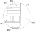
图6为图2中A处结构放大立体图;Figure 6 is an enlarged perspective view of the structure at A in Figure 2;
图7为图1中B处结构放大立体图;7 is an enlarged perspective view of the structure at B in FIG. 1;
图8为图1中C处结构放大立体图。FIG. 8 is an enlarged perspective view of the structure at C in FIG. 1 .
图中:In the picture:
1-第一聚水箱;2-开槽挡板;3-第一运水管道;401-装载筒;402-金属安装架;403-伺服电机;404-内接环;405-支撑杆;406-内胆;407-传动杆;408- 转盘;409-延伸杆;410-搅拌杆;411-安装环槽;412-加热棒;501-加压箱; 502-滑道;503-过滤板;504-衔接板;505-连接环;506-水泵;507-隔板;601- 第二聚水箱;602-顶盖;603-圆孔;604-喷枪;605-通水管;7-凹槽;8-金属杆;9-U型架;10-密封盖;11-第二运水道;12-第三运水道。1- The first water collecting tank; 2- Slotted baffle plate; 3- The first water pipe; 401- Loading cylinder; 402- Metal mounting bracket; 403- Servo motor; -Inner tank; 407-drive rod; 408-turntable; 409-extension rod; 410-stirring rod; 411-installation ring groove; 412-heating rod; 501-pressurized box; 502-slide; 504-connecting plate; 505-connecting ring; 506-water pump; 507-partition plate; 601-second collecting tank; 602-top cover; 603-round hole; 604-spray gun; 605-water pipe; 7-groove; 8-metal rod; 9-U-shaped frame; 10-sealing cover; 11-second waterway; 12-third waterway.
具体实施方式Detailed ways
下面结合附图并通过具体实施方式来进一步说明本发明的技术方案。The technical solutions of the present invention are further described below with reference to the accompanying drawings and through specific embodiments.
如图1-8所示,本发明提供一种技术方案:一种海绵城市系统,包括:第一聚水箱1,第一聚水箱1的顶部固定安装有开槽挡板2,开槽挡板2的外壁一侧分别设置有废渣处理机构、水流增压机构和地面供水机构。As shown in Figures 1-8, the present invention provides a technical solution: a sponge city system, comprising: a first
根据图1-4和图6-7所示,废渣供水机构包括装载筒401,装载筒401的内壁底部固定安装有金属安装架402,金属安装架402的内表壁固定插设有伺服电机403,第一聚水箱1的内表壁固定安装有三个内接环404,三个内接环404其中每个的内表壁均固定插设有一组支撑杆405,三组支撑杆405的外表壁之间固定套设有内胆406,伺服电机403的输出端固定安装有传动杆407,传动杆407 的顶部贯穿内胆406的底部,并位于内胆406的内部,传动杆407的外表壁固定套设有转盘408,转盘408的内部固定插设有多个延伸杆409,多个延伸杆409 其中每个的顶部均焊接有搅拌杆410,三个内接环404的内部均开设有一组安装环槽411,三组安装环槽411其中每三个的内表壁之间均固定安装有加热棒412,本系统设备采用分布对雨水处理的方式,将进入设备中混合水源进入高温的加热,提高细菌的分子活性,同时利用驱动部件加速分子结构的分解,使酸碱物质逐步降解,生成的残渣固体进行快速过滤,再储存到第二聚水箱601中供城市其他区域进行加湿,有效解决现有设备因只能进行水源的储存和后期对水源的倒运,而无法在雨水收集前进行灭菌处理的问题,避免储存的水源污染较大造成水源再次蒸发后形成污染性降水。As shown in FIGS. 1-4 and 6-7, the waste residue water supply mechanism includes a
根据图1-4所示,水流增压机构包括加压箱501,加压箱501的内壁两侧均固定安装有滑道502,两个滑道502的内表壁之间活动插设有过滤板503,加压箱501的内壁底部固定安装有衔接板504,衔接板504的内部固定安装有连接环 505连接环505的内表壁固定插设有水泵506,加压箱501的内壁两侧之间固定安装有隔板507,隔板507将加压箱501的内部分割成两个区域,水泵506的输出端贯穿隔板507的外壁一侧,并与其中一个区域相连通,加压箱501的外壁一侧固定连通有第二运水道11,水泵506的输出端固定连通有第三运水道12,通过设置水流增压机构,利用驱动部件产生的较强负压,快速将处理后的水源进行抽离,此过程中快速将掺杂在水源中的固体杂质进行剔除,避免固体杂质的不断堆积,造成管道间的堵塞,同时进一步提高处理后雨水的质量。As shown in FIGS. 1-4 , the water flow pressurization mechanism includes a
根据图1-5所示,供水机构包括第二聚水箱601,第二聚水箱601的顶部设置有顶盖602,顶盖602的顶部开设有多个圆孔603,多个圆孔603其中每个的直径数值均相等,多个圆孔603的内表壁均固定安装有喷枪604,多个喷枪604 其中每个的输入端均固定连通有通水管605,通过设置供水机构,可快速将储存的水源喷洒到使用区域中,提高设备整体的使用效率。1-5, the water supply mechanism includes a second
根据图1-4和图8所示,装载筒401的顶部开设有凹槽7,凹槽7的内壁两侧之间固定插设有金属杆8,金属杆8的外表壁活动套设有U型架9,U型架9 的外表壁固定安装有密封盖10,当需要对内胆406内的杂质进行清理时,利用金属杆8和U型架9之间的活动连接性,打开密封盖10即可。As shown in FIGS. 1-4 and 8 , a
根据图8所示,1-4的外壁一侧固定连通有第一运水管道3,第一运水管道 3的出水端贯穿装载筒401和内胆406的外表壁,并与内胆406的内部相连通,第二运水道11的进水端贯穿装载筒401和内胆406的外表壁,并与装载筒401 的内部相连通,第三运水道12的出水端和第二聚水箱601的外壁一侧相连通,通过第一运水管道3、第二运水道11和第三运水道12相互之间的连接关系,可有效将多个处理机构形成一个整体,提高设备对混合水源的净化效果。As shown in FIG. 8 , one side of the outer wall of 1-4 is fixedly connected with the first
其整个机构所达到的效果为:当每个机构部件根据使用功能的不同,分别埋入地层的不同深度,当降雨时,首先会下落至地表,并将杂质和细菌掺入到雨水中,从开槽挡板2的槽洞处初步储存在第一聚水箱1中,在水体积的压动下,混合水源利用第一运水管道3的运输进入到内胆406中,此时启动金属安装架402中的伺服电机403和加热棒412,随着时间的增加,加热棒412会持续释放热量,利用金属将的热传导,加热内胆406中混合水源,同时伺服电机403 在转动的过程中,带动传动杆407上的转盘408进行旋转,并使延伸杆409上的搅拌杆410不断对水源进行加速搅拌,当处理一段时间后,启动连接环505 中的水泵506,使加压箱501一半区域中负压不断增加,并作用于第二运水道 11,抽动内胆406中的液体,当水源进入到加压箱501中后,先由滑道502中的过滤板503进行过滤,再由第三运水道12的运输导入到第二聚水箱601中,当需要对第二聚水箱601顶部的地层进行加湿使,利用喷枪604中产生的吸附力,再通过通水管605的运输将第二聚水箱601中的水源移动至喷枪604中,经过喷枪604喷头处的压缩,喷附到地层内。The effect achieved by the whole mechanism is: when each mechanism component is buried in different depths of the stratum according to the different functions of use, when it rains, it will first fall to the surface, and the impurities and bacteria will be mixed into the rainwater. The slot hole of the slotted
本发明还提供了一种海绵城市系统的搭建方法,包括以下步骤:The present invention also provides a method for building a sponge city system, comprising the following steps:
步骤一:首先将第一聚水箱1、装载筒401、加压箱501和第二聚水箱601 埋入地层中,其中第一聚水箱1、装载筒401和第二聚水箱601的顶部裸露在地表上,并将第一聚水箱1顶部的开槽挡板2放置在雨水流动下游。Step 1: First, bury the first
步骤二:当雨水通过开槽挡板2上的槽洞,流入到第一聚水箱1中后,由于液体体积的增加,使得第一运水管道3中具备较高的压强,并冲击进内胆406 中,进入到内胆406中雨水掺杂有固体杂质及有害细菌,通过机构中的加热元件,提高有害细菌的分子活性,同时使强酸碱物质在高温的影响下快速分解,同时利用机构中的传动部件,对雨水进行搅拌,加速反应效率。Step 2: When the rainwater flows into the first
步骤三:当处理一段时间后,利用加压箱501中的水泵506增加一半区域中的负压,利用第二运水道11的运输先进入到加压箱501中,并对残渣进行过滤,并在少量液体回流下,通过第二运水道11再次进入到内胆406中,沉积在内胆406的底部Step 3: After processing for a period of time, use the
步骤四:当内胆406中沉积一定量的异物使,利用金属杆8和U型架9之间的活动连接性,打开装载筒401顶部的密封盖10,对内胆406内部的残渣进行清理即可。Step 4: When a certain amount of foreign matter is deposited in the
其整个一种海绵城市系统的搭建方法大致和上述一种海绵城市系统相同,其存在的主要区别在于,当处理后的雨水,在水泵506的抽动下,快速进入到第三运水道12中,由第三运水道12将雨水运输到第二聚水箱601中,因第二聚水箱601的顶部无限接近地表土壤,当该区域需要进行加湿时,圆孔603中的喷枪604其内部会产生较高的压缩能力,并由通水管605先将存储在第二聚水箱601的雨水导入进喷枪604内,再由喷枪604的喷头喷射到土壤中,在水源不断浸染下,使得该区域中快速保持湿润环境。The construction method of the entire sponge city system is roughly the same as that of the above-mentioned sponge city system. The main difference is that when the treated rainwater is pumped by the
本实施例的其它技术采用现有技术。Other technologies in this embodiment adopt existing technologies.
本发明是通过优选实施例进行描述的,本领域技术人员知悉,在不脱离本发明的精神和范围的情况下,可以对这些特征和实施例进行各种改变或等效替换。本发明不受此处所公开的具体实施例的限制,其他落入本申请的权利要求内的实施例都属于本发明保护的范围。The present invention has been described in terms of preferred embodiments, and those skilled in the art will appreciate that various changes or equivalent substitutions may be made to these features and embodiments without departing from the spirit and scope of the present invention. The present invention is not limited by the specific embodiments disclosed herein, and other embodiments falling within the claims of the present application all belong to the protection scope of the present invention.
Claims (10)
Priority Applications (1)
| Application Number | Priority Date | Filing Date | Title |
|---|---|---|---|
| CN202210359590.1A CN114892754A (en) | 2022-04-07 | 2022-04-07 | Sponge city system and building method thereof |
Applications Claiming Priority (1)
| Application Number | Priority Date | Filing Date | Title |
|---|---|---|---|
| CN202210359590.1A CN114892754A (en) | 2022-04-07 | 2022-04-07 | Sponge city system and building method thereof |
Publications (1)
| Publication Number | Publication Date |
|---|---|
| CN114892754A true CN114892754A (en) | 2022-08-12 |
Family
ID=82715705
Family Applications (1)
| Application Number | Title | Priority Date | Filing Date |
|---|---|---|---|
| CN202210359590.1A Pending CN114892754A (en) | 2022-04-07 | 2022-04-07 | Sponge city system and building method thereof |
Country Status (1)
| Country | Link |
|---|---|
| CN (1) | CN114892754A (en) |
Citations (6)
| Publication number | Priority date | Publication date | Assignee | Title |
|---|---|---|---|---|
| KR101037053B1 (en) * | 2010-09-10 | 2011-05-26 | 주식회사 수엔텍 | Non-point pollutant treatment device included in initial rainfall runoff |
| CN106277608A (en) * | 2016-08-31 | 2017-01-04 | 南宁丰优农业科技有限公司 | A kind of sewage-treatment plant with rainwater-collecting |
| CN106284484A (en) * | 2016-08-10 | 2017-01-04 | 江苏花王园艺股份有限公司 | Roof rain water garden special rainwater blood circulation |
| CN111760378A (en) * | 2020-06-29 | 2020-10-13 | 常州市市政工程设计研究院有限公司 | Sponge urban rainwater and sewage treatment system and technology thereof |
| CN213314529U (en) * | 2020-09-03 | 2021-06-01 | 山东格欣数控设备有限公司 | Dosing device for sewage treatment |
| CN214218454U (en) * | 2020-12-29 | 2021-09-17 | 江苏润泽水环境研究院有限公司 | Sponge urban rainwater processing apparatus |
-
2022
- 2022-04-07 CN CN202210359590.1A patent/CN114892754A/en active Pending
Patent Citations (6)
| Publication number | Priority date | Publication date | Assignee | Title |
|---|---|---|---|---|
| KR101037053B1 (en) * | 2010-09-10 | 2011-05-26 | 주식회사 수엔텍 | Non-point pollutant treatment device included in initial rainfall runoff |
| CN106284484A (en) * | 2016-08-10 | 2017-01-04 | 江苏花王园艺股份有限公司 | Roof rain water garden special rainwater blood circulation |
| CN106277608A (en) * | 2016-08-31 | 2017-01-04 | 南宁丰优农业科技有限公司 | A kind of sewage-treatment plant with rainwater-collecting |
| CN111760378A (en) * | 2020-06-29 | 2020-10-13 | 常州市市政工程设计研究院有限公司 | Sponge urban rainwater and sewage treatment system and technology thereof |
| CN213314529U (en) * | 2020-09-03 | 2021-06-01 | 山东格欣数控设备有限公司 | Dosing device for sewage treatment |
| CN214218454U (en) * | 2020-12-29 | 2021-09-17 | 江苏润泽水环境研究院有限公司 | Sponge urban rainwater processing apparatus |
Similar Documents
| Publication | Publication Date | Title |
|---|---|---|
| CN109914565B (en) | A kind of rotary cavernous body is synchronous to cut dirty and cleaning operation method | |
| CN110725578A (en) | Environment-friendly municipal complex of festival ground of collection sewage treatment plant and rubbish transfer station | |
| CN107215999A (en) | A kind of automatic collection and treatment device of river course oil slick | |
| CN103172223B (en) | Sewage treatment system and method for zero energy consumption land adsorbent bed | |
| CN207391119U (en) | The check dam of purifying river water | |
| CN205635178U (en) | Cascaded infiltration sewage treatment plant | |
| CN206070640U (en) | Gardens rainwater collection utilization unit | |
| CN111519745A (en) | A subsidence type green space rainwater collection device for sponge city construction | |
| CN215984191U (en) | Scale removing device for heat exchanger of central air-conditioning circulating system | |
| CN207130118U (en) | Packaged type sewage disposal system based on NW DMBR techniques | |
| CN214884192U (en) | Sponge urban water resource cyclic utilization system | |
| CN205253720U (en) | Engineering is with organic inorganic compound continuous prosthetic devices of tu shui integration that pollutes | |
| CN209507957U (en) | A kind of equipment of full-automatic biochemical processing lavatory excreta | |
| CN205556415U (en) | Novel treatment of domestic sewage master station | |
| CN212078822U (en) | Environment-friendly municipal complex of festival ground of collection sewage treatment plant and rubbish transfer station | |
| CN208378667U (en) | Efficient backwashing artificial ecological sewage land treatment system | |
| CN208033254U (en) | A kind of deep layer landfill gas vertical shaft device | |
| TWM547569U (en) | River ecological management system | |
| CN116857703B (en) | Energy configuration equipment for industrial park | |
| CN108640415B (en) | Efficient backwashing artificial ecological sewage land treatment system | |
| CN207958073U (en) | Waste incineration percolation liquid treating system | |
| CN204039148U (en) | Utilize movement process and the cyclic utilization system of forward osmosis membrane | |
| CN206256531U (en) | A kind of ecological shock resistance rainwater treatment reclamation set | |
| CN222346983U (en) | A multifunctional car washing machine | |
| CN217627848U (en) | Miniature sewage treatment drips irrigation device |
Legal Events
| Date | Code | Title | Description |
|---|---|---|---|
| PB01 | Publication | ||
| PB01 | Publication | ||
| SE01 | Entry into force of request for substantive examination | ||
| SE01 | Entry into force of request for substantive examination | ||
| RJ01 | Rejection of invention patent application after publication | ||
| RJ01 | Rejection of invention patent application after publication |
Application publication date: 20220812 |