CN114839047B - Withstand voltage detection device for civil engineering material experiments - Google Patents
Withstand voltage detection device for civil engineering material experiments Download PDFInfo
- Publication number
- CN114839047B CN114839047B CN202210776353.5A CN202210776353A CN114839047B CN 114839047 B CN114839047 B CN 114839047B CN 202210776353 A CN202210776353 A CN 202210776353A CN 114839047 B CN114839047 B CN 114839047B
- Authority
- CN
- China
- Prior art keywords
- plate
- detection
- box
- push rod
- transmission
- Prior art date
- Legal status (The legal status is an assumption and is not a legal conclusion. Google has not performed a legal analysis and makes no representation as to the accuracy of the status listed.)
- Active
Links
- 238000001514 detection method Methods 0.000 title claims abstract description 140
- 238000002474 experimental method Methods 0.000 title claims abstract description 18
- 239000000463 material Substances 0.000 title claims abstract description 17
- 238000001179 sorption measurement Methods 0.000 claims abstract description 46
- 230000005540 biological transmission Effects 0.000 claims abstract description 43
- 238000004140 cleaning Methods 0.000 claims abstract description 41
- 239000002893 slag Substances 0.000 claims abstract description 11
- 230000000007 visual effect Effects 0.000 claims abstract description 4
- 230000006835 compression Effects 0.000 claims description 16
- 238000007906 compression Methods 0.000 claims description 16
- 238000001125 extrusion Methods 0.000 claims description 11
- 239000000428 dust Substances 0.000 abstract description 20
- 238000012360 testing method Methods 0.000 description 40
- 239000012634 fragment Substances 0.000 description 26
- 230000000694 effects Effects 0.000 description 10
- 238000000034 method Methods 0.000 description 4
- 230000033001 locomotion Effects 0.000 description 3
- 238000003825 pressing Methods 0.000 description 2
- 238000007789 sealing Methods 0.000 description 2
- 235000008733 Citrus aurantifolia Nutrition 0.000 description 1
- 208000034656 Contusions Diseases 0.000 description 1
- 235000011941 Tilia x europaea Nutrition 0.000 description 1
- 238000010521 absorption reaction Methods 0.000 description 1
- 239000000654 additive Substances 0.000 description 1
- 230000001174 ascending effect Effects 0.000 description 1
- 230000009286 beneficial effect Effects 0.000 description 1
- 239000004568 cement Substances 0.000 description 1
- 238000005520 cutting process Methods 0.000 description 1
- 230000003028 elevating effect Effects 0.000 description 1
- 239000010881 fly ash Substances 0.000 description 1
- 230000005484 gravity Effects 0.000 description 1
- 239000004571 lime Substances 0.000 description 1
- 238000002156 mixing Methods 0.000 description 1
- 238000012986 modification Methods 0.000 description 1
- 230000004048 modification Effects 0.000 description 1
- 238000012856 packing Methods 0.000 description 1
- 239000002994 raw material Substances 0.000 description 1
- 238000005096 rolling process Methods 0.000 description 1
- 230000008054 signal transmission Effects 0.000 description 1
- 238000006467 substitution reaction Methods 0.000 description 1
- 238000010408 sweeping Methods 0.000 description 1
Images


Classifications
-
- G—PHYSICS
- G01—MEASURING; TESTING
- G01N—INVESTIGATING OR ANALYSING MATERIALS BY DETERMINING THEIR CHEMICAL OR PHYSICAL PROPERTIES
- G01N3/00—Investigating strength properties of solid materials by application of mechanical stress
- G01N3/02—Details
-
- B—PERFORMING OPERATIONS; TRANSPORTING
- B08—CLEANING
- B08B—CLEANING IN GENERAL; PREVENTION OF FOULING IN GENERAL
- B08B1/00—Cleaning by methods involving the use of tools
-
- B—PERFORMING OPERATIONS; TRANSPORTING
- B08—CLEANING
- B08B—CLEANING IN GENERAL; PREVENTION OF FOULING IN GENERAL
- B08B15/00—Preventing escape of dirt or fumes from the area where they are produced; Collecting or removing dirt or fumes from that area
- B08B15/04—Preventing escape of dirt or fumes from the area where they are produced; Collecting or removing dirt or fumes from that area from a small area, e.g. a tool
-
- G—PHYSICS
- G01—MEASURING; TESTING
- G01N—INVESTIGATING OR ANALYSING MATERIALS BY DETERMINING THEIR CHEMICAL OR PHYSICAL PROPERTIES
- G01N3/00—Investigating strength properties of solid materials by application of mechanical stress
- G01N3/08—Investigating strength properties of solid materials by application of mechanical stress by applying steady tensile or compressive forces
- G01N3/16—Investigating strength properties of solid materials by application of mechanical stress by applying steady tensile or compressive forces applied through gearing
-
- G—PHYSICS
- G01—MEASURING; TESTING
- G01N—INVESTIGATING OR ANALYSING MATERIALS BY DETERMINING THEIR CHEMICAL OR PHYSICAL PROPERTIES
- G01N2203/00—Investigating strength properties of solid materials by application of mechanical stress
- G01N2203/0001—Type of application of the stress
- G01N2203/0003—Steady
-
- G—PHYSICS
- G01—MEASURING; TESTING
- G01N—INVESTIGATING OR ANALYSING MATERIALS BY DETERMINING THEIR CHEMICAL OR PHYSICAL PROPERTIES
- G01N2203/00—Investigating strength properties of solid materials by application of mechanical stress
- G01N2203/0014—Type of force applied
- G01N2203/0016—Tensile or compressive
- G01N2203/0019—Compressive
-
- G—PHYSICS
- G01—MEASURING; TESTING
- G01N—INVESTIGATING OR ANALYSING MATERIALS BY DETERMINING THEIR CHEMICAL OR PHYSICAL PROPERTIES
- G01N2203/00—Investigating strength properties of solid materials by application of mechanical stress
- G01N2203/003—Generation of the force
- G01N2203/0032—Generation of the force using mechanical means
- G01N2203/0037—Generation of the force using mechanical means involving a rotating movement, e.g. gearing, cam, eccentric, or centrifuge effects
-
- G—PHYSICS
- G01—MEASURING; TESTING
- G01N—INVESTIGATING OR ANALYSING MATERIALS BY DETERMINING THEIR CHEMICAL OR PHYSICAL PROPERTIES
- G01N2203/00—Investigating strength properties of solid materials by application of mechanical stress
- G01N2203/003—Generation of the force
- G01N2203/005—Electromagnetic means
-
- Y—GENERAL TAGGING OF NEW TECHNOLOGICAL DEVELOPMENTS; GENERAL TAGGING OF CROSS-SECTIONAL TECHNOLOGIES SPANNING OVER SEVERAL SECTIONS OF THE IPC; TECHNICAL SUBJECTS COVERED BY FORMER USPC CROSS-REFERENCE ART COLLECTIONS [XRACs] AND DIGESTS
- Y02—TECHNOLOGIES OR APPLICATIONS FOR MITIGATION OR ADAPTATION AGAINST CLIMATE CHANGE
- Y02W—CLIMATE CHANGE MITIGATION TECHNOLOGIES RELATED TO WASTEWATER TREATMENT OR WASTE MANAGEMENT
- Y02W30/00—Technologies for solid waste management
- Y02W30/50—Reuse, recycling or recovery technologies
- Y02W30/91—Use of waste materials as fillers for mortars or concrete
Landscapes
- Physics & Mathematics (AREA)
- Health & Medical Sciences (AREA)
- Life Sciences & Earth Sciences (AREA)
- Chemical & Material Sciences (AREA)
- Analytical Chemistry (AREA)
- Biochemistry (AREA)
- General Health & Medical Sciences (AREA)
- General Physics & Mathematics (AREA)
- Immunology (AREA)
- Pathology (AREA)
- Force Measurement Appropriate To Specific Purposes (AREA)
Abstract
The invention belongs to the technical field of pressure resistance detection, and relates to a pressure resistance detection device for civil engineering material experiments, which comprises a detection box, a visual observation door hinged on the side wall of the detection box, a lifting plate and a bearing plate, wherein the bottom of the lifting plate is provided with a detection system, the top of the bearing plate is provided with two mounting plates arranged at intervals, a detection area is formed between the two mounting plates, one end of the detection area is provided with an auxiliary cleaning component for cleaning crushed slag, the bottom end inside the detection box is provided with a fixing plate which divides the detection box into a detection cavity and a transmission cavity, a driving component for driving the lifting plate to lift, an adsorption box and an exhaust box are arranged in the detection cavity, when the lifting plate is driven to lift by the driving component, the bearing plate is pushed to move upwards to be in an inclined state, the auxiliary cleaning component is matched to clean the crushed slag in the detection area in time, and the adsorption box and the exhaust box perform reciprocating air suction and exhaust, the dust is adsorbed and then stored, and the dust in the detection box is quickly cleaned.
Description
Technical Field
The invention relates to the technical field of pressure resistance detection, in particular to a pressure resistance detection device for civil engineering material experiments.
Background
The autoclaved aerated concrete block is a porous concrete product which is prepared by taking fly ash, lime, cement and the like as main raw materials, adding a proper amount of additives, and carrying out technical processes of material mixing, pouring, standing, cutting, high-pressure steam curing and the like.
When current survey compressive strength equipment was examining the building block, the building block can be by the crushing, leads to the concrete piece to splash, and current survey equipment can not effectively protect the operation workman, leads to the workman to be damaged by the concrete piece bruising easily, and the concrete piece is by the crushing back, and inconvenient sweeping, and the concrete that scatters influences operational environment.
The Chinese patent publication No. CN112179767A discloses an apparatus for measuring compressive strength of autoclaved aerated concrete blocks, which comprises a bottom plate, wherein symmetrical support plates are fixedly arranged on the upper side wall of the bottom plate, a first fixing plate is fixedly arranged on one side adjacent to the two support plates, a U-shaped frame is fixedly arranged on the lower side wall of the first fixing plate, a motor is fixedly arranged at the upper end of the first fixing plate, and a screw rod is longitudinally arranged in the U-shaped frame, so that when the detection apparatus presses and detects the blocks, the protection plates move to the upper end of a detection box, the blocks are effectively prevented from being crushed, the concrete blocks are prevented from splashing randomly to injure workers, accidents occur, the detection process is finished in the detection box, and the blocks are effectively prevented from being crushed, so that the concrete blocks are inconvenient to be cleaned and the determination work is influenced.
The above patents still have some disadvantages: 1. in the test block detection process, the concrete test block is crushed in the detection box when the pressure on the test block is too high, a fragment cleaning device is not arranged in the patent, the detection box needs to be opened during cleaning, then the next test block is manually detected after the fragment is cleaned, the reciprocating operation is very complicated, time and labor are wasted, and the concrete fragment on the top of the transverse plate is easily clamped in the sliding groove if the concrete fragment is not cleaned in time, so that the detection result of the next concrete test block is influenced; 2. when check out test set pressed the test block and examined time measuring, the broken a large amount of fragments and the dust of output of test block, the guard plate that this patent set up though the concrete splashes when can preventing that the building block from being crushed, but it can produce a large amount of dusts when broken and fly away out, influences the measuring environment in the work detection case.
Disclosure of Invention
The technical problem to be solved by the invention is as follows: in order to solve the problems that after the building blocks are crushed, concrete fragments are inconvenient to clean and easy to block, and a large amount of dust is generated to scatter out during crushing to influence the detection environment in a work detection box, the invention provides a pressure resistance detection device for civil engineering material experiments to solve the problems.
The invention provides a pressure resistance detection device for civil engineering material experiments, which comprises a detection box, a visible observation door hinged on the side wall of the detection box, a lifting plate and a bearing plate, wherein the bottom of the lifting plate is provided with a detection system, the top of the bearing plate is provided with two mounting plates arranged at intervals, a detection area is formed between the two mounting plates, one end of the detection area is provided with an auxiliary cleaning assembly for cleaning broken slag, the bottom end in the detection box is provided with a fixed plate which divides the detection box into a detection cavity and a transmission cavity, a driving assembly for driving the lifting plate to lift, an adsorption box and an exhaust box are arranged in the detection cavity, the adsorption box and the exhaust box are arranged diagonally, the adsorption box is positioned under one end of the lifting plate, the top end of the adsorption box is in transmission connection with the lifting plate, and the exhaust box is positioned right above the other end of the lifting plate, and the bottom of exhaust box with the lifter plate transmission is connected, be equipped with the drive assembly to the ascending lapse of loading board one end in the transmission intracavity, drive assembly is connected with the bottom transmission of adsorption tank, still set up the discharge gate that links up with the fixed plate upper surface on the lateral wall of detection case, the lifter plate sets up on drive assembly, the loading board is located the fixed plate directly over, and the bottom of loading board is connected with the drive assembly transmission, and the lifter plate moves down the time drive assembly and promotes the loading board and rotate in order to clear up the concrete fragment, and the dust of transmission adsorption tank and exhaust box simultaneous movement in to the air is clear away simultaneously, has also improved the clearance effect of residue when having improved the experimental work efficiency of concrete compressive strength.
Further, supplementary clearance subassembly includes the baffle, pushes away shovel, lead screw and scissor type expansion bracket, the baffle sets up at detection interval one end tip, it sets up in baffle one side to push away the shovel, the baffle outside is provided with first motor, the lead screw rotates and sets up inside the baffle, lead screw one end and first motor fixed connection, scissor type expansion bracket one end screw thread sets up on the lead screw, scissor type expansion bracket one end with push away shovel fixed connection, loading board one end tip is provided with first pressure sensitive sensor, the mounting panel lateral wall is kept away from baffle one end and is provided with second pressure sensitive sensor, first pressure sensitive sensor and second pressure sensitive sensor all with first motor signal connection, in time clear up the disintegrating slag on the detection interval, improve detection efficiency and testing result's accuracy.
Further, the symmetry is provided with a pair of anchor clamps on the detection interval, mounting panel one side is provided with electric putter, electric putter output and anchor clamps fixed connection, it has all seted up logical groove to push away the shovel both ends, it is provided with the clearance board to push away the shovel both ends, clearance board and logical groove sliding connection, it is provided with the extrusion spring to lead to the inslot, extrusion spring and clearance board fixed connection, it has the clearance brush to paste on the clearance board, the clearance brush is contradicted with anchor clamps, and the clearance board at its both ends is cleared up the anchor clamps in step when pushing away the shovel removal, and packing anchor clamps's normal detection is used, improves its life simultaneously.
Further, the interval lateral wall symmetry of detection is provided with a pair of spacing lug, push away shovel and spacing lug sliding connection, spacing lug section is the toper setting, the one end that fixed plate and discharge gate link up is the slope setting for it is spacing to push away the shovel, prevents to move on it and influences fragment clearance effect.
Further, the transmission assembly comprises a rotating plate, a long push rod, a short push rod and a universal ball bearing, wherein two ends of the rotating plate are rotatably connected with a rotating shaft, the rotating plate is rotatably connected with the inside of the detection box through the rotating shaft, two ends of the fixed plate are respectively provided with a sliding groove, one end of the fixed plate close to the adsorption box is provided with a through hole, the long push rod and the short push rod are respectively arranged in the two sliding grooves in a sliding manner, the tops of the long push rod and the short push rod are respectively and fixedly connected with a stop block, the universal ball bearing is fixedly arranged on the stop block, the long push rod and the short push rod are rotatably connected with the bearing plate through the universal ball bearing, the outer parts of the long push rod and the short push rod are respectively sleeved with a reset spring, the long push rod and the through hole are symmetrically arranged above the end part of the rotating plate, the bottom end of the short push rod is provided with a supporting plate, the supporting plate is fixedly connected with the inner wall of the detection box and is used for pushing one end of the bearing plate to move upwards, after the inclined plate is inclined, fragments above the inclined plate are discharged, and the effect of automatic cleaning is achieved.
Further, it is provided with the clamp plate to adsorb the case top, the intercommunication has the bellows between clamp plate and the adsorption box, clamp plate bottom fixedly connected with supports the feeler lever, support the feeler lever and run through the adsorption box, and with the sealed cooperation of adsorption box bottom axial sliding, support feeler lever and through-hole sliding connection, the outside cover of feeler lever is equipped with first compression spring, conflict respectively in the clamp plate bottom with adsorb the incasement in first compression spring both ends, first gas pocket has been seted up on the adsorption box lateral wall for the dust of raising up when clearing up the concrete test block is absorbed, thereby improves the inside measuring environment of detection case.
Further, it is provided with the movable plate to slide in the air discharge box, the movable plate bottom is provided with the pull rod, the pull rod runs through the air discharge box and extends to the lifter plate bottom, and with the sealed cooperation of air discharge box bottom axial, pull rod and lifter plate sliding connection, the outside cover of pull rod is equipped with second compression spring, second compression spring both ends are contradicted with movable plate and air discharge box respectively, air discharge box top symmetry is provided with two second gas pockets, and the cooperation adsorption box is further absorbed the dust that produces when breaking the concrete test block, further improves the inside measuring environment of detection case.
Further, drive assembly includes running gear, a pair of drive gear and a pair of screw rod, running gear rotates and sets up in detection case top intermediate position department, and the running gear top is provided with the second motor, and is a pair of the drive gear symmetry sets up in the running gear both sides, and with running gear meshes mutually, and is a pair of the screw rod symmetry sets up on the lifter plate, and with lifter plate threaded connection, and is a pair of the screw rod runs through the detection case, and with the detection case rotates to be connected, and is a pair of the screw rod respectively with a pair of drive gear fixed connection drives the lifter plate and reciprocates to accomplish and detect experiment work operation, improve detection efficiency.
The invention has the beneficial effects that:
firstly, the pressure-resistant detection device for civil engineering material experiments provided by the invention has the advantages that when the lifting plate moves downwards, the transmission assembly is matched to push one end of the bearing plate to move upwards, so that the bearing plate moves to an inclined state, fragments in a detection area are discharged along the inclined plane of the bearing plate, the fragments on the detection area can be timely cleaned, the automatic residue cleaning effect is realized, the bearing plate can be collided with the bearing plate when the fragments roll by matching with the arrangement of the extrusion spring, the bearing plate intermittently extrudes the extrusion spring, the bearing plate can continuously vibrate when the bearing plate inclines, the cleaning effect is improved, and compared with the prior art, the pressure-resistant detection device can effectively prevent the building blocks from being crushed, so that concrete blocks are inconvenient to clean and clean, and the detection work is influenced.
Secondly, according to the pressure-resistant detection device for the civil engineering material experiment, the auxiliary cleaning assembly is matched through the inclination angle of the bearing plate when the bearing plate is inclined, the broken slag remained in the detection area is further pushed out, meanwhile, the cleaning plates at the two ends of the pressure-resistant detection device clean the clamp when the push shovel reciprocates, and then the broken slag is cleaned in time, so that the normal detection and use of the clamp are guaranteed, the detection precision is improved, and the working efficiency of the concrete compressive strength test is greatly improved.
Thirdly, when the lifting plate is lifted, the adsorption boxes and the exhaust boxes at the two ends of the lifting plate are squeezed and pulled to perform reciprocating air suction and exhaust motion, the adsorbed dust scattered in the air is stored after being adsorbed, and the dust in the detection box is quickly cleaned, so that the detection environment in the detection box is improved, and the next concrete test block can be conveniently tested.
Drawings
In order to more clearly illustrate the embodiments of the present invention or the technical solutions in the prior art, the drawings used in the embodiments or the prior art descriptions will be briefly described below, and it is obvious that the drawings in the following description are some embodiments of the present invention, and other drawings can be obtained by those skilled in the art without creative efforts.
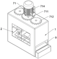
FIG. 1 is a schematic perspective view of a pressure-resistance detecting apparatus for civil engineering material experiments, according to the present invention,
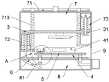
figure 2 is a plan sectional view of the detection box,
figure 3 is a schematic view of the operating state of the transmission assembly of the present invention,
figure 4 is an enlarged view of the structure at a of figure 2,
figure 5 is a schematic view of the working state of the auxiliary cleaning structure of the present invention,
figure 6 is a disassembled schematic view of the blade of the present invention,
figure 7 is a partial cross-sectional view of the test box of the present invention,
FIG. 8 is a schematic exploded view of the adsorption box of the present invention;
reference numerals: 1. a detection box; 2. a visual observation door; 3. a lifting plate; 31. a detection system; 4. a carrier plate; 41. mounting a plate; 42. an auxiliary cleaning assembly; 421. a baffle plate; 422. pushing and shoveling; 423. a screw rod; 424. a scissor-fork type telescopic frame; 425. a first motor; 426. a first pressure sensitive sensor; 427. a second pressure sensitive sensor; 5. detecting an interval; 51. a clamp; 52. an electric push rod; 53. a through groove; 54. cleaning the plate; 55. a compression spring; 56. a limiting bump; 6. a fixing plate; 61. a chute; 62. a through hole; 7. a detection chamber; 71. a drive assembly; 711. a rotating gear; 712. a transmission gear; 713. a screw; 714. a second motor; 72. an adsorption tank; 721. pressing a plate; 722. a bellows; 723. a touch bar; 724. a first compression spring; 725. a first air hole; 73. an exhaust box; 731. moving the plate; 732. a pull rod; 733. a second compression spring; 734. a second air hole; 8. a transmission cavity; 81. a transmission assembly; 811. a rotating plate; 812. a long push rod; 813. a short push rod; 814. a universal ball bearing; 815. a support plate; 816. a stopper; 817. a return spring; 9. and (4) a discharge port.
Detailed Description
The technical solutions of the present invention will be described clearly and completely with reference to the accompanying drawings, and it is to be understood that the described embodiments are only a part of the embodiments of the present invention, and not all of the embodiments.
In the embodiment, as shown in fig. 1 to 8, the pressure resistance detection device for civil engineering material experiments comprises a detection box 1 and a visual observation door 2 hinged on the side wall of the detection box 1, so as to observe and replace the detection state of a concrete test block at any time, and further comprises a lifting plate 3 and a bearing plate 4, wherein the bottom of the lifting plate 3 is provided with a detection system 31, the detection system 31 is a detection plate and a pressure sensor in the prior art and is used for testing the pressure resistance of the concrete test block, the top of the bearing plate 4 is provided with two mounting plates 41 arranged at intervals, a detection section 5 is formed between the two mounting plates 41, one end of the detection section 5 is provided with an auxiliary cleaning component 42 for cleaning broken slag, the detection section 5 is symmetrically provided with a pair of clamps 51, one side of the mounting plates 41 is provided with an electric push rod 52, the output end of the electric push rod 52 is fixedly connected with the clamps 51, when a concrete test block is tested, the concrete test block is placed in a detection area 5 on a bearing plate 4, then a pair of clamps 51 are driven by an electric push rod 52 to clamp and fix the concrete test block, the stability in the pressure resistance test process is ensured, the test data is prevented from deviation, then a driving assembly 71 drives a lifting plate 3 to move downwards, a detection system 31 moves downwards along with the concrete test block to carry out pressure resistance detection on the concrete test block, meanwhile, the concrete test block is detected in a detection box 1, the test block can be prevented from splashing around when the concrete test block is crushed, so that the safety is improved, a fixing plate 6 is arranged at the bottom end inside the detection box 1, the detection box 1 is divided into a detection cavity 7 and a transmission cavity 8 by the fixing plate 6, a driving assembly 71 for driving the lifting plate 3 to lift, an adsorption box 72 and an exhaust box 73 are arranged in the detection cavity 7, the adsorption box 72 and the exhaust box 73 are arranged diagonally, adsorption box 72 is located lifter plate 3 one end under, and adsorption box 72's top with lifter plate 3 transmission is connected, exhaust case 73 is located the lifter plate 3 other end directly over, and exhaust case 73's bottom with lifter plate 3 transmission is connected, be equipped with the drive assembly 81 of upwards advancing to loading board 4 one end in the transmission chamber 8, drive assembly 81 is connected with the bottom transmission of adsorption box 72, still set up the discharge gate 9 that links up with 6 upper surfaces of fixed plate on the lateral wall of detection case 1, lifter plate 3 sets up on drive assembly 71, loading board 4 is located fixed plate 6 directly over, and the bottom and the drive assembly 81 transmission of loading board 4 are connected.
Because the detection system 31 moves downwards, when the test block is extruded to perform pressure resistance detection, the extrusion force of the detection system is too large, so that the concrete test block is crushed on the detection section 5, at the moment, the lifting plate 3 continues to move downwards, the adsorption box 72 can be extruded and the exhaust box 73 can be pulled at the same time, so that the gas in the adsorption box is simultaneously discharged and adsorbed, the dust generated after the crushing is blown out and adsorbed, the adsorption box 72 is extruded and simultaneously transmitted with the transmission component 81, and one end of the bearing plate 4 is pushed to move upwards to an inclined state, the inclination angle of the bearing plate 4 is set to be 5-10 degrees, the inclination angle of the bearing plate cooperates with the auxiliary cleaning assembly 42 to push fragments out of the detection zone 5, the fragments in the detection zone 5 are conveyed to the discharge port 9 along the inclined plane of the fragments and conveyed to the collection box, the work efficiency of the concrete compressive strength test is greatly improved, and meanwhile the cleaning effect of residues on the detection zone 5 is also improved.
Because the bearing plate 4 is not inclined enough to completely remove fragment residues when concrete fragments are accumulated in the detection zone 5, an auxiliary cleaning assembly 42 is arranged at one end of the detection zone 5, the auxiliary cleaning assembly 42 comprises a baffle 421, a push shovel 422, a screw 423 and a scissor type telescopic frame 424, the baffle 421 is arranged at one end of the detection zone 5, the push shovel 422 is arranged at one side of the baffle 421, a first motor 425 is arranged outside the baffle 421, the screw 423 is rotatably arranged inside the baffle 421, one end of the screw 423 is fixedly connected with the first motor 425, one end of the scissor type telescopic frame 424 is arranged on the screw 423 in a threaded manner, one end of the scissor type telescopic frame 424 is fixedly connected with the push shovel 422, the scissor type telescopic frame 424 in the prior art is formed by hinging two support rods, and therefore, one end of the scissor type telescopic frame 424 in the embodiment is fixedly connected with the push shovel 422, one of the support rods at the other end is connected to the screw rod 423 in a threaded manner, the other support rod is fixed at the other end of the screw rod 423, so that the screw rod 423 drives one of the support rods to move when rotating, thereby enabling the scissor-fork type telescopic frame 424 to drive the push shovel 422 to freely extend and retract, the end part of one end of the bearing plate 4 is provided with a first pressure-sensitive sensor 426, the end of the side wall of the mounting plate 41, which is far away from the baffle 421, is provided with a second pressure-sensitive sensor 427, the first pressure-sensitive sensor 426 and the second pressure-sensitive sensor 427 are both in signal connection with a first motor 425, when the transmission component 81 pushes one end of the bearing plate 4 to move upwards, the first pressure-sensitive sensor 426 at the end part pushes against the side wall of the absorption box 72 when moving upwards, the first pressure-sensitive sensor 426 sends a signal to a processor outside the detection box 1, the processor starts the first motor 425 after receiving the signal, and the first motor 425 is a forward-reverse motor, first motor 425 drives lead screw 423 and rotates, make its scissor expansion bracket 424 promote to push away shovel 422 and remove and push away its fragment and residue to discharge gate 9, it is inconsistent with it when pushing away shovel 422 and removing to second pressure sensitive sensor 427, second pressure sensitive sensor 427 signal transmission arrives the treater, reverse first motor 425 after the treater received signal, make scissor expansion bracket 424 reset and drive its one end push away shovel 422 and reset in step, meanwhile, lifter plate 3 resets upward movement in step, drive its transmission assembly 81 and loading board 4 and reset in step and detect in order to carry out next concrete test block, can in time clear up the debris on the detection interval 5, and have the effect of automatic degree residue clearance, avoid influencing follow-up testing result, the clearance effect of concrete residue has been improved greatly when improving detection efficiency.
Because dust and slag generated during test block crushing can be attached to the clamp 51 to affect the clamping force of the clamp 51, through grooves 53 are formed in both ends of the push shovel 422, cleaning plates 54 are arranged at both ends of the push shovel 422, the cleaning plates 54 are slidably connected with the through grooves 53, an extrusion spring 55 is arranged in each through groove 53, the extrusion spring 55 is fixedly connected with the cleaning plate 54, a cleaning brush is adhered to each cleaning plate 54 and abutted against the clamp 51, when the push shovel 422 reciprocates, the cleaning plates 54 at both sides synchronously move, the cleaning brushes are adhered to the cleaning plates 54, when the test is finished, the electric push rod 52 drives the pair of clamps 51 to reset, and when the push shovel 422 moves to the clamping surface of the clamp 51 and abuts against the clamping surface, the cleaning plates 54 are extruded under the elastic force of the extrusion spring 55 to enable the brushes on the cleaning plates 54 to be tightly attached to the clamp 51 for cleaning, thereby clean dust and the residue of crushing adhesion on anchor clamps 51, can in time clear up the disintegrating slag, guaranteed anchor clamps 51's normal detection and use, also improved the precision that detects.
Because the push shovel 422 is easy to shift upwards when moving in the detection zone 5, thereby causing the residue to enter the bottom of the detection zone and affecting the cleaning effect, the side wall of the detection zone 5 is symmetrically provided with a pair of limiting lugs 56, the push shovel 422 is connected with the limiting lugs 56 in a sliding way, the section of the limiting lugs 56 is in a conical arrangement, the end of the fixed plate 6 connected with the discharge port 9 is in an inclined arrangement, at the moment, the push shovel 422 slides along the limiting lugs 56 on the two sides when moving, further, the push shovel 422 can be limited, the upward shift of the push shovel 422 when moving is avoided, thereby improving the stability, meanwhile, because the section of the limiting lugs 56 is in a conical arrangement, the crushed slag can be prevented from being blocked in the gap at the bottom of the limiting lugs 56, when the bearing plate 4 is inclined, the crushed block at the output end of the bearing plate can fall to the joint of the fixed plate 6 and the discharge port 9, therefore, the joint of the inclined plane is arranged to be connected with the discharge port 9, the fragments are prevented from being accumulated on the fixing plate 6 to influence the detection work.
Because the pressure of the detection system 31 is relatively high, in order to avoid damage caused by over-high pressure on the connection point when the bearing plate 4 is pushed to move upwards, the transmission assembly 81 comprises a rotating plate 811, a long push rod 812, a short push rod 813 and a universal ball bearing 814, wherein two ends of the rotating plate 811 are rotatably connected with rotating shafts, the rotating plate 811 is rotatably connected with the inside of the detection box 1 through the rotating shafts, so that one end of the highest point of the rotating plate 811 in an initial state is positioned under the adsorption box 72, two ends of the fixed plate 6 are both provided with sliding grooves 61, one end of the fixed plate 6 close to the adsorption box 72 is provided with a through hole 62, the long push rod 812 and the short push rod 813 are respectively slidably arranged in the two sliding grooves 61, the tops of the long push rod 812 and the short push rod 813 are both fixedly connected with a stopper 816, the universal ball bearing 814 is fixedly arranged on the stopper 816, and the long push rod 812 and the short push rod 813 are rotatably connected with the bearing plate 4 through the universal ball bearing 814, the long push rod 812 and the short push rod 813 are both externally sleeved with a return spring 817, the long push rod 812 and the through hole 62 are symmetrically arranged above the end portion of the rotating plate 811, the bottom end of the short push rod 813 is provided with a support plate 815, the support plate 815 is fixedly connected with the inner wall of the detection box 1, at this time, the bearing plate 4 is arranged above the fixing plate 6 in a horizontal state, a concrete test block is placed in the detection zone 5, the bearing plate 4 moves downwards due to the gravity of the concrete test block, and then the bearing plate presses downwards to cause the baffle 421 to synchronously move downwards in the chute 61, when the stopper 816 moves to the bottom of the chute 61, the bearing plate 4 abuts against the fixing plate 6, when the bearing plate 4 abuts against the fixing plate 6, the contact area can be increased, thereby avoiding that when the test block is detected, because the pressure of the detection system 31 is too large, the contact surface between the bearing plate 4 and the connection point between the long push rod 812 and the short push rod 813 is smaller to affect the detection result, meanwhile, the long push rod 812 and the short push rod 813 respectively abut against the end of the rotating plate 811 and the supporting plate 815, so that the stability is further improved, because the length of the long push rod 812 is inconsistent with that of the short push rod 813, and the long push rod 812 and the through hole 62 are symmetrically arranged above the end of the rotating plate 811, the lifting plate 3 is driven by the driving assembly 71 to press the adsorption box 72, so that the adsorption box 72 abuts against the rotating plate 811, the rotating plate 811 rotates along the rotating shaft, one end of the highest point of the rotating plate 811 rotates downwards under the action of force, one end of the lowest point rotates upwards, and further abuts against the long push rod 812 to move upwards along the sliding groove 61, so that the bearing plate 4 is pushed to rotate along the universal ball bearing 814 to form an inclined state, fragments are discharged along the inclined plane thereof in a sliding manner, so as to finish the fragment cleaning work, and when the fragments slide out, the fragments collide against the bearing plate 4 in a rolling manner by matching with the arrangement of the extrusion spring 55, the pressing spring 55 is intermittently pressed by the bearing plate 4, so that the bearing plate can intermittently generate vibration when being inclined, and the cleaning effect is improved.
Because the dust of the concrete fragments is continuously lifted and dispersed in the air when the concrete fragments are cleaned, and the detection environment inside the detection box is affected, a pressure plate 721 is arranged at the top end of the adsorption box 72, a corrugated pipe 722 is communicated between the pressure plate 721 and the adsorption box 72, a contact rod 723 is fixedly connected to the bottom of the pressure plate 721, the contact rod 723 penetrates through the adsorption box 72 and is in axial sliding sealing fit with the bottom of the adsorption box 72, the contact rod 723 is in sliding connection with the through hole 62, a first compression spring 724 is sleeved outside the contact rod 723, two ends of the first compression spring 724 respectively abut against the bottom of the pressure plate 721 and the inside of the adsorption box 72, a first air hole 725 is formed in the side wall of the adsorption box 72, when the lifting plate 3 moves downwards, the pressure plate 721 is forced to move downwards, the corrugated pipe 722 is compressed, the air inside is exhausted, and the contact rod 723 synchronously moves downwards to push the rotating plate 811 to be in transmission connection, after detection system 31 on lifter plate 3 detects and accomplishes, produce a large amount of dusts after its test block is broken, lifter plate 3 continues to move down this moment, until conflicting with adsorption box 72 top, and then the inside gas of adsorption box 72 continues to blow off, until inside gaseous whole discharge, blow the dust to exhaust box 73 bottom, when lifter plate 3 resets, first compression spring 724 elasticity shifts up its clamp plate 721, make its adsorption box 72 inside produce the negative pressure, the dust of raising when with the fragment roll-off absorbs, in order to reach and clear up the inside dust of detection box 1 fast, thereby improve detection box 1 internal environment, so that next concrete test block tests.
Meanwhile, the lifting plate 3 moves downwards and is connected with the exhaust box 73 in a transmission way, a moving plate 731 is arranged in the exhaust box 73 in a sliding way, a pull rod 732 is arranged at the bottom of the moving plate 731, the pull rod 732 penetrates through the exhaust box 73 to extend to the bottom of the lifting plate 3 and is in axial sealing fit with the bottom of the exhaust box 73, the pull rod 732 is connected with the lifting plate 3 in a sliding way, a second compression spring 733 is sleeved outside the pull rod 732, two ends of the second compression spring 733 are respectively abutted against the moving plate 731 and the exhaust box 73, two second air holes 734 are symmetrically arranged at the top of the exhaust box 73, when the adsorption box 72 blows dust to the bottom end of the exhaust box 73, the pull rod 732 at the bottom end of the exhaust box 73 pulls down the pull rod 732 and the moving plate 731 at the top end thereof when the lifting plate 3 moves downwards, and then external air and dust are sucked into the exhaust box 73 through the second air holes 734, so that the dust generated after the concrete block is crushed can be quickly absorbed, further, a duct and its valve are connected in the adsorption tank 72 and the exhaust tank 73 to facilitate cleaning of dust collected therein, which is prior art and thus not illustrated in the drawings.
The driving assembly 71 includes a rotation gear 711, a pair of transmission gears 712 and a pair of screws 713, the rotating gear 711 is rotatably arranged at the middle position of the top of the detection box 1, the second motor 714 is arranged at the top of the rotating gear 711, a pair of the transmission gears 712 are symmetrically arranged at two sides of the rotating gear 711, and is engaged with the rotating gear 711, a pair of the screws 713 are symmetrically provided on the elevating plate 3, and is connected with the lifting plate 3 by screw thread, a pair of the screw rods 713 penetrates through the detection box 1 and is connected with the detection box 1 in a rotating way, the pair of the screw rods 713 are respectively and fixedly connected with a pair of the transmission gears 712, when in detection, the second motor 714 is driven to drive the rotating gear 711 to rotate, so that the meshed transmission gears 712 at the two ends of the second motor rotate to drive the pair of screw rods 713 to rotate, and the lifting plate 3 is driven to move up and down, so as to complete the detection experiment.
Finally, it should be noted that: the above embodiments are only used to illustrate the technical solution of the present invention, and not to limit the same; while the invention has been described in detail and with reference to the foregoing embodiments, it will be understood by those skilled in the art that: the technical solutions described in the foregoing embodiments may still be modified, or some or all of the technical features may be equivalently replaced; and the modifications or the substitutions do not make the essence of the corresponding technical solutions depart from the scope of the technical solutions of the embodiments of the present invention.
Claims (6)
1. The utility model provides a withstand voltage detection device for civil engineering material experiments, includes detection case (1) and articulates visual observation door (2) on detection case (1) lateral wall, its characterized in that still includes lifter plate (3) and loading board (4), lifter plate (3) bottom is provided with detecting system (31), loading board (4) top is equipped with mounting panel (41) that two intervals set up, has formed between two mounting panels (41) and has detected interval (5), the one end that detects interval (5) is equipped with carries out supplementary clearance subassembly (42) of clearing up the disintegrating slag, the inside bottom of detection case (1) is provided with fixed plate (6), fixed plate (6) divide into detection chamber (7) and transmission chamber (8) with detection case (1), be equipped with in detection chamber (7) and be used for driving drive assembly (71) that lifter plate (3) go up and down, Adsorption box (72) and exhaust box (73), adsorption box (72) and exhaust box (73) are diagonal angle setting, adsorption box (72) is located lifter plate (3) one end under, and the top of adsorption box (72) is connected with lifter plate (3) transmission, exhaust box (73) is located lifter plate (3) other end directly over, and the bottom of exhaust box (73) with lifter plate (3) transmission is connected, be equipped with transmission assembly (81) to the one end of loading board (4) lapse upwards in transmission chamber (8), transmission assembly (81) and the bottom transmission of adsorption box (72) are connected, still set up discharge gate (9) that link up with fixed plate (6) upper surface on the lateral wall of detection case (1), lifter plate (3) sets up on drive assembly (71), loading board (4) are located fixed plate (6) directly over, the bottom end of the bearing plate (4) is in transmission connection with a transmission assembly (81), the auxiliary cleaning assembly (42) comprises a baffle plate (421), a push shovel (422), a screw rod (423) and a scissor type expansion bracket (424), the baffle plate (421) is arranged at one end of a detection area (5), the push shovel (422) is arranged on one side of the baffle plate (421), a first motor (425) is arranged outside the baffle plate (421), the screw rod (423) is rotatably arranged inside the baffle plate (421), one end of the screw rod (423) is fixedly connected with the first motor (425), one end of the scissor type expansion bracket (424) is arranged on the screw rod (423) in a threaded manner, one end of the scissor type expansion bracket (424) is fixedly connected with the push shovel (422), a first pressure-sensitive sensor (426) is arranged at one end of the bearing plate (4), a second pressure-sensitive sensor (427) is arranged at one end, far away from the baffle plate (421), of the side wall of the mounting plate (41), the first pressure-sensitive sensor (426) and the second pressure-sensitive sensor (427) are in signal connection with a first motor (425), the transmission assembly (81) comprises a rotating plate (811), a long push rod (812), a short push rod (813) and a universal ball bearing (814), two ends of the rotating plate (811) are rotatably connected with a rotating shaft, the rotating plate (811) is rotatably connected with the inside of the detection box (1) through the rotating shaft, two ends of the fixing plate (6) are respectively provided with a sliding groove (61), one end, close to the adsorption box (72), of the fixing plate (6) is provided with a through hole (62), the long push rod (812) and the short push rod (813) are respectively arranged in the two sliding grooves (61) in a sliding manner, the tops of the long push rod (812) and the short push rod (813) are respectively and fixedly connected with a stop block (816), the universal ball bearing (814) is fixedly arranged on the stop block (816), and the long push rod (812) and the short push rod (813) are rotatably connected with the bearing plate (4) through the universal ball bearing (814), the outer portions of the long push rod (812) and the short push rod (813) are respectively sleeved with a return spring (817), the long push rod (812) and the through hole (62) are symmetrically arranged above the end portion of the rotating plate (811), a supporting plate (815) is arranged at the bottom end of the short push rod (813), and the supporting plate (815) is fixedly connected with the inner wall of the detection box (1).
2. The pressure-resistance detecting device for civil engineering material experiments as described in claim 1, wherein: the symmetry is provided with a pair of anchor clamps (51) on detection interval (5), mounting panel (41) one side is provided with electric putter (52), electric putter (52) output and anchor clamps (51) fixed connection, it all has seted up logical groove (53) to push away shovel (422) both ends, it is provided with cleaning plate (54) to push away shovel (422) both ends, cleaning plate (54) and logical groove (53) sliding connection, be provided with extrusion spring (55) in logical groove (53), extrusion spring (55) and cleaning plate (54) fixed connection, it has the clearance brush to paste on cleaning plate (54), the clearance brush is contradicted with anchor clamps (51).
3. The pressure-resistance detecting device for civil engineering material experiments as described in claim 2, wherein: the lateral wall symmetry of detection interval (5) is provided with a pair of spacing lug (56), push away shovel (422) and spacing lug (56) sliding connection, spacing lug (56) section is the toper setting, the one end that fixed plate (6) and discharge gate (9) link up sets up for the slope.
4. The pressure-resistance detecting device for civil engineering material experiments as described in claim 1, wherein: adsorb case (72) top and be provided with clamp plate (721), the intercommunication has bellows (722) between clamp plate (721) and adsorb case (72), clamp plate (721) bottom fixedly connected with supports feeler lever (723), support feeler lever (723) and run through adsorb case (72), and with adsorb case (72) bottom axial sliding seal cooperation, support feeler lever (723) and through-hole (62) sliding connection, it is equipped with first compression spring (724) to support feeler lever (723) outside cover, contradict respectively in clamp plate (721) bottom and adsorb case (72) first compression spring (724) both ends, first gas pocket (725) has been seted up on adsorbing case (72) lateral wall.
5. The pressure-resistance detecting device for civil engineering material experiments as described in claim 1, wherein: slide in exhaust case (73) and be provided with movable plate (731), movable plate (731) bottom is provided with pull rod (732), pull rod (732) run through exhaust case (73) and extend to lifter plate (3) bottom, and with exhaust case (73) bottom axial seal cooperation, pull rod (732) and lifter plate (3) sliding connection, the outside cover of pull rod (732) is equipped with second compression spring (733), second compression spring (733) both ends are contradicted with movable plate (731) and exhaust case (73) respectively, exhaust case (73) top symmetry is provided with two second gas holes (734).
6. The pressure-resistance detecting device for civil engineering material experiments as described in claim 1, wherein: the driving assembly (71) comprises a rotating gear (711), a pair of transmission gears (712) and a pair of screws (713), the rotating gear (711) is rotatably arranged at the middle position of the top of the detection box (1), a second motor (714) is arranged at the top of the rotating gear (711), the pair of transmission gears (712) are symmetrically arranged on two sides of the rotating gear (711) and are meshed with the rotating gear (711), the pair of screws (713) are symmetrically arranged on the lifting plate (3) and are in threaded connection with the lifting plate (3), the pair of screws (713) penetrate through the detection box (1) and are rotatably connected with the detection box (1), and the pair of screws (713) are respectively and fixedly connected with the pair of transmission gears (712).
Priority Applications (1)
| Application Number | Priority Date | Filing Date | Title |
|---|---|---|---|
| CN202210776353.5A CN114839047B (en) | 2022-07-04 | 2022-07-04 | Withstand voltage detection device for civil engineering material experiments |
Applications Claiming Priority (1)
| Application Number | Priority Date | Filing Date | Title |
|---|---|---|---|
| CN202210776353.5A CN114839047B (en) | 2022-07-04 | 2022-07-04 | Withstand voltage detection device for civil engineering material experiments |
Publications (2)
| Publication Number | Publication Date |
|---|---|
| CN114839047A CN114839047A (en) | 2022-08-02 |
| CN114839047B true CN114839047B (en) | 2022-09-09 |
Family
ID=82573584
Family Applications (1)
| Application Number | Title | Priority Date | Filing Date |
|---|---|---|---|
| CN202210776353.5A Active CN114839047B (en) | 2022-07-04 | 2022-07-04 | Withstand voltage detection device for civil engineering material experiments |
Country Status (1)
| Country | Link |
|---|---|
| CN (1) | CN114839047B (en) |
Families Citing this family (7)
| Publication number | Priority date | Publication date | Assignee | Title |
|---|---|---|---|---|
| CN115876566B (en) * | 2022-11-24 | 2024-05-24 | 嘉兴市中元德丰建材股份有限公司 | High-efficiency detection device and detection method for compressive strength of concrete product |
| CN116296845B (en) * | 2023-03-07 | 2026-04-24 | 重庆大学 | A prefabricated retaining wall strength testing device |
| CN116256233B (en) * | 2023-05-16 | 2023-07-18 | 苏州新地建设工程质量检测有限公司 | Building cement quality detection device |
| CN117491374B (en) * | 2023-12-29 | 2024-03-08 | 常州纺兴精密机械有限公司 | Device and method for detecting holes and holes of spinneret plate of island-type composite component |
| CN117990332B (en) * | 2024-04-03 | 2024-05-31 | 哈尔滨学院 | Computer detection equipment |
| CN119688463A (en) * | 2024-12-17 | 2025-03-25 | 怒江州质量技术监督综合检测中心 | Concrete tile bearing capacity test detection device |
| CN120213643B (en) * | 2025-05-22 | 2025-09-02 | 锐城(天津)建筑工程质量检验检测有限公司 | A device for testing the compressive strength of material test blocks |
Family Cites Families (8)
| Publication number | Priority date | Publication date | Assignee | Title |
|---|---|---|---|---|
| CN210166223U (en) * | 2019-04-18 | 2020-03-20 | 天津远大兴辰住宅工业有限公司 | Pressure testing machine convenient to clearance |
| CN111208011B (en) * | 2020-02-26 | 2021-07-02 | 济南城隆建材有限公司 | A kind of coal fly ash autoclaved aerated concrete block strength testing device |
| WO2021189172A1 (en) * | 2020-03-22 | 2021-09-30 | 苏州昇特智能科技有限公司 | Dust removal and cleaning device for testing planar flexible materials |
| CN112268802A (en) * | 2020-10-27 | 2021-01-26 | 王东海 | Concrete quality safety inspection device for housing construction |
| CN214584536U (en) * | 2021-04-13 | 2021-11-02 | 齐浩 | Concrete quality safety inspection device for housing construction |
| CN113029801B (en) * | 2021-04-16 | 2024-07-23 | 湖州纬达建材科技有限公司 | Pressure-resistant detection equipment for preventing scraps from splashing for aerated concrete blocks |
| CN215296912U (en) * | 2021-06-17 | 2021-12-24 | 四川迈瑞特新型建材科技有限责任公司 | A detection device for the production of aerated blocks |
| CN215812017U (en) * | 2021-07-09 | 2022-02-11 | 湖州汇能新材料科技有限公司 | Evaporate and press aerated concrete block detection device |
-
2022
- 2022-07-04 CN CN202210776353.5A patent/CN114839047B/en active Active
Also Published As
| Publication number | Publication date |
|---|---|
| CN114839047A (en) | 2022-08-02 |
Similar Documents
| Publication | Publication Date | Title |
|---|---|---|
| CN114839047A (en) | Withstand voltage detection device for civil engineering material experiments | |
| CN113376023A (en) | Test block protection cleaning method for concrete compressive strength detection test | |
| CN111811952B (en) | Bearing capacity detection device for building detection | |
| CN116773353A (en) | Concrete product production compressive strength detection device | |
| CN211386241U (en) | A sheet metal waste collection device for a cutting machine | |
| CN215115691U (en) | A kind of building material hardness testing device | |
| CN221280772U (en) | Concrete pressure testing machine | |
| CN217585746U (en) | Carbonization depth tester for detecting carbonization depth of construction steel bar | |
| CN114778314B (en) | Construct special brick intensity quality detection device | |
| CN214539018U (en) | Building materials pressure test instrument comprehensive detector | |
| CN220568529U (en) | A new type of material strength detection device | |
| CN206515155U (en) | Pavement material intensity measuring instrument | |
| CN210953608U (en) | Electro-hydraulic pressure testing machine | |
| CN210533881U (en) | Universal material testing machine capable of automatically collecting slag | |
| CN114778292A (en) | Hydraulic engineering concrete strength detection device and use method | |
| CN210969443U (en) | Drilling machine for building detection | |
| CN213516602U (en) | Anti-cracking mortar strength detection device | |
| CN207779808U (en) | A kind of strength-testing machine easy to use | |
| CN217180355U (en) | Concrete compressive strength detection device for civil engineering | |
| CN218330904U (en) | Construction engineering is intensity detection device for concrete slab | |
| CN219224363U (en) | Pressure testing machine | |
| CN218098678U (en) | A testing machine for compressive strength of construction engineering materials | |
| CN222439279U (en) | A building material strength testing device | |
| CN213456417U (en) | Pressure testing machine convenient to clearance | |
| CN218222587U (en) | Press for detecting building main body structure |
Legal Events
| Date | Code | Title | Description |
|---|---|---|---|
| PB01 | Publication | ||
| PB01 | Publication | ||
| SE01 | Entry into force of request for substantive examination | ||
| SE01 | Entry into force of request for substantive examination | ||
| GR01 | Patent grant | ||
| GR01 | Patent grant | ||
| PE01 | Entry into force of the registration of the contract for pledge of patent right |
Denomination of invention: Pressure resistance testing device for civil engineering material experiments Effective date of registration: 20231201 Granted publication date: 20220909 Pledgee: Yantai financing guarantee Group Co.,Ltd. Pledgor: Yantai Hua Hong Building Technology Co.,Ltd. Registration number: Y2023980068860 |
|
| PE01 | Entry into force of the registration of the contract for pledge of patent right |