Disclosure of Invention
The invention aims to provide a fermentation tank, which aims to solve the technical problems that the internal temperature is increased by a heating mode of arranging a heating pipe on the outer wall of a tank body for heating in the prior art, but the internal temperature of the tank body is easily uneven, the temperature of a part close to the heating pipe is higher than that of a part far away from the heating pipe, the heating is uneven, the temperature control is uneven, and the fermentation effect is influenced.
In order to achieve the purpose, the fermentation tank adopted by the invention comprises a tank body, a tank cover, a stirring assembly and a temperature control assembly, wherein the tank cover is detachably connected with the tank cover and is positioned on one side of the tank cover, and the stirring assembly is connected with the tank cover;
the temperature control component comprises a stirring rod, a heating wire, a temperature control cover, a heating component and a cooling component, the stirring rod is connected with the stirring component, the heating wire is located in the stirring rod, the temperature control cover is fixedly connected with the tank body and located in the outer side of the tank body, the tank body forms an accommodating space, the heating component is communicated with the accommodating space, and the cooling component is connected with the temperature control cover.
The heating component comprises a heating box, a heating rod and a fan, wherein the heating box is positioned on the outer side of the tank body and is communicated with the accommodating space through a guide pipe; the heating rod is fixedly connected with the heating box and is positioned in the heating box; the fan with heating cabinet fixed connection to the output with the inside intercommunication of heating cabinet.
The heating component also comprises an air outlet pipe and a valve, and the air outlet pipe is communicated with the temperature control cover and is positioned on one side of the temperature control cover, which is far away from the heating box; the valve is connected with the air outlet pipe.
The stirring assembly comprises a driving motor, a rotating shaft, a stirring blade and an auxiliary component, and the driving motor is positioned above the tank cover; the rotating shaft is fixedly connected with the output end of the driving motor and extends into the tank body; the stirring blade is fixedly connected with the rotating shaft and is positioned in the tank body; the rotating shaft is connected with the stirring rod; the auxiliary member is connected to the rotating shaft.
The auxiliary component comprises a connecting rod, a brush and a connecting part, wherein the connecting rod is fixedly connected with the rotating shaft and is positioned on one side of the rotating shaft, which is far away from the stirring blade; the brush is fixedly connected with the connecting rod and is positioned on one side of the connecting rod, which is far away from the rotating shaft; the connecting part is connected with the connecting rod.
The stirring assembly further comprises a threaded rod, and the threaded rod is fixedly connected with the rotating shaft and is located at the bottom end of the rotating shaft.
The fermentation tank also comprises a discharge pipe and a control valve, wherein the discharge pipe is communicated with the tank body and is positioned on one side of the tank body, which is far away from the tank cover; the control valve is connected with the discharge pipe.
According to the fermentation tank, the tank body is closed through the tank cover, the stirring component is used for stirring in the tank body to assist fermentation, the stirring rod is connected with the stirring component and rotates along with the stirring component, the electric heating wire is arranged on the inner wall of the stirring rod, the stirring rod is heated when the power supply is switched on to operate, the heated stirring rod rotates in the tank body, fermented materials in the tank body are heated uniformly, the temperature control cover is arranged on the outer wall of the tank body, the temperature rising component raises the temperature of the tank body, and the temperature lowering component lowers the temperature of the tank body, so that temperature regulation is realized, fermentation is facilitated, the temperature is further heated uniformly, and the fermentation effect is improved.
Drawings
In order to more clearly illustrate the embodiments of the present invention or the technical solutions in the prior art, the drawings used in the description of the embodiments or the prior art will be briefly described below, it is obvious that the drawings in the following description are only some embodiments of the present invention, and for those skilled in the art, other drawings can be obtained according to the drawings without creative efforts.
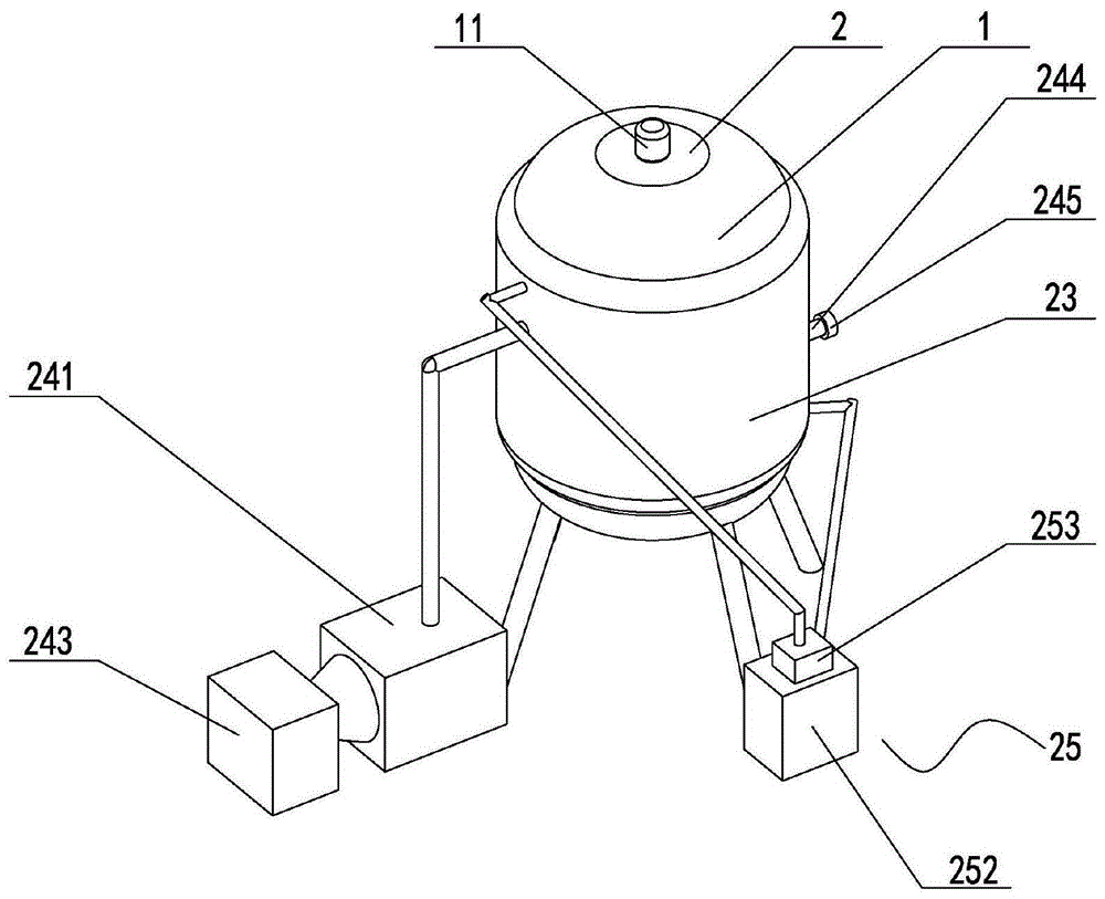
FIG. 1 is a schematic view of the structure of a fermenter according to the present invention.
FIG. 2 is a front view of a fermenter according to the present invention.
FIG. 3 is a sectional view of a fermenter according to the present invention.
Fig. 4 is a schematic structural view of the stirring assembly of the present invention.
Fig. 5 is an enlarged view of fig. 4 at a of the present invention.
1-tank body, 2-tank cover, 3-discharge pipe, 4-control valve, 10-stirring component, 11-driving motor, 12-rotating shaft, 13-stirring blade, 14-auxiliary component, 15-threaded rod, 20-temperature control component, 21-stirring rod, 22-heating wire, 23-temperature control cover, 24-heating component, 25-cooling component, 141-connecting rod, 142-hairbrush, 143-connecting component, 231-containing space, 241-heating box, 242-heating rod, 243-fan, 244-air outlet pipe, 245-valve, 251-circulating pipe, 252-water tank, 253-water pump, 1431-mounting seat and 1432-ball.
Detailed Description
Reference will now be made in detail to embodiments of the present invention, examples of which are illustrated in the accompanying drawings, wherein like or similar reference numerals refer to the same or similar elements or elements having the same or similar function throughout. The embodiments described below with reference to the drawings are illustrative and intended to be illustrative of the invention and are not to be construed as limiting the invention.
In the description of the present invention, it is to be understood that the terms "length", "width", "upper", "lower", "front", "rear", "left", "right", "vertical", "horizontal", "top", "bottom", "inner", "outer", and the like, indicate orientations or positional relationships based on the orientations or positional relationships illustrated in the drawings, and are used merely for convenience in describing the present invention and for simplicity in description, and do not indicate or imply that the devices or elements referred to must have a particular orientation, be constructed in a particular orientation, and be operated, and thus, are not to be construed as limiting the present invention. Further, in the description of the present invention, "a plurality" means two or more unless specifically defined otherwise.
Referring to fig. 1, 2, 3 and 5, the present invention provides a fermentation tank, which comprises a tank body 1, a tank cover 2, a stirring assembly 10 and a temperature control assembly 20, wherein the tank cover 2 is detachably connected to the tank cover and is located at one side of the tank cover, and the stirring assembly 10 is connected to the tank cover 2;
temperature control assembly 20 includes puddler 21, heating wire 22, control by temperature change cover 23, intensification component 24 and cooling component 25, puddler 21 with stirring assembly 10 is connected, heating wire 22 is located the inside of puddler 21, control by temperature change cover 23 with jar body 1 fixed connection, and be located the outside of jar body 1, and with jar body 1 forms accommodation space 231, intensification component 24 with accommodation space 231 communicates, cooling component 25 with control by temperature change cover 23 is connected.
Further, referring to fig. 3, the fermentation tank further includes a discharge pipe 3 and a control valve 4, the discharge pipe 3 is communicated with the tank body 1 and is located on a side of the tank body 1 away from the tank cover 2; the control valve 4 is connected to the tapping pipe 3.
In this embodiment, the tank cover 2 closes the tank body 1, the stirring assembly 10 stirs the materials inside the tank body 1 to assist fermentation, the stirring rod 21 is connected with the stirring assembly 10 and connected with the stirring assembly 10, the heating wire is arranged inside the stirring rod 21, the power is turned on to generate heat, the stirring rod 21 generates heat, the stirring rod 21 heats the materials inside the tank body 1 while stirring, the heating is uniform, the fermentation effect is improved, the temperature control cover 23 is arranged outside the tank body 1, the temperature raising framework heats the tank body 1, the temperature lowering component 25 lowers the temperature of the tank body 1, the temperature is controllable, the fermentation effect is ensured, the discharging pipe 3 is arranged at the bottom of the tank body 1 and is used for discharging the fermented materials, the control valve 4 is JD745X, the setting is in on discharging pipe 3, the discharge of control material, and then effectively carry out the even heating to the material to the temperature is controllable, makes the fermentation effect better.
Further, referring to fig. 1, 2 and 3, the warming member 24 includes a heating box 241, a heating rod 242 and a blower 243, the heating box 241 is located outside the tank 1 and is communicated with the accommodating space 231 through a conduit; the heating rod 242 is fixedly connected with the heating box 241 and is positioned inside the heating box 241; the fan 243 is fixedly connected with the heating box 241, and the output end of the fan is communicated with the inside of the heating box 241.
Further, referring to fig. 1 and fig. 2, the temperature raising member 24 further includes an air outlet pipe 244 and a valve 245, the air outlet pipe 244 is communicated with the temperature control cover 23 and is located on a side of the temperature control cover 23 away from the heating box 241; the valve 245 is connected with the air outlet pipe 244.
Further, referring to fig. 1, 2, 3 and 5, the cooling member 25 includes a circulation pipe 251, a water tank 252 and a water pump 253, the circulation pipe 251 is connected to the temperature control cover 23 and is located in the accommodating space 231; the water tank 252 is positioned outside the tank body 1; the water pump 253 is respectively communicated with the circulation pipe 251 and the water tank 252 through pipes.
In this embodiment, the heating box 241 is located outside the tank body 1, the heating rod 242 is arranged inside the heating box 241, the type of the heating rod 242 is DHF4.5, and heats the air in the heating box 241, the type of the fan 243 is W2E200, and is communicated with the inside of the heating box 241, so that the air is supplied into the heating box 241 and then passes through the heating rod 242 to be heated, the hot air is conveyed into the accommodating space 231 between the temperature control cover 23 and the tank body 1 through a conduit and then is discharged from the air outlet pipe 244, the type of the valve 245 is WCB20 and is arranged on the air outlet pipe 244 to control the discharge of the hot air, so far, when the temperature of the inside of the tank body 1 needs to be raised, the fan 243 is controlled to be started, so that the air is supplied into the heating box 241 and passes through the heating rod 242 to be heated to generate the hot air, and then the hot air is sent into the accommodating space 231 through the conduit, the heat is transferred to the inside of the tank body 1 through heat transfer, the heating wire 22 is assisted to heat the materials, the fermentation effect is guaranteed, and the hot gas is finally discharged through the air outlet pipe 244; the circulating pipe 251 is spirally wound on the outer side of the tank body 1 and is located in the accommodating space 231, the cooling liquid is filled in the water tank 252, the water pump 253 is of a CPS600 type and is communicated with the water tank 252 and the circulating pipe 251 through a conduit, so that when the tank body 1 needs to be cooled, the heating wire 22 is closed, the cooling liquid in the water tank 252 is pumped into the circulating pipe 251 by the water pump 253, high temperature is taken away after the cooling liquid circulates in the circulating pipe 251, the cooling liquid is circulated back to the water tank 252 for cyclic utilization, the temperature of the tank body 1 can be cooled and raised, temperature control is achieved, and the fermentation effect is guaranteed.
Further, referring to fig. 1, 3 and 4, the stirring assembly 10 includes a driving motor 11, a rotating shaft 12, a stirring blade 13 and an auxiliary member 14, wherein the driving motor 11 is located above the can lid 2; the rotating shaft 12 is fixedly connected with the output end of the driving motor 11 and extends into the tank body 1; the stirring blade 13 is fixedly connected with the rotating shaft 12 and is positioned in the tank body 1; the rotating shaft 12 is connected with the stirring rod 21; the auxiliary member 14 is connected to the rotating shaft 12.
Further, referring to fig. 3, 4 and 5, the auxiliary member 14 includes a connecting rod 141, a brush 142 and a connecting part 143, wherein the connecting rod 141 is fixedly connected to the rotating shaft 12 and is located on a side of the rotating shaft 12 away from the stirring vane 13; the brush 142 is fixedly connected with the connecting rod 141 and is positioned on one side of the connecting rod 141 away from the rotating shaft 12; the connection member 143 is connected to the connection rod 141.
Further, referring to fig. 3, the stirring assembly 10 further includes a threaded rod 15, and the threaded rod 15 is fixedly connected to the rotating shaft 12 and is located at the bottom end of the rotating shaft 12.
Further, referring to fig. 5, the connecting part 143 includes a mounting seat 1431 and a ball 1432, and the mounting seat 1431 is fixedly connected to the connecting rod 141 and is located on a side of the connecting rod 141 away from the rotating shaft 12; the ball 1432 is respectively connected with the mounting seat 1431 and the tank 1 in a rolling manner.
In this embodiment, the driving motor 11 is disposed above the tank cover 2, and the output end of the driving motor is fixedly connected to the rotating shaft 12, the rotating shaft 12 extends into the tank body 1 and rotates along with the driving motor 11, the rotating shaft 12 is fixedly connected to a plurality of stirring blades 13 to drive the stirring blades 13 to rotate, so as to stir the material in the tank body 1, assist in fermentation and balance temperature, the rotating shaft 12 is further fixedly connected to a plurality of stirring rods 21 to drive the stirring rods 21 to uniformly heat the material, the rotating shaft 12 is further connected to at least four connecting rods 141, the connecting rods 141 are respectively disposed along the length direction of the rotating shaft 12, two connecting rods 142 are connected between every two connecting rods 141, the brush 142 is made of a high temperature resistant material and is close to the inner wall of the tank body 1, the inner wall of the tank body 1 is scraped while rotating along with the rotating shaft 12, so that materials are prevented from being adhered to the inner wall of the tank body 1, the materials are fully stirred, and the fermentation effect is guaranteed; the mounting seat 1431 is arranged on one side, close to the inner wall of the tank body 1, of each connecting rod 141, the ball 1432 is connected to the mounting seat 1431 in a rolling manner, the ball 1432 also rolls with the inner wall of the tank body 1, and the rolling of the ball 1432 is used for assisting the rotation of the connecting rod 141, so that the rotation is enabled to be stable, the stirring effect is better, and the fermentation effect is better; threaded rod 15 is the heliciform, fixes the tip of axis of rotation 12, and is close to discharging pipe 3, when the material of fermentation is comparatively thick, the discharge that the hob can the auxiliary material reduces the material right discharging pipe 3's jam makes the result of use better.
While the invention has been described with reference to a preferred embodiment, it will be understood by those skilled in the art that various changes in form and detail may be made therein without departing from the spirit and scope of the invention as defined by the appended claims.