Disclosure of Invention
The invention aims to solve the technical problems and provides a lifting appliance for a truss floor support plate and an ALC wallboard, which can prevent the deformation of the plate, can be adjusted according to the width of the plate and has wide application range.
The invention solves the technical problem, and adopts the technical scheme that;
a lifting appliance for a truss floor support plate and an ALC (alcohol-vinyl alcohol) wallboard comprises a horizontal lifting beam and a flexible connecting piece, wherein the middle part of the top surface of the lifting beam is fixedly connected with a lifting plate provided with a round hole, two ends of the bottom surface of the lifting beam are symmetrically suspended with a first lifting frame and a second lifting frame which have the same structure through the flexible connecting piece, the first lifting frame comprises a horizontal bottom beam, an adjusting mechanism, a roller mechanism and a vertical beam, the cross section of the bottom beam is in an inverted U shape, and the roller mechanism is symmetrically arranged at two ends of the bottom beam; the roller mechanism comprises a lower roller, a lower wheel shaft, an upper roller, an upper wheel shaft and side plates, the lower end surfaces of the side groove plates on the two sides of the bottom beam are matched with treads of the lower rollers which are symmetrically arranged, the vertical side plates are attached to the outer sides of the lower rollers, and the lower wheel shaft matched with the lower roller penetrates through the side plates; the upper rollers are symmetrically arranged on two sides of the upper part of the top plate of the bottom beam, and an upper wheel shaft matched with the upper rollers penetrates through the side plate; a lower wheel shaft between the two lower rollers is sleeved with a shaft sleeve, and the shaft sleeve is driven by an adjusting mechanism; the vertical beam is detachably connected with the side plate, and the upper end of the vertical beam is connected with the flexible connecting piece.
Compared with the prior art, the invention adopting the technical scheme has the beneficial effects that;
simple structure, hoist and mount are reliable safe, prevent that the panel of truss building carrier plate and ALC wallboard from taking place to warp, can adjust according to the size of the panel of different specifications, improve handling efficiency, reduce loss, reduce cost.
Further, the optimization scheme of the invention is as follows:
the adjusting mechanism comprises a lead screw, lead screw nuts and a shaft seat, the lead screw is longitudinally arranged in a notch of the bottom beam and is positioned above the lower wheel shaft, the lead screw is rotatably connected with the bottom beam through the shaft seat, and the two lead screw nuts are respectively screwed on two sections of threads with opposite rotating directions of the lead screw; each screw nut is fixedly connected with the shaft sleeve of the lower wheel shaft, and one end of each screw is provided with a handle.
The outer peripheral surface of the screw nut is fixedly connected with an upper connecting plate, the outer peripheral surface of the shaft sleeve is fixedly connected with a lower connecting plate, and the upper connecting plate is fixedly connected with the lower connecting plate.
The number of the lower rollers and the number of the upper rollers on two sides of the roller mechanism are two respectively.
The bottom surface of the hanging beam is fixedly connected with a longitudinal hanging hole plate, and the hanging hole plate is symmetrically provided with a plurality of connecting holes.
The flexible connecting piece is a steel wire rope, a ring chain or a hanging strip.
The tread of the lower roller is provided with an annular groove, and the side slot plate of the bottom beam is embedded into the groove.
The two lifting hole plates are provided, a plurality of pairs of connecting holes are formed between the two lifting hole plates, and pin shafts are arranged in the connecting holes in a penetrating mode.
Detailed Description
The invention is further described in detail below with reference to the figures and examples.
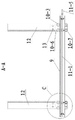
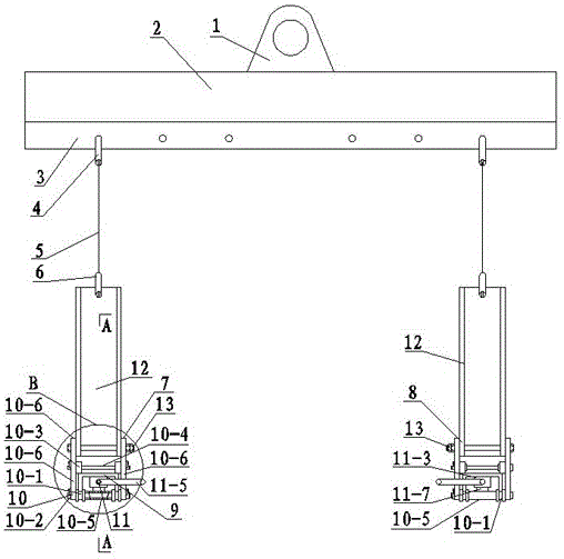
Referring to fig. 1 and 2, the present embodiment is a lifting appliance for truss floor deck plates and ALC wall panels, and mainly comprises a lifting plate 1, a lifting beam 2, a lifting hole plate 3, an upper shackle 4, a flexible connector 5, a lower shackle 6, a first lifting frame 7 and a second lifting frame 8. The hanging beam 2 is horizontally arranged and made of H-shaped steel, a web plate of the hanging beam is vertically arranged, a hanging plate 1 is welded in the middle of the top surface of an upper flange plate of the hanging beam, and a round hole is formed in the hanging plate 1 and used for being connected with a hanging hook of a hoisting machine. The middle part of the bottom surface of the lower flange plate of the hanging beam 2 is longitudinally welded with a rectangular hanging hole plate 3, the surface of the hanging hole plate 3 is vertical to the lower flange plate of the hanging beam 2, and the hanging hole plate 3 is symmetrically provided with a plurality of connecting holes. The upper shackles 4 are respectively arranged in the two symmetrical connecting holes, the upper shackles 4 are connected with the lower shackles 6 through flexible connecting pieces, the flexible connecting pieces are steel wire ropes, ring chains or hanging strips, the steel wire ropes 5 are preferably selected in the embodiment, the two lower shackles 6 are respectively arranged on the first hanging bracket 7 and the second hanging bracket 8, and the hanging beam 2 suspends the first hanging bracket 7 and the second hanging bracket 8 in a hanging manner.
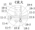
First gallows 7 and second gallows 8 symmetry set up and the structure is the same, and first gallows 7 mainly comprises floorbar 9, gyro wheel mechanism 10, guiding mechanism 11 and perpendicular roof beam 12, and the floorbar 9 level sets up, and its cross-section is the shape of falling the U, and the preferred channel-section steel of material, the notch of channel-section steel is downward. The two ends of the bottom beam 9 are symmetrically provided with roller mechanisms 10, each roller mechanism 10 mainly comprises a lower roller 10-1, a lower wheel shaft 10-2, an upper roller 10-3, an upper wheel shaft 10-4 and a shaft sleeve 10-5 side plate 10-6, the lower end surfaces of the side groove plates on the two sides of the bottom beam 8 are symmetrically provided with the lower rollers 10-1, each side is provided with two rollers, the tread surface of the lower roller 10-1 is provided with an annular groove, the lower end surface of the side groove plate is embedded into the groove, the lower rollers 10-1 are matched with the side groove plates, and the shaft holes of the two symmetrical lower rollers 10-1 are internally provided with a lower wheel shaft 10-2. A side plate 10-6 is attached to the outer side of each of the two lower rollers 10-1, two ends of a lower wheel shaft 10-2 penetrate through the side plates 10-6 respectively, the penetrating end of the lower wheel shaft 10-2 is connected with the side plate 10-6 on the side through a clamping plate, the clamping plate is clamped in a clamping groove of the lower wheel shaft 10-2, and the clamping plate is connected with the outer side face of the side plate 10-6 through a bolt. The upper idler wheels 10-3 are symmetrically arranged on two sides of the upper portion of the top plate of the bottom beam 8, each side is provided with two upper idler wheels 10-3, the upper idler wheels 10-3 are located on the inner sides of the side plates 10-6, an upper wheel shaft 10-4 is mounted in shaft holes of the two symmetrical upper idler wheels 10-3, elastic check rings are mounted on the upper wheel shaft 10-4 on the inner sides of the upper idler wheels 10-3, the upper idler wheels 10-3 are limited by the elastic check rings, two ends of the upper wheel shaft 10-4 penetrate through the two side plates 10-6 respectively, the upper wheel shaft 10-4 is connected with the side plates 10-6 through a clamping plate, the clamping plate is clamped into a clamping groove of the upper wheel shaft 10-4, and the clamping plate is connected with the outer side faces of the side plates 10-6 through bolts. The lower wheel shaft 10-2 between the two lower rollers 10-1 at the inner end of the roller mechanism 10 is sleeved with a shaft sleeve 10-5.
The roller mechanism 10 is driven by an adjusting mechanism 11, the adjusting mechanism 11 mainly comprises a lead screw 11-1, a lead screw nut 11-2, a supporting plate 11-3, a shaft seat 11-4 and a handle 11-5, the lead screw 11-1 is longitudinally arranged in a notch of the bottom beam 9, one end of the lead screw extends out of the bottom beam 9, and the extending end is provided with a rotating handle 11-5. Two ends of the screw rod 11-1 are respectively connected with the shaft seats 11-4, the shaft seats 11-4 are connected with the supporting plate 11-3 through bolts, and the supporting plate 11-3 is welded on the bottom surface of the top plate of the bottom beam 9.
The screw rod 11-1 symmetrically processes two sections of rectangular threads with opposite turning directions, two screw rod nuts 11-2 are screwed with the two sections of threads with opposite turning directions respectively, each screw rod nut 11-2 is positioned right above the shaft sleeve 10-5, a radial upper connecting plate 11-6 is welded on the peripheral surface of the screw rod nut 11-2, the plate surface of the upper connecting plate 11-6 is vertical to the axis of the screw rod nut 11-2, a radial lower connecting plate 11-7 is welded on the peripheral surface of the shaft sleeve 10-5, and the upper connecting plate 11-6 is connected with the lower connecting plate 11-7 through bolts. The handle 11-5 is rotated, the screw rod 11-1 rotates along with the handle, the two screw rod nuts 11-2 move in the same or opposite directions, the screw rod nuts 11-2 drive the shaft sleeve 10-5 to move through the upper connecting plate 11-6 and the lower connecting plate 11-7, the shaft sleeve 10-5 drives the lower wheel shaft 10-2 to move, the lower wheel 10-1 and the upper wheel 10-3 are driven to roll, and the two wheel mechanisms move in the same or opposite directions.
Each roller mechanism is provided with a vertical beam 12, the vertical beam 12 is made of channel steel, the lower end of the vertical beam 12 is arranged between the two side plates 10-6, the vertical beam 12 is connected with the two side plates 10-6 through two bolts 13, the two bolts 13 respectively penetrate through the two flange plates of the vertical beam 12, and the two bolts 13 are horizontally arranged in parallel. The upper end of the vertical beam 12 is provided with a lower shackle 6.
The hanging hole plates 3 can be two (shown in figure 5), connecting holes are symmetrically formed between the two hanging hole plates 3, pin shafts 14 penetrate through the connecting holes, and the upper shackle 4 is connected with the pin shafts 14.
When the invention is used for the first time, the hanging plate 1 at the upper part of the hanging beam 2 is hung on the hanging hook of the hoisting machinery,
and two vertical beams 12 of the first hanger 7 are connected with the hanging plate 3 at the bottom of the hanging beam 2 through two equal-length steel wire ropes 5, an upper shackle 4 and a lower shackle 6, and then the second hanger 8 is connected with the hanging plate 3 to form a whole. The adjustment is carried out according to the sizes of the plates with different specifications, the handle 11-5 is rotated, and the distance between the two vertical beams 12 of the first hanging bracket 7 and the second hanging bracket 8 is adjusted to be suitable for the width of the plates. The distance between the first hanger 7 and the second hanger 8 is adjusted by the coupling hole of the orifice plate 3.
The lifting appliance is lifted to the side of the material level by the lifting machine, the first lifting frame 7 and the second lifting frame 8 fall to the ground, the upper shackle 6 at the upper end of the outer vertical beam 12 and the bolt 13 at the lower end of the outer vertical beam are dismounted, the vertical beam 12 is horizontally placed outwards, the plates are placed on the two bottom beams 9 by the forklift, the vertical beam 12 is reset and the upper shackle 6 is installed, the vertical beam 12 is adjusted again, and the vertical beam 12 is tightly attached to the outer side face of the plates for lifting.
The invention prevents the plate from sliding during lifting, protects the plate to be intact, has no crack and corner drop, reduces the loss rate and saves the cost. After the use, one of the two bolts 13 is detached, and the vertical beam 12 is folded, so that the occupied space is reduced.
The above description is only for the purpose of illustrating the preferred embodiments of the present invention and is not to be construed as limiting the scope of the present invention, which is defined in the appended claims.