CN114803015A - Tear and remove a membrane device and demolish extranal packing production line - Google Patents
Tear and remove a membrane device and demolish extranal packing production line Download PDFInfo
- Publication number
- CN114803015A CN114803015A CN202210396873.3A CN202210396873A CN114803015A CN 114803015 A CN114803015 A CN 114803015A CN 202210396873 A CN202210396873 A CN 202210396873A CN 114803015 A CN114803015 A CN 114803015A
- Authority
- CN
- China
- Prior art keywords
- product
- top film
- film
- assembly
- positioning
- Prior art date
- Legal status (The legal status is an assumption and is not a legal conclusion. Google has not performed a legal analysis and makes no representation as to the accuracy of the status listed.)
- Pending
Links
- 238000004519 manufacturing process Methods 0.000 title claims abstract description 17
- 239000012528 membrane Substances 0.000 title claims description 6
- 238000012856 packing Methods 0.000 title description 8
- 230000007246 mechanism Effects 0.000 claims description 24
- 238000012546 transfer Methods 0.000 claims description 19
- 230000002093 peripheral effect Effects 0.000 claims description 18
- 238000005192 partition Methods 0.000 claims description 16
- 230000001174 ascending effect Effects 0.000 claims description 3
- 210000002469 basement membrane Anatomy 0.000 claims description 3
- 238000000034 method Methods 0.000 abstract description 28
- 230000008569 process Effects 0.000 abstract description 25
- 230000009286 beneficial effect Effects 0.000 abstract description 2
- 230000005540 biological transmission Effects 0.000 description 9
- 229930182555 Penicillin Natural products 0.000 description 5
- JGSARLDLIJGVTE-MBNYWOFBSA-N Penicillin G Chemical compound N([C@H]1[C@H]2SC([C@@H](N2C1=O)C(O)=O)(C)C)C(=O)CC1=CC=CC=C1 JGSARLDLIJGVTE-MBNYWOFBSA-N 0.000 description 5
- 229940049954 penicillin Drugs 0.000 description 5
- 230000033001 locomotion Effects 0.000 description 4
- 241001232787 Epiphragma Species 0.000 description 3
- 238000010586 diagram Methods 0.000 description 3
- 239000000463 material Substances 0.000 description 3
- 230000008602 contraction Effects 0.000 description 2
- 230000002349 favourable effect Effects 0.000 description 2
- 238000012986 modification Methods 0.000 description 2
- 230000004048 modification Effects 0.000 description 2
- 230000004888 barrier function Effects 0.000 description 1
- 230000008859 change Effects 0.000 description 1
- 238000013016 damping Methods 0.000 description 1
- 238000013461 design Methods 0.000 description 1
- 230000000694 effects Effects 0.000 description 1
- 230000000750 progressive effect Effects 0.000 description 1
- 230000002035 prolonged effect Effects 0.000 description 1
- 238000000926 separation method Methods 0.000 description 1
- 238000001179 sorption measurement Methods 0.000 description 1
Images





Classifications
-
- B—PERFORMING OPERATIONS; TRANSPORTING
- B65—CONVEYING; PACKING; STORING; HANDLING THIN OR FILAMENTARY MATERIAL
- B65B—MACHINES, APPARATUS OR DEVICES FOR, OR METHODS OF, PACKAGING ARTICLES OR MATERIALS; UNPACKING
- B65B69/00—Unpacking of articles or materials, not otherwise provided for
- B65B69/0033—Unpacking of articles or materials, not otherwise provided for by cutting
-
- B—PERFORMING OPERATIONS; TRANSPORTING
- B65—CONVEYING; PACKING; STORING; HANDLING THIN OR FILAMENTARY MATERIAL
- B65B—MACHINES, APPARATUS OR DEVICES FOR, OR METHODS OF, PACKAGING ARTICLES OR MATERIALS; UNPACKING
- B65B69/00—Unpacking of articles or materials, not otherwise provided for
-
- B—PERFORMING OPERATIONS; TRANSPORTING
- B65—CONVEYING; PACKING; STORING; HANDLING THIN OR FILAMENTARY MATERIAL
- B65B—MACHINES, APPARATUS OR DEVICES FOR, OR METHODS OF, PACKAGING ARTICLES OR MATERIALS; UNPACKING
- B65B69/00—Unpacking of articles or materials, not otherwise provided for
- B65B69/0025—Removing or cutting binding material, e.g. straps or bands
-
- B—PERFORMING OPERATIONS; TRANSPORTING
- B65—CONVEYING; PACKING; STORING; HANDLING THIN OR FILAMENTARY MATERIAL
- B65G—TRANSPORT OR STORAGE DEVICES, e.g. CONVEYORS FOR LOADING OR TIPPING, SHOP CONVEYOR SYSTEMS OR PNEUMATIC TUBE CONVEYORS
- B65G47/00—Article or material-handling devices associated with conveyors; Methods employing such devices
- B65G47/74—Feeding, transfer, or discharging devices of particular kinds or types
- B65G47/90—Devices for picking-up and depositing articles or materials
- B65G47/905—Control arrangements
-
- B—PERFORMING OPERATIONS; TRANSPORTING
- B65—CONVEYING; PACKING; STORING; HANDLING THIN OR FILAMENTARY MATERIAL
- B65G—TRANSPORT OR STORAGE DEVICES, e.g. CONVEYORS FOR LOADING OR TIPPING, SHOP CONVEYOR SYSTEMS OR PNEUMATIC TUBE CONVEYORS
- B65G47/00—Article or material-handling devices associated with conveyors; Methods employing such devices
- B65G47/74—Feeding, transfer, or discharging devices of particular kinds or types
- B65G47/90—Devices for picking-up and depositing articles or materials
- B65G47/907—Devices for picking-up and depositing articles or materials with at least two picking-up heads
-
- B—PERFORMING OPERATIONS; TRANSPORTING
- B65—CONVEYING; PACKING; STORING; HANDLING THIN OR FILAMENTARY MATERIAL
- B65G—TRANSPORT OR STORAGE DEVICES, e.g. CONVEYORS FOR LOADING OR TIPPING, SHOP CONVEYOR SYSTEMS OR PNEUMATIC TUBE CONVEYORS
- B65G47/00—Article or material-handling devices associated with conveyors; Methods employing such devices
- B65G47/74—Feeding, transfer, or discharging devices of particular kinds or types
- B65G47/90—Devices for picking-up and depositing articles or materials
- B65G47/91—Devices for picking-up and depositing articles or materials incorporating pneumatic, e.g. suction, grippers
- B65G47/917—Devices for picking-up and depositing articles or materials incorporating pneumatic, e.g. suction, grippers control arrangements
-
- B—PERFORMING OPERATIONS; TRANSPORTING
- B65—CONVEYING; PACKING; STORING; HANDLING THIN OR FILAMENTARY MATERIAL
- B65G—TRANSPORT OR STORAGE DEVICES, e.g. CONVEYORS FOR LOADING OR TIPPING, SHOP CONVEYOR SYSTEMS OR PNEUMATIC TUBE CONVEYORS
- B65G47/00—Article or material-handling devices associated with conveyors; Methods employing such devices
- B65G47/74—Feeding, transfer, or discharging devices of particular kinds or types
- B65G47/90—Devices for picking-up and depositing articles or materials
- B65G47/91—Devices for picking-up and depositing articles or materials incorporating pneumatic, e.g. suction, grippers
- B65G47/918—Devices for picking-up and depositing articles or materials incorporating pneumatic, e.g. suction, grippers with at least two picking-up heads
-
- B—PERFORMING OPERATIONS; TRANSPORTING
- B65—CONVEYING; PACKING; STORING; HANDLING THIN OR FILAMENTARY MATERIAL
- B65G—TRANSPORT OR STORAGE DEVICES, e.g. CONVEYORS FOR LOADING OR TIPPING, SHOP CONVEYOR SYSTEMS OR PNEUMATIC TUBE CONVEYORS
- B65G2201/00—Indexing codes relating to handling devices, e.g. conveyors, characterised by the type of product or load being conveyed or handled
- B65G2201/02—Articles
- B65G2201/0214—Articles of special size, shape or weigh
- B65G2201/022—Flat
Landscapes
- Engineering & Computer Science (AREA)
- Mechanical Engineering (AREA)
- Control And Other Processes For Unpacking Of Materials (AREA)
Abstract
The invention discloses a device for tearing off a top film and a production line for removing an outer package, wherein the device for tearing off the top film comprises: a top film acquiring member for acquiring a top film to be separated; the top film transferring assembly is connected with the top film acquiring part and used for driving the top film acquiring part to move so as to separate the top film from the product. The top film tearing device provided by the invention can separate a product from the top film, is beneficial to realizing the automatic dismantling of the outer package of the product, improves the efficiency of the outer package dismantling process, and reduces the labor intensity in the outer package dismantling process.
Description
Technical Field
The invention relates to the technical field of automatic equipment, in particular to a device for tearing off a top film, and further relates to a production line for removing an outer package.
Background
In the existing production process, when the outer package of the penicillin bottle needs to be removed, the penicillin bottle generally needs to be manually operated for standing for a long time, generally, a whole disc of penicillin bottles is about 10kg, after the outer package of the penicillin bottle is removed, the penicillin bottle needs to be manually carried to the next station, the labor intensity is high, and the removing efficiency is low.
In summary, how to reduce the labor intensity in the process of removing the outer package and improve the removal efficiency is a problem to be solved urgently by those skilled in the art.
Disclosure of Invention
In view of this, the present invention provides a device for tearing off a top film, which can be used to separate the top film from a product in an outer package of the product, thereby facilitating automation of a process of removing the outer package of the product, improving efficiency of the process of removing the outer package, and reducing labor intensity in the process of removing the outer package.
In addition, the invention also aims to provide a package removing production line comprising the top film removing device.
In order to achieve the above purpose, the invention provides the following technical scheme:
a peel-off cover device for separating a cover from a product, comprising:
a top film acquiring member for acquiring a top film to be separated;
the top film transferring assembly is connected with the top film acquiring part and used for driving the top film acquiring part to move towards the direction far away from the product so as to separate the top film from the product.
Optionally, a positioning device for positioning the product is further included, the positioning device comprising:
a side positioning assembly for limiting the position of the product perpendicular to the conveying direction;
a front and rear positioning assembly for limiting the position of the product in the conveying direction;
the pushing assembly is used for pushing the product to be positioned to be abutted against the front positioning piece and the rear positioning piece;
the side positioning assembly is arranged on at least one side of the product conveying path, and the front positioning assembly and the rear positioning assembly can move to the product conveying path.
Optionally, the side positioning assembly comprises:
the side power piece is provided with a telescopic first moving end;
the first positioning piece is connected to the first moving end and is arranged in a telescopic mode along the direction perpendicular to the conveying direction of the products.
Optionally, the fore-aft positioning assembly comprises:
the front power piece and the rear power piece are provided with telescopic second moving ends;
and the second positioning piece is connected to the second motion end and can be arranged in a lifting manner along the vertical direction.
Optionally, the top film transfer assembly comprises:
the first moving piece is provided with a first moving end capable of ascending and descending along the vertical direction, and the first moving end is connected with the top film acquiring piece;
the second moving part is provided with a movable second moving end, the moving direction of the second moving end is different from that of the first moving end, and the first moving part is connected to the second moving end so that the second moving part drives the first moving part to move.
Optionally, the top film take off is a suction cup or a clamp.
A demolition overwrap production line for removing an overwrap of a product, comprising:
the conveying device is used for bearing and conveying the products to be subjected to outer package disassembly;
the grabbing device is used for grabbing the products to be subjected to outer package removal to the conveying device;
the periphery film cutting device is provided with a cutting knife which can cut the outer package of the product along the circumferential direction so as to cut the outer package of the product into two parts, namely an upper top film and a lower bottom film;
the tearing top film device is any one of the tearing top film devices; the tearing top film device is used for separating the upper top film of the product cut by the peripheral film cutting device from the product;
a bottom film removing means for removing a lower bottom film of the product from which the upper top film is removed;
grabbing device the periphery is cut the membrane device tear and is removed the top membrane device basement membrane remove device and follow conveyer's direction of delivery sets gradually.
Optionally, the peripheral cutting means comprises:
a fixed seat;
the mounting rack comprises a first mounting rack and a second mounting rack, at least one of the first mounting rack and the second mounting rack is movably arranged on the fixed seat so as to adjust the distance between the first mounting rack and the second mounting rack;
the cutting knife, including install in the first cutting knife of first mounting bracket with install in the second cutting knife of second mounting bracket, just first cutting knife with the relative and interval setting of second cutting knife.
The adjusting assembly is connected with at least one of the first cutting knife and the second cutting knife and is used for adjusting the distance between the first cutting knife and the second cutting knife which are oppositely arranged;
the adjustment assembly is mounted to the first mounting bracket or the second mounting bracket.
Optionally, the first cutting knife is rotatably mounted on the first mounting frame, and the second cutting knife is rotatably mounted on the second mounting frame.
Optionally, the conveying device includes a reversing segment and at least two transmission segments with different transmission directions, and the reversing segment is used to connect adjacent transmission segments with different transmission directions.
Optionally, the conveying device is an L-shaped structure, and the reversing section is located at an included angle of the L-shaped structure.
Optionally, the gripping device includes a mechanical arm and a clamping jaw disposed at a distal end of the mechanical arm.
Optionally, the gripping device further comprises a safety grating arranged outside the gripping device.
Optionally, the device for tearing off the top film comprises a sucker for sucking the top film and a transferring module connected to the sucker, wherein the transferring module has vertical and horizontal degrees of freedom.
Optionally, the separator gripping device is disposed at a conveying start end of the conveying device, and includes:
the suction assembly is used for sucking the partition plate to be transferred;
the partition plate removing module is used for driving the suction assembly to lift and move along the direction vertical to the lifting direction.
Optionally, the device further comprises a shooting device arranged at the starting end of the conveying device, wherein the shooting device is arranged towards the product to be subjected to outer package removal and is used for shooting the outer package of the product.
Optionally, the carrier film removing device comprises:
a frame;
the product jacking mechanism is movably arranged on the frame and used for clamping the product by the side edge and lifting the product;
and the bottom film grabbing component is movably arranged on the frame and is used for grabbing the bottom film and separating the bottom film from the product.
In the process of using the device for tearing off the top film, the top film transfer component is controlled to drive the top film obtaining part to move to the position where the top film can be obtained, then the top film obtaining part is controlled to obtain the top film, and then the top film transfer component is controlled to drive the top film obtaining part to move in the direction far away from the product, so that the product is separated from the top film.
Compared with the prior art, the top film tearing device provided by the invention can separate a product from a top film, is beneficial to realizing automatic dismantling of an outer package of the product, improves the efficiency of the outer package dismantling process, and reduces the labor intensity in the outer package dismantling process.
In addition, the invention also provides an outer package removing production line comprising the top film removing device.
Drawings
In order to more clearly illustrate the embodiments of the present invention or the technical solutions in the prior art, the drawings used in the description of the embodiments or the prior art will be briefly described below, it is obvious that the drawings in the following description are only embodiments of the present invention, and for those skilled in the art, other drawings can be obtained according to the provided drawings without creative efforts.
FIG. 1 is a schematic design diagram of an embodiment of a removal line for removing overpacks according to the present invention;
FIG. 2 is a schematic structural view of a transfer device;
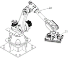
FIG. 3 is a schematic structural view of the grasping apparatus;
FIG. 4 is a schematic structural diagram of a peripheral film cutting device;
FIG. 5 is a schematic view of another angle of the peripheral film cutting device;
FIG. 6 is a schematic view of a first angled configuration of the peel away cover device;
FIG. 7 is a second angled configuration of the peel away cover device;
FIG. 8 is a third angle schematic view of the peel away cover device;
FIG. 9 is a schematic view showing the structure of a carrier film removing apparatus;
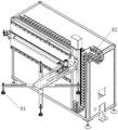
FIG. 10 is a schematic view of a separator gripping device;
fig. 11 is a schematic structural diagram of the photographing apparatus.
In fig. 1-11:
1 is a conveying device, 11 is a first conveying section, 12 is a second conveying section, 13 is a reversing section, 2 is a gripping device, 21 is a clamping jaw, 22 is a mechanical arm, 3 is a peripheral film cutting device, 31 is a cutting knife, 32 is a mounting frame, 321 is a first mounting frame, 322 is a second mounting frame, 323 is a clamping part, 324 is a first sliding rail, 325 is a second sliding rail, 326 is a bottom plate, 33 is an adjusting component, 34 is a power structure, 35 is a base, 36 is a fixing seat, 37 is a cutting knife adjuster, 4 is a top film tearing device, 41 is a top film obtaining component, 42 is a top film transferring component, 421 is a first moving component, 422 is a second moving component, 43 is a side positioning component, 431 is a side power component, 432 is a first positioning component, 44 is a front and rear positioning component, 441 is a front and rear power component, 442 is a second positioning component, 45 is a material pushing component, 5 is a bottom film removing device, 51 is a frame, 52 is a product lifting mechanism, 53 is a bottom film grabbing component, 6 is a shooting device, 7 is a safety grating, 8 is a clapboard grabbing device, 81 is a suction component, and 82 is a clapboard removing module.
Detailed Description
The technical solutions in the embodiments of the present invention will be clearly and completely described below with reference to the drawings in the embodiments of the present invention, and it is obvious that the described embodiments are only a part of the embodiments of the present invention, and not all of the embodiments. All other embodiments, which can be derived by a person skilled in the art from the embodiments given herein without making any creative effort, shall fall within the protection scope of the present invention.
The core of the invention is to provide a production line for removing the outer package, which can realize the automatic removal of the outer package of the product, improve the efficiency of the outer package removing process and reduce the labor intensity in the outer package removing process.
Please refer to fig. 1-11.
As shown in fig. 6, the present embodiment discloses a device 4 for removing a top film, which is used for separating the top film from a product, and comprises:
a top film acquiring member 41 for acquiring a top film to be separated;
the top film transferring component 42 is connected with the top film acquiring component 41, and the top film transferring component 42 is used for driving the top film acquiring component 41 to move towards the direction far away from the product so as to separate the top film from the product.
The top film acquiring member 41 may be a suction cup or a clamp for sucking or gripping the top film, as determined in accordance with the actual situation.
In the process of using the top film tearing device 4 provided in the present embodiment, the top film transfer component 42 may be controlled to drive the top film obtaining component 41 to move to a position where the top film can be obtained, and the top film transfer component 42 may be a mobile module, or a mobile robot, etc.; then, controlling the top film obtaining part 41 to obtain the top film, wherein the top film obtaining part 41 can be a sucker for obtaining the top film in an adsorption mode, or setting the top film obtaining part 41 as a clamping jaw for obtaining the top film in a clamping mode, and the method is determined according to actual conditions; and then the top film transfer assembly 42 is controlled to drive the top film acquiring part 41 to move towards the direction far away from the product, so that the product is separated from the top film.
Compare in prior art, the tear and remove epiphragma device 4 that this embodiment provided can be with product and epiphragma separation, is favorable to realizing that the automation of product extranal packing is demolishd, improves the extranal packing and demolishs the efficiency of process, reduces the artifical intensity of tearing open extranal packing in-process.
In a particular embodiment, as shown in fig. 7 and 8, the tear-off top film device 4 further comprises a positioning device for positioning the product, the positioning device comprising:
a side positioning assembly 43 for limiting the position of the product perpendicular to the conveying direction;
a front-to-back positioning assembly 44 for limiting the position of the products in the conveying direction;
the material pushing assembly 45 is used for pushing a product to be positioned to be abutted against the front positioning piece and the rear positioning piece;
the side positioning members 43 are disposed at least at one side of the product conveying path, and the front and rear positioning members 44 are movable to the product conveying path.
In the using process, products with outer packages are conveyed according to a preset conveying path, when a top film of the outer packages is cut, the products are conveyed to a top film tearing position, when the products are conveyed to the preset top film tearing position, at least one side of the product conveying path is provided with a side positioning assembly 43, the side positioning assembly 43 is used for limiting the position of the products perpendicular to the conveying direction, a front positioning assembly 44 and a rear positioning assembly 44 move to the conveying path of the products, a material pushing assembly 45 is used for pushing the products to be positioned to abut against the front positioning assembly 44 and the rear positioning assembly 44 so as to limit the positions of the products along the conveying direction, and the products are positioned, so that the top film is positioned at the position which can be obtained by a top film obtaining piece 41, and then the top film transferring assembly 42 is controlled to drive the top film obtaining piece 41 to move and obtain the top film; it should be noted that the movement of the top film transfer assembly 42 may be controlled by a general control device of the top film tearing device, or the movement of the top film transfer assembly 42 may be controlled by a controller of the top film transfer assembly 42 itself, which is specifically determined according to actual conditions.
The setting of positioning device in this embodiment has improved the precision that obtains of epiphragma, can effectively improve and tear off efficiency.
As shown in fig. 7, the side positioning assembly includes:
a side power member 431 provided with a retractable first moving end;
the first positioning member 432 is connected to the first moving end, and the first positioning member 432 is movably disposed in a direction perpendicular to the conveying direction of the product.
Specifically, the first positioning member 432 may be a plate-shaped structure, and in the process of conveying the product, the first positioning member 432 is driven by the side power member 431 to move to contact with the outer package or the outer side surface of the product.
As shown in fig. 8, the front-rear positioning assembly 44 includes:
the front and rear power pieces 441 are provided with telescopic second moving ends;
the second positioning element 442 is connected to the second moving end, and the second positioning element 442 is disposed in a lifting manner along the vertical direction.
Specifically, the second positioning element 442 may be a plate-shaped structure, and in the process of conveying the product, the second positioning element 442 is driven by the front and rear power elements to descend to the conveying path of the product, and the pushing assembly 45 is controlled to push the product to be positioned to abut against the second positioning element 442; it should be noted that the pushing assembly 45 may be controlled to operate by a master control device of the film tearing and ejecting device, or the pushing assembly 45 may be controlled to operate by a controller of the pushing assembly 45, which is specifically determined according to actual conditions.
The pushing assembly 45 may be a pushing plate, a pushing rod, or the like movable along a conveying path of the product, and may be driven by a power device of an air cylinder, a motor, or an electric cylinder, and is specifically determined according to actual conditions.
In one embodiment, as shown in fig. 6, the top film transfer assembly 42 includes:
a first moving member 421 having a first moving end capable of ascending and descending in the vertical direction, the first moving end being connected to the top film taking member 41;
the second moving member 422 has a movable second moving end, the moving direction of the second moving end is different from the moving direction of the first moving end, and the first moving member 421 is connected to the second moving end, so that the second moving member 422 drives the first moving member 421 to move.
Specifically, the second moving end may be moved along the horizontal direction, or other directions meeting the requirements, which is determined specifically according to the actual situation and is not described herein again.
It should be noted that the first moving member 421, the second moving member 422, the lateral power member 431, and the front and rear power members 441 may be power members such as cylinders, motors, and electric cylinders, which are determined according to actual situations and are not described herein. As shown in fig. 6, the second moving member 422 is a rodless cylinder, a moving end of the second moving member 422 is connected to the first moving member 421 and drives the first moving member 421 to move along the setting direction of the second moving member 422, and a tow chain is connected between the second moving member 422 and the first moving member 421, so that a line and a pipeline can be conveniently set; the telescopic end of the second moving member 421 is connected to the top film capturing member 41 to drive the top film capturing member 41 to lift.
This embodiment discloses a demolish extranal packing production line for get rid of the extranal packing of product, include:
the conveying device 1 is used for bearing and conveying products to be subjected to outer package disassembly;
the gripping device 2 is used for gripping the products to be subjected to outer package removal to the conveying device 1;
the periphery film cutting device 3 is provided with a cutting knife 31 which can cut the outer package of the product along the circumferential direction so as to cut the outer package of the product into two parts of an upper top film and a lower bottom film;
the top film tearing device 4, wherein the top film tearing device 4 is the top film tearing device 4; the top film tearing device 4 is used for separating the top film on the upper part of the product cut by the peripheral film cutting device 3 from the product;
a bottom film removing means 5 for removing a lower bottom film of the product from which the upper top film is removed;
the gripping device 2, the peripheral film cutting device 3, the top film tearing device 4 and the bottom film removing device 5 are sequentially arranged along the conveying direction of the conveying device 1.
It should be noted that the conveying device 1 mentioned in this embodiment may be a conveying line formed by combining a plurality of rollers, a conveying line formed by a driving wheel and a conveying belt, or other conveying equipment, which is determined according to actual situations and is not described herein again.
In the process of removing the outer package production line provided by the specific embodiment, the product to be removed from the outer package is grabbed to the conveying device 1 by the grabbing device 2, the product is conveyed to the periphery film cutting device 3 by the conveying device 1, the outer package is cut into the upper top film and the lower bottom film by the periphery film cutting device 3 along the circumferential direction of the product to be removed from the outer package, the product is conveyed to the top film removing device 4 by the conveying device 1, the upper top film is grabbed and moved to the upper top film collecting position by the top film removing device 4, the product is conveyed to the bottom film removing device 5 by the conveying device 1, the lower bottom film is removed by the bottom film removing device 5, the product is conveyed to the next station by the conveying device 1, and the outer package removal of the product is completed.
Compared with the prior art, the external package dismantling production line provided by the specific embodiment can realize automatic dismantling of external packages of products, improves the efficiency of the external package dismantling process, and reduces the labor intensity in the external package dismantling process.
In a particular embodiment, the peripheral film cutting device 3 comprises:
a fixed base 36;
the mounting bracket 32 comprises a first mounting bracket 321 and a second mounting bracket 322, at least one of the first mounting bracket 321 and the second mounting bracket 322 is movably arranged on the fixed base 326 to adjust the distance between the first mounting bracket 321 and the second mounting bracket 322;
the cutter 31 includes a first cutter 311 mounted on the first mounting rack 321 and a second cutter 312 mounted on the second mounting rack 322, and the first cutter 311 and the second cutter 312 are disposed opposite to each other and spaced apart from each other.
An adjusting assembly 33 connected to at least one of the first cutter 311 and the second cutter 312 for adjusting a distance between the first cutter 311 and the second cutter 312 which are oppositely disposed;
the adjustment assembly 33 is mounted to the first mount 321 or the second mount 322.
Preferably, the first cutting knife 311 can be rotatably mounted on the first mounting frame 321, the second cutting knife 312 can be rotatably mounted on the second mounting frame 322, and in the process of cutting the outer package of the product, after the first cutting knife 311 or the second cutting knife 312 touches the product in the outer package, the rotation can be performed, so that the product is prevented from being scratched, and the product is prevented from being damaged.
In one embodiment, the first mounting frame 321 is movably disposed relative to the fixing base 36, and the first mounting frame 321 is provided with a clamping portion 323 capable of moving to abut against the product, the clamping portion 323 is used for positioning the product, and the first cutting blade 41 can extend out of the edge of the clamping portion 323.
It should be noted that the clamping portion 323 may be provided only on the first mounting frame 31, the clamping portion 323 may be provided only on the second mounting frame 32, or the clamping portions 323 may be provided on both the first mounting frame 31 and the second mounting frame 32, which is determined according to the actual situation.
The fixed seat 36 is provided with an adjusting assembly 33 and a first slide rail 324, at least one of the first mounting frame 321 and the second mounting frame 322 is slidably mounted on the first slide rail 324, and an extending end of the adjusting assembly 33 is connected with at least one of the first mounting frame 321 and the second mounting frame 322, so that the first mounting frame 31 and the second mounting frame 32 are relatively close to or far away from each other, and thus the distance between the first cutting knife 311 and the second cutting knife 312 which are relatively arranged is adjusted.
As shown in fig. 5, the fixing base 36 is provided with two mounting brackets 32, including a first mounting bracket 321 and a second mounting bracket 322, wherein the second mounting bracket 322 is fixedly disposed on the fixing base 36, the first mounting bracket 321 is slidably mounted on the fixing base 36 along a first sliding rail 324, the first sliding rail 324 is disposed on a bottom plate 326, and the bottom plate 326 is connected to the fixing base 36; the first mounting frame 321 can slide along the first slide rail 324 by adjusting the extension and contraction of the adjusting assembly 33, so that the first cutting knife 311 and the second cutting knife 312 are relatively close to or far away from each other, the distance between the first cutting knife 311 and the second cutting knife 312 which are oppositely arranged is adjusted, and meanwhile, the distance between the clamping part 323 and the second mounting frame 322 can be adjusted by adjusting the relative distance between the first mounting frame 321 and the second mounting frame 322; in fig. 4 and 5, the clamping portion 323 is an elongated plate-shaped structure, and the adjustment assembly 33 is extended to press the clamping portion 323 against the side surface of the outer package of the product, so as to position the product, and the first cutter 311 and the second cutter 312 are extended into the outer package of the product to a desired length.
In a specific embodiment, the first cutting knife 311 is rotatably disposed on the first mounting frame 321, the second cutting knife 312 is rotatably disposed on the second mounting frame 322, the first cutting knife 311 and the second cutting knife 312 are both mounted on the mounting frame 32 through a rotating shaft, and the cutting device further includes a spring mechanism mounted on the rotating shaft, the spring mechanism includes a first spring mechanism and a second spring mechanism, the first spring mechanism provides resistance for the rotation of the first cutting knife 311, and the second spring mechanism provides resistance for the rotation of the second cutting knife 312.
It should be noted that the spring mechanism may be a damping spring, so that the cutting knife 31 can keep the angle fixed without external force, and when the cutting knife touches a hard product, the cutting knife can overcome the resistance provided by the spring mechanism to rotate, thereby preventing the cutting knife 31 from damaging the product or damaging the cutting knife 31.
The cutting device in this embodiment has a certain protection effect on the cutter 31 and the product in the using process, and the service life of the cutting device can be prolonged.
In a specific embodiment, the fixed seat 36 is arranged on the base 35 in a liftable manner, the base 35 is a U-shaped structure with an upward opening, the power structure 34 is mounted at the bottom of the base 35, the power structure 34 can be a lifting cylinder, the base 35 is provided with a second slide rail 325 in the vertical direction, the fixed seat 36 is slidably arranged along the second slide rail 325, and the extending end of the power structure 34 is connected with the fixed seat 36; the height of the cutting knife 31 can be adjusted by controlling the extension and contraction of the power structure 34.
As shown in fig. 1 and 4, the whole of the mounting frame 32 of the peripheral film cutting device 3 mounted on the conveying device 1 can be driven by the power structure 34 at the lower part in fig. 4 to lift and lower so as to adjust the cutting height, and the adjusting assembly 33 can push the first mounting frame 321 to move relative to the second mounting frame 322 so as to adjust the distance between the two oppositely arranged cutting knives 31, so as to adapt to products with different sizes; meanwhile, one end of the first mounting bracket 321 facing the product is provided with a clamping part 323 for clamping and positioning the product; for example, as shown in fig. 1, two peripheral film cutting devices 3 are provided, the outer package of the product is a rectangular parallelepiped, and the two peripheral film cutting devices 3 respectively cut the outer package of the product in the length direction and the width direction, thereby completing the peripheral cutting, and cutting the outer package of the product into two parts, i.e., an upper top film and a lower bottom film. The adjustment assembly 33 may be a pneumatic cylinder or other powered structure.
When the outer package of the product is in other shapes, the number of the outer peripheral film cutting devices 3 can be increased according to actual conditions, and the orientation of the cutting knife 31 is set, which is determined according to actual conditions and is not described herein.
In a specific embodiment, the conveying device 1 comprises a reversing segment 13 and at least two conveying segments with different conveying directions, wherein the reversing segment 13 is used for connecting adjacent conveying segments with different conveying directions.
As shown in fig. 1, the conveying device 1 is an L-shaped structure, the reversing section 13 is located at an included angle of the L-shaped structure, and the two gripping devices are used for gripping the products to be subjected to outer package removal to the conveying device 1; as shown in fig. 2, the conveying device 1 includes a first conveying section 11, a second conveying section 12 and a reversing section 13 connecting the first conveying section 11 and the second conveying section 12, after the products pass through the reversing section 13, the products do not rotate, for example, when the product packages are cuboids, the long side of the cuboid of the first conveying section 11 is along the conveying direction, and the short side of the cuboid is along the conveying direction of the second conveying section 12, so that the cutting knives 31 of the peripheral film cutting device 3 are arranged at two sides perpendicular to the conveying direction of the conveying device 1, grooves for fixing the products can be arranged on the conveying device 1 to limit the positions of the products on the conveying device 1 and adjust the distance between the cutting knives 31 and the products, or a shooting device 6 is added for detecting the distance between the cutting knives 31 and the products; ensures that the outer package of the product can be torn by the cutter 31 when passing through the outer peripheral film cutting device 3.
In this embodiment, set up conveyer 1 into including the different transmission section of two sections at least transmission direction, can realize the change of product transmission direction in transportation process, be favorable to realizing the rational utilization in space, make things convenient for periphery to cut membrane device 3 and cut the outer packing.
In one embodiment, the gripping device 2 includes a robot 22 and a gripper 21 disposed at a distal end of the robot 22; as shown in fig. 3, the robot arm 22 has multiple axes of freedom, and as shown in fig. 1, the robot arm 22 can move the gripper 21 and the product is gripped by the transfer device 1 from the stacking position.
Preferably, a safety light barrier 7 is further included, which is arranged outside the gripping device 2.
In a specific embodiment, the products are stacked before the outer package is removed, and a partition plate is arranged between two adjacent layers of products, so that the partition plate between the adjacent products needs to be removed when the products are loaded; specifically, a partition plate gripping device 8 may be provided, the partition plate gripping device 8 being provided at the conveying start end of the conveying device 1, the partition plate gripping device 8 including: the sucking component 81 is used for sucking the partition plate to be transferred; the partition removing module 82 is provided with a suction component 81 mounted on the partition removing module 82, and the partition removing module 82 is used for driving the suction component 81 to lift and move.
As shown in fig. 10, the sucking assembly 81 may be a suction cup or other structures meeting the requirement, the suction cup in the sucking assembly 81 in fig. 10 is disposed in a cross shape, and is driven by the separator removing module 82 to lift and move for removing the separator between the products, so as to facilitate the grabbing device 2 to grab the products with the outer package. The partition removing module 82 may include a vertical moving mechanism and a lateral moving mechanism, a moving end of one of the vertical moving mechanism and the lateral moving mechanism is connected to the other, as shown in fig. 10, the lateral moving mechanism is a lateral cylinder, a moving end of the lateral cylinder is connected to the vertical moving mechanism, the vertical moving mechanism is a rodless cylinder or a one-way module, and the suction assembly 81 is disposed at a moving end of the vertical moving mechanism.
In a specific embodiment, the device further comprises a shooting device 6 arranged at the starting end of the conveying device 1, wherein the shooting device 6 is arranged towards the product to be subjected to outer package removal and is used for shooting the outer package of the product, and in the actual working process, the model and the type of the product can be judged according to the image of the outer package of the product shot by the shooting device 6, so that the conveying device 1, the grabbing device 2, the peripheral film cutting device 3, the top film tearing device 4, the bottom film removing device 5 and the like can be adjusted to a proper motion program.
As shown in fig. 9, the bottom film removing device 5 is provided with a frame 51, a product jacking mechanism 52 and a bottom film grabbing assembly 53, wherein the product jacking mechanism 52 and the bottom film grabbing assembly 53 are both installed on the frame 51, and of course, the bottom film removing device 5 may also be in other structural forms meeting the requirements, which is specifically determined according to actual situations. In the using process, when the product moves to the position corresponding to the product jacking mechanism 52, the product jacking mechanism 52 upwards supports the product, and in the process of upwards supporting the product, the product jacking mechanism 52 clamps the product by the side edge of the product to avoid clamping the bottom film; after the product is supported, the bottom film grabbing component 53 moves to a position for grabbing the bottom film, grabs the bottom film and drives the bottom film to move in a direction away from the product so as to separate the bottom film from the product; as shown in fig. 9, the film grabbing assembly 53 may move the base film downward and rightward (the side away from the product), thereby separating the base film from the product.
The references to "first" and "second" in the first transmission section 11, the second transmission section 12, the first mounting rack 321 and the second mounting rack 322 are only used to distinguish the difference in position, and are not in sequence.
The embodiments in the present description are described in a progressive manner, each embodiment focuses on differences from other embodiments, and the same and similar parts among the embodiments are referred to each other. Any combination of all embodiments provided by the present invention is within the scope of the present invention, and will not be described herein.
The device for tearing off the top film and the production line for removing the outer package provided by the invention are described in detail above. The principles and embodiments of the present invention are explained herein using specific examples, which are presented only to assist in understanding the method and its core concepts. It should be noted that, for those skilled in the art, it is possible to make various improvements and modifications to the present invention without departing from the principle of the present invention, and those improvements and modifications also fall within the scope of the claims of the present invention.
Claims (16)
1. A device for removing a cover sheet for separating the cover sheet from a product, comprising:
a top film acquiring member (41) for acquiring a top film to be separated;
the top film transferring component (42), the top film acquiring part (41) is connected to the top film transferring component (42), and the top film transferring component (42) is used for driving the top film acquiring part (41) to move towards the direction far away from the product so as to separate the top film from the product.
2. The tear-off top film device according to claim 1, further comprising a positioning apparatus for positioning the product, the positioning apparatus comprising:
a lateral positioning assembly (43) for limiting the position of the products perpendicular to the conveying direction;
a front-to-back positioning assembly (44) for limiting the position of the products in the conveying direction;
the pushing assembly (45) is used for pushing the product to be positioned to be abutted against the front positioning piece and the rear positioning piece;
the side positioning assembly (43) is disposed at least one side of the product conveying path, and the front and rear positioning assembly (44) is movable to the product conveying path.
3. The tear-off top film device according to claim 2, wherein the side edge positioning assembly (43) comprises:
the side power piece (431) is provided with a telescopic first moving end;
the first positioning piece (432) is connected to the first moving end, and the first positioning piece (432) can be movably arranged along the direction perpendicular to the conveying direction of the products.
4. The tear-off top film device according to claim 2, wherein said front-to-back positioning assembly (44) comprises:
a front and rear power member (441) provided with a retractable second moving end;
and the second positioning part (442) is connected to the second moving end, and the second positioning part (442) can be arranged in a lifting manner along the vertical direction.
5. The tear-off top film device according to any one of claims 1 to 4, wherein the top film transfer assembly (42) comprises:
a first moving member (421) having a first moving end capable of ascending and descending along a vertical direction, wherein the first moving end is connected with the top film acquiring member (41);
the second moving part (422) is provided with a movable second moving end, the moving direction of the second moving end is different from that of the first moving end, and the first moving part (421) is connected to the second moving end so that the second moving part (422) drives the first moving part (421) to move.
6. The tear-off cover device according to any one of claims 1 to 5, wherein said cover obtaining member (41) is a suction cup or a clamp.
7. A demolition overwrap production line for removing overwrap from a product, comprising:
a conveying device (1) for carrying and conveying the products to be unpacked;
gripping means (2) for gripping the products to be overwrapped to the transfer device (1);
the periphery film cutting device (3) is provided with a cutting knife (31) capable of cutting the outer package of the product along the circumferential direction so as to cut the outer package of the product into an upper top film and a lower bottom film;
-a tear-off top film device (4), said tear-off top film device (4) being a tear-off top film device (4) according to any one of claims 1 to 6; the tearing top film device (4) is used for separating the upper top film of the product cut by the peripheral film cutting device (3) from the product;
bottom film removing means (5) for removing a lower bottom film of the product from which the upper top film is removed;
grabbing device (2), periphery film cutting device (3), tear and remove top membrane device (4), basement membrane remove device (5) are followed the direction of delivery of conveyer (1) sets gradually.
8. The overwrap removal line according to claim 7, characterized in that said peripheral film cutting means (3) comprise:
a fixed seat (36);
a mounting rack (32) comprising a first mounting rack (321) and a second mounting rack (322), wherein at least one of the first mounting rack (321) and the second mounting rack (322) is movably arranged on the fixed seat (326) to adjust the distance between the first mounting rack (321) and the second mounting rack (322);
the cutting knife (31) comprises a first cutting knife (311) arranged on the first mounting frame (321) and a second cutting knife (312) arranged on the second mounting frame (322), and the first cutting knife (311) and the second cutting knife (312) are arranged oppositely and at intervals;
an adjustment assembly (33) connected to at least one of the first cutter (311) and the second cutter (312) for adjusting a distance between the first cutter (311) and the second cutter (312) in an opposed arrangement;
the adjustment assembly (33) is mounted to the first mounting bracket (321) or the second mounting bracket (322).
9. The overpack removal production line of claim 8, wherein the first cutter (311) is rotatably mounted to the first mounting bracket (321), and the second cutter (312) is rotatably mounted to the second mounting bracket (322).
10. The takedown overwrap production line according to claim 7, characterized in that said transfer device (1) comprises a diverting section (13) and at least two transfer sections with different transfer directions, said diverting section (13) being intended to connect adjacent transfer sections with different transfer directions.
11. The demolition overwrap line according to claim 10, characterized in that the conveyor (1) is an L-shaped structure, the turnaround section (13) being located at a corner of the L-shaped structure.
12. The overwrap removal line according to claim 7, characterized in that said gripping means (2) comprise a robot arm (22) and a gripping jaw (21) arranged at the end of said robot arm (22).
13. The overwrap removal line according to claim 12, further comprising a safety grating (7) arranged outside said gripping means (2).
14. The overwrap removal production line according to any one of claims 7 to 13, further comprising a separator gripping device (8), said separator gripping device (8) being disposed at a delivery start end of said conveyor (1), said separator gripping device (8) comprising:
the suction assembly (81) is used for sucking the partition plate to be transferred;
the partition plate removing module (82) is provided with the sucking assembly (81), the sucking assembly is installed on the partition plate removing module (82), and the partition plate removing module (82) is used for driving the sucking assembly (81) to lift and move along the direction perpendicular to the lifting direction.
15. The demolition overwrap line according to any one of claims 7 to 13, further comprising a shooting device (6) arranged at the starting end of said conveyor (1), said shooting device (6) being arranged towards said products to be overwrapped and being adapted to shoot the overwrappings of said products.
16. The overwrap removal line according to any one of claims 7 to 13, wherein the basement membrane removal means (5) comprise:
a frame (51);
a product lifting mechanism (52) movably arranged on the frame (51) and used for clamping the product by the side edge and lifting the product;
and the bottom film grabbing component (53) is movably arranged on the frame (51) and is used for grabbing the bottom film and separating the bottom film from the product.
Priority Applications (1)
| Application Number | Priority Date | Filing Date | Title |
|---|---|---|---|
| CN202210396873.3A CN114803015A (en) | 2022-04-15 | 2022-04-15 | Tear and remove a membrane device and demolish extranal packing production line |
Applications Claiming Priority (1)
| Application Number | Priority Date | Filing Date | Title |
|---|---|---|---|
| CN202210396873.3A CN114803015A (en) | 2022-04-15 | 2022-04-15 | Tear and remove a membrane device and demolish extranal packing production line |
Publications (1)
| Publication Number | Publication Date |
|---|---|
| CN114803015A true CN114803015A (en) | 2022-07-29 |
Family
ID=82537395
Family Applications (1)
| Application Number | Title | Priority Date | Filing Date |
|---|---|---|---|
| CN202210396873.3A Pending CN114803015A (en) | 2022-04-15 | 2022-04-15 | Tear and remove a membrane device and demolish extranal packing production line |
Country Status (1)
| Country | Link |
|---|---|
| CN (1) | CN114803015A (en) |
Cited By (2)
| Publication number | Priority date | Publication date | Assignee | Title |
|---|---|---|---|---|
| CN117602189A (en) * | 2023-11-23 | 2024-02-27 | 广州三拓识别技术有限公司 | Full-automatic film detaching equipment |
| CN117776075A (en) * | 2024-02-26 | 2024-03-29 | 江苏新美源机械有限公司 | Beverage filling mechanism |
-
2022
- 2022-04-15 CN CN202210396873.3A patent/CN114803015A/en active Pending
Cited By (3)
| Publication number | Priority date | Publication date | Assignee | Title |
|---|---|---|---|---|
| CN117602189A (en) * | 2023-11-23 | 2024-02-27 | 广州三拓识别技术有限公司 | Full-automatic film detaching equipment |
| CN117776075A (en) * | 2024-02-26 | 2024-03-29 | 江苏新美源机械有限公司 | Beverage filling mechanism |
| CN117776075B (en) * | 2024-02-26 | 2024-05-03 | 江苏新美源机械有限公司 | Beverage filling mechanism |
Similar Documents
| Publication | Publication Date | Title |
|---|---|---|
| CN205312656U (en) | Bottle palletizing machine | |
| CN109719188B (en) | A punching and swinging device | |
| CN106829500B (en) | Servo oil-applying sheet material rotary positioning machine | |
| CN217321073U (en) | Tear and remove a membrane device and demolish extranal packing production line | |
| CN109969467B (en) | Book page collecting equipment | |
| CN108946155B (en) | Automatic cover plate and cover welding device for storage battery | |
| CN113997310A (en) | Material suction device and suction method for logistics stacking robot | |
| CN110027899B (en) | Production line, feeding device and connection mechanism | |
| CN220420634U (en) | Battery production line | |
| CN209905250U (en) | High-speed arrangement machine | |
| CN109051118B (en) | Automatic lidding device for batteries | |
| CN113277325B (en) | Automatic stacking system | |
| CN210942419U (en) | Ceramic tile packing machine | |
| CN111731785A (en) | Automatic unstacking and smelting production system for blocky paraffin | |
| CN211056218U (en) | Automatic waste discharge stacking equipment | |
| CN114955080B (en) | Fully automatic paper stack detection production equipment set | |
| CN217836373U (en) | Baffle transfer device and demolish extranal packing production line | |
| CN114988128A (en) | Full-automatic high-speed unstacker | |
| CN212863191U (en) | Automatic stacker crane | |
| CN211733165U (en) | Automatic stacking production line | |
| CN110386466B (en) | Wine bottle unstacking device | |
| CN210881102U (en) | Automatic bottom box feeding machine | |
| CN113071143A (en) | Carton die cutting circular die device and process thereof | |
| CN220244821U (en) | Panel pile up neatly device | |
| CN114620301A (en) | Baffle transfer device and demolish extranal packing production line |
Legal Events
| Date | Code | Title | Description |
|---|---|---|---|
| PB01 | Publication | ||
| PB01 | Publication | ||
| SE01 | Entry into force of request for substantive examination | ||
| SE01 | Entry into force of request for substantive examination |